Recently I purchased a few “Smart” LEDs from a site called LimitlessLED due to positive feedback from a close friend. After all was said and done, I walked away with 3 RGB LED Bulbs, a remote control, and one of their cool WiFi Receiver Bridges. After waiting a few weeks everything showed up and was working fine out of the box, except the WiFi Bridge. Thus started my journey to figure out what in the hell was going on which ended with me converting the adapter to work from a Raspberry Pi.
So after receiving my stuff, I set off to setup the little WiFi receiver. When I first got it, I took it out and set it up with its companion android application which worked great, but once it was paired to my home network the problems started coming. The problem is I live in a somewhat high density area, so there are TON’s of wireless networks in my area, and for some reason this little receiver bridge loves to drop, ignore, or just plain not forward any packets sent to it over my network. I tried different areas, rooms, hell even WiFi channels, but no matter what I did it was impossible to get a consistent link to the unit.
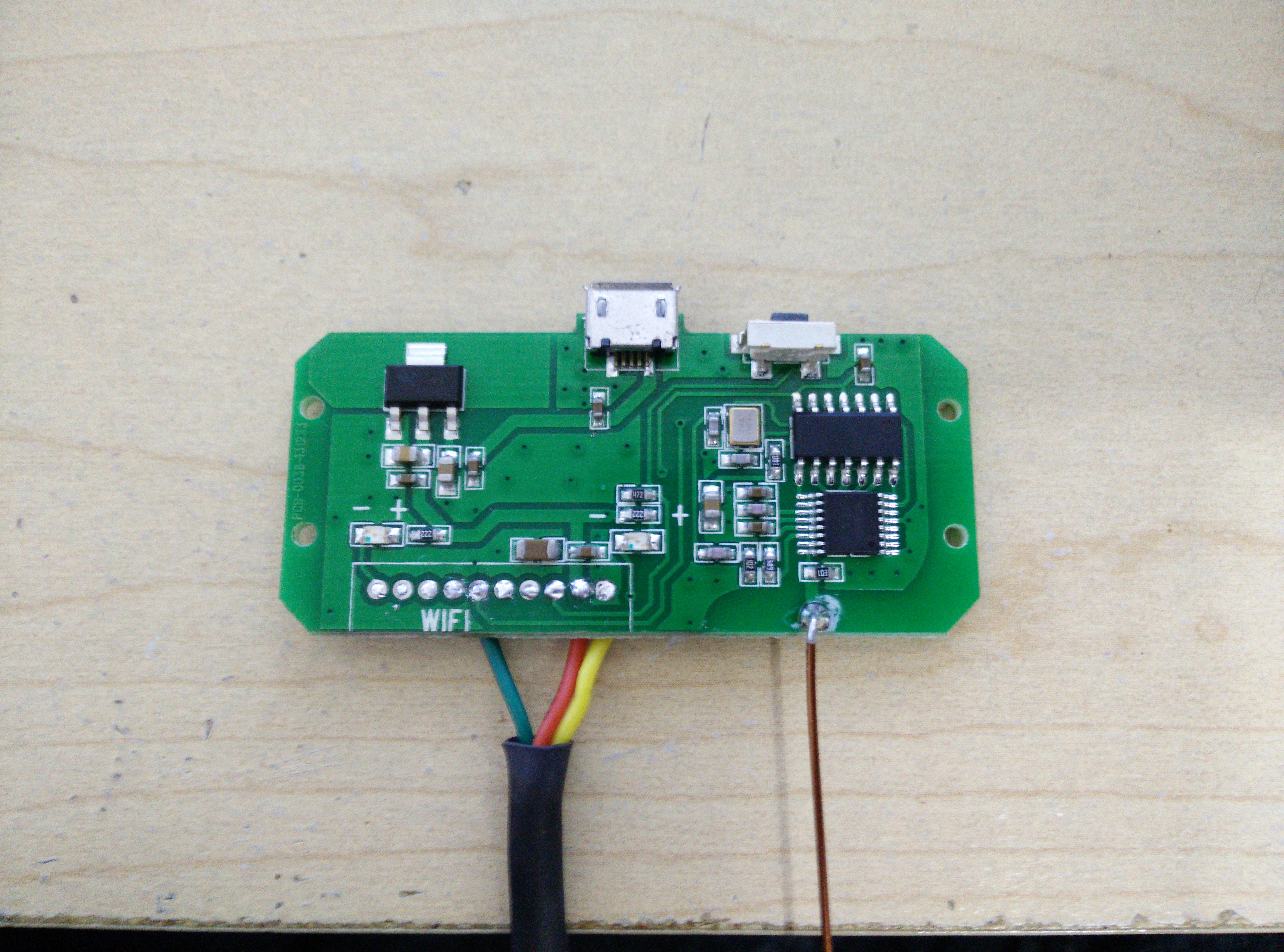
So with that, I decided the hell with it, and tore the sucker apart. Inside of the thing, you won’t find very much:
The mainboard (Ignore the cables, we will get to that later)
The WiFi Bridge
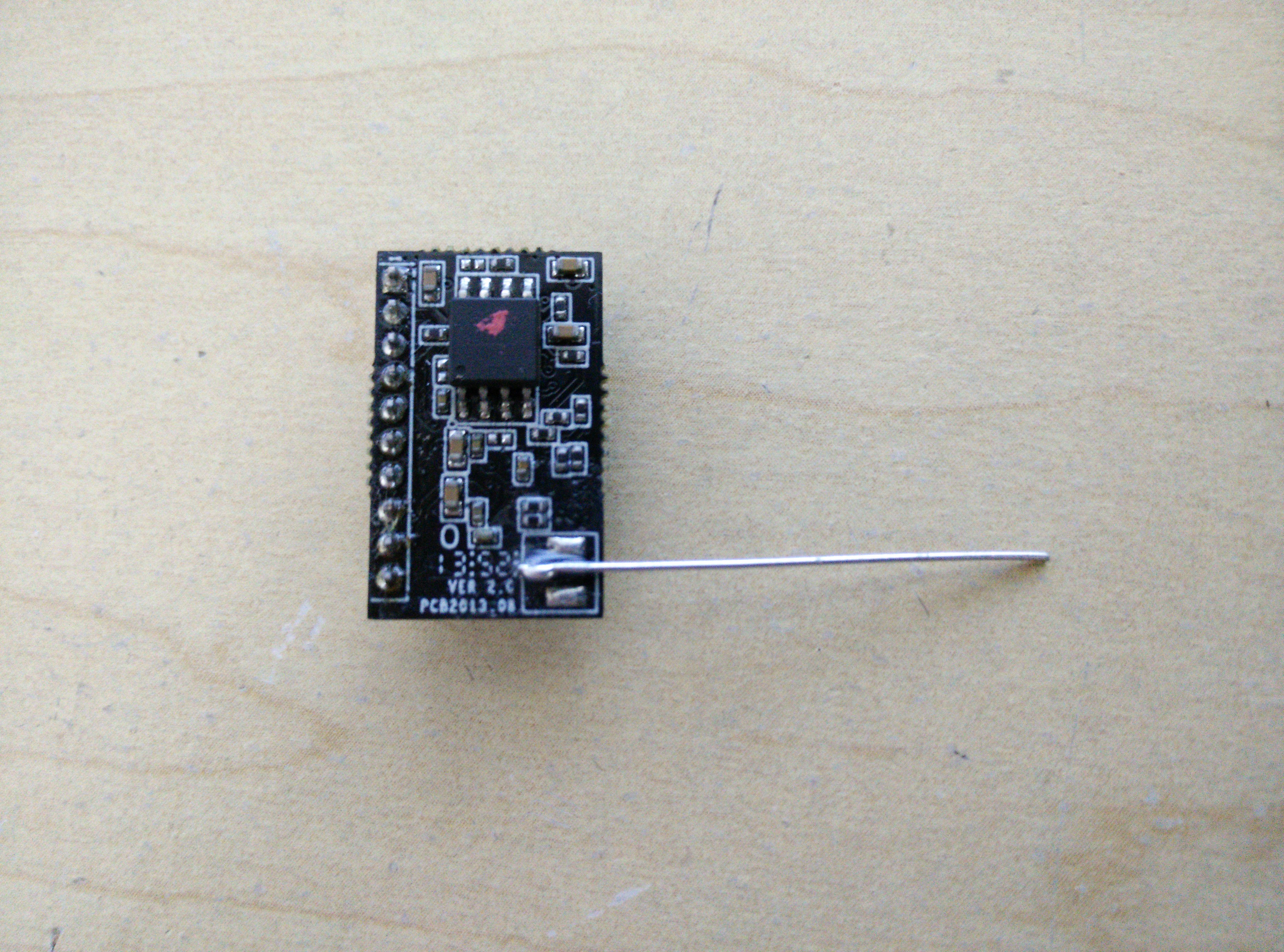
Now normally these are soldered together, but I forgot to take beforehand pictures (sorry!). So, at this point, I started by researching both boards. I was unable to find anything on the mainboard, but I found quite a bit of documentation on the WiFi controller, which is a High-Flying HF-LPT100 unit. With that, I was able to get a pinout for the leads and was able to find UART on pins 5 and 6. So using my new Saleae Logic 8 I decided to hook up to those leads and see if anything was coming across the leads.
So this is where it gets interesting. During boot and normal operation nothing is broadcasted over UART, and it does not seem to accept any input, but as soon as a command is sent to the controller to control my lights, the packet data was displayed in my serial session. So we can conclude from this that the packet data sent to control the LED’s is sent over the UART directly to the mainboard where it is converted and transmitted vi RF to the bulbs!
So to recap what we know:
- The WiFi bridge is powered by a basic HF-LPT100
- The bridge passes all UDP packets on port 8899 to the UART TX port (9600 baud)
- All UDP packets on port 48899 are used to interface with the HF-LPT100 (WiFi settings, etc)
- The RF radio listens on UART, forwards commands to LEDs
- Everything is powered by 3.3V
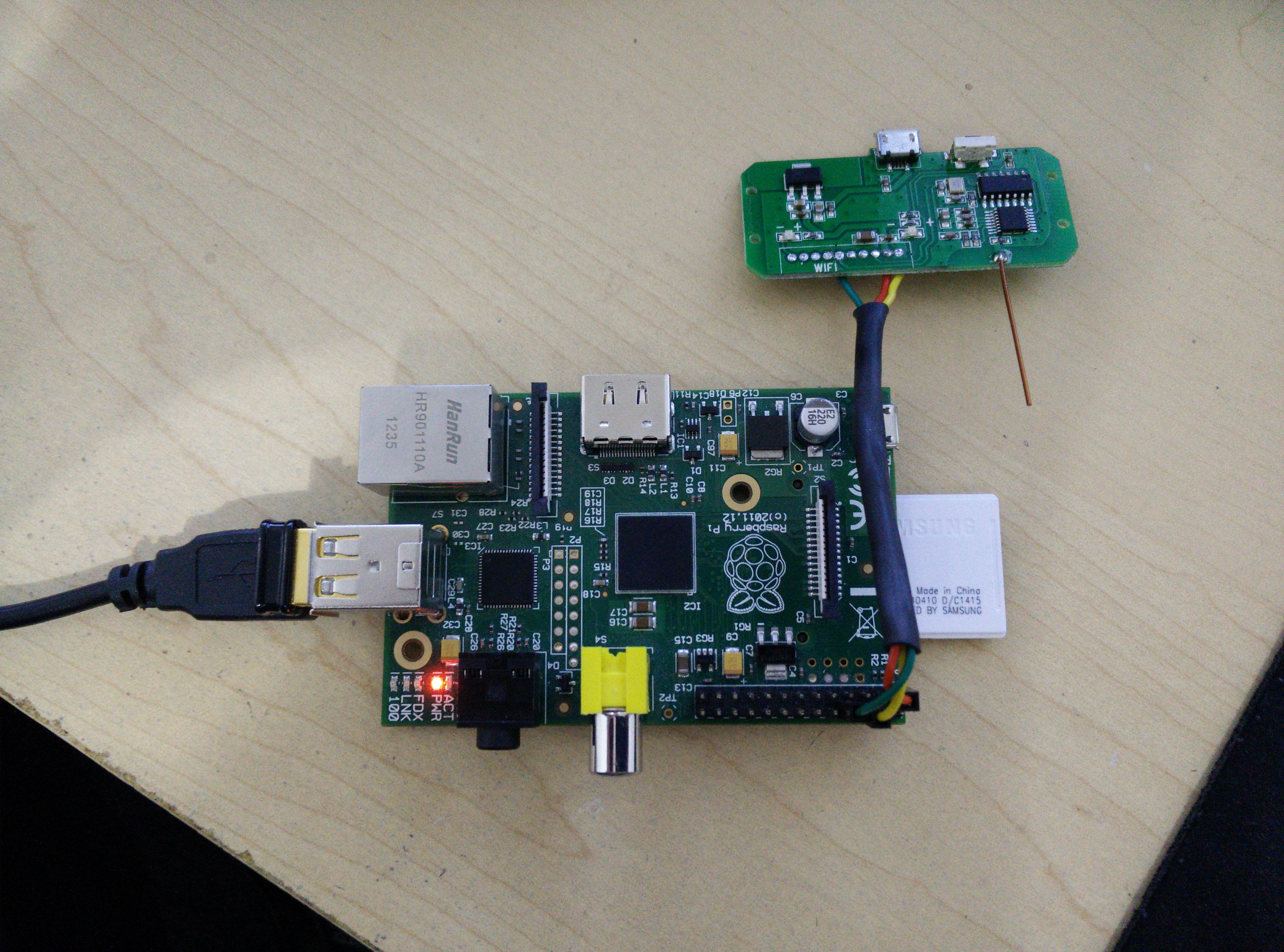
Now is where the fun starts. I soldered the WiFi receiver unit off of the mainboard, and hooked up the 3.3V, GND, and RX from the mainboard to a USB TTL device and opened a serial session on the interface. I then took the API Documentation from LimitlessLED, and mapped out the Hex value for “RGBW COLOR LED ALL OFF” to its ASCII character of A. I then turned the LEDs on in my room, sent A over my serial session… and the lights turned off! So from this I was able to confirm once again that the transmitter is directly using the UDP commands sent to the Wi-Fi receiver.
Now that everything was mapped, it was time to map it to the Raspberry Pi pinout. Here is the mapping I went with:
Pi to Transmitter
1 -> 2 (3.3V)
6 -> 1 (GND)
8 -> 6 (TX -> RX)
NOTE: If you do this you need to disable console from your Pi’s bootcmd, as you don’t want a console to be given over UART.
Once that was mapped, I tested again from the Raspberry PI to confirm things still work and as expected they did, but we still have some work to do. How do we go about getting native apps to work? Even better, how do we get it so the API documentation can still be used so all currently developed apps and API’s will run with this?
Well as the transmitter listens and runs off of raw UDP packet data, I coded up a little python listener to do the task! But wait, how about the auto discovery and setup in the iOS and Android apps? Don’t worry, that was taken care of as well! 🙂
Just download the source from my GitHub, change the variables to meet your requirements and hardware, run each script, and away you go!
And in the end, I now have a Raspberry Pi that controls my LED’s without any network issues, and works with Ethernet or WiFi!
First of all, thanks. My house is wired up with Milight and I had some Ardiuno set up that would kill the power to the bridge when it couldn’t be pinged, this “worked” but didn’t fix the issue.
I had my devices added to my bridge, so the following isn’t a huge issue for me, but I’m unable to get the admin.py to work. Under python 2.7 is doesn’t like the bytes command, so I ran it under python 3.2. I uncommented the prints and it seems to be sending the Pi’s IP and mac address out but it does;t show up in the Milight app, any ideas why?
Yeah, the scripts were designed for python 3+ so that is why it failed to run. As for the IP and mac address for the milight application, did you add your devices IP and MAC address to lines 10 and 11? If so, try wiping the application data for the Milight application on your device, and then try to re-scan for receivers. You may have to press it twice, but as long as you are on the same network it should work.
I added the Pi’s IP and MAC to lines 10 and 11, copied and pasted to ensure no mistakes. I print out what I’m sending and to what address, I see:
admin command: b’AT+Q\r’
admin command: b’Link_Wi-Fi’
admin return: 192.168.0.24, B827EB597AD8
(‘192.168.0.3′, 48899)
admin command: b’Link_Wi-Fi’
admin return: 192.168.0.24,B827EB597AD8
(‘192.168.0.3′, 48899)
admin command: b’Link_Wi-Fi’
admin return: 192.168.0.24,B827EB597AD8
(‘192.168.0.3′, 48899)
admin command: b’Link_Wi-Fi’
admin return: 192.168.0.24,B827EB597AD8
(‘192.168.0.3′, 48899)
admin command: b’Link_Wi-Fi’
admin return: 192.168.0.24,B827EB597AD8
(‘192.168.0.3’, 48899)
192.168.0.3 is the phone that’s running the milight app, 192.168.0.24,B827EB597AD8 is the IP and MAC of the Pi. I see that when the app tries to find the Pi it responds, but it only responds 5 times, is that correct? I removed the iOS and reinstalled it, what Milight app are you using? I can try that one as I have Android devices too. Thanks for your help.
Interesting… It should respond each time a request is made as there is no loop or timeout, so that might be a limitation of the Milight iOS application. Sadly I do not own any apple products, so I am unable to test. Everything I use is Android.
If you could, can you possibly get a packet capture of the Milight iOS app doing a handshake with the normal adapter? Then I can try to find what the variance might be and add it to the python script.
I’ll test it with Android tonight so that I can establish if it’s iOS/app to blame or the Pi.
I’ll also see if I can capture some extra info for you iOS side to give you an update. Thanks for your help with this.
Just to follow up, I’m at work at the moment but can now sniff UDP packets from my iOS device. I’ll search for an unmodified device as well as a modified device and send you the logs too, should deb quite easy to spot the difference. Do you have an email address I could get to send them to you?
Sure, feel free to send them to [email protected].
For the sake of the record, this has been resolved and the GitHub been updated with a fix.
Here is a video of the process from beginning to end: http://youtu.be/M_swGkuTqw4
Very very clever!
Thankyou for sharing.
I did a similar project last year. Instead of using a Pi i used a XPort Ethernet-to-TTL chip. Once configured, worked like a charm. No more drops or broken re-joins. Plain ethernet now! :/)
I steered everything from openhab.org which is just perfect to use. After contacting futlight the actual manufactor of milight and all mutants, saying that their wifi sucks, they rejected the idea of coming up with a ethernet (heck, even PoE) device. So I started my own and interest is increasing (with PoE).
Nice work! Much better to use a rpi for this, I plan to then use it to store the state of my lights on the pi too, so my other web apps can poll for current state/colour etc
Where you able to figure out what rf frequency it sends the commands to the lights on?
I’m thinking about doing the same.
Although I think it’s enough to just remember the on/off state since the lamps/led controllers remember the last used color and brightness.
Neatly done!
I would like to ask if you know how the RF module and the Wifi module are linked together on a software level. I’ve managed to update the firmware of my milight and now its not completely functional and a bit out of ideas how to proceed with the fix. I think I uploaded an official hi-flying firmware and that might have overwritten something what actually would be needed to communicate. (No app is identifying the wifi bridge).
Hello i would like to contact you about milight firmware do you have a firmware ?
Hey there,
Sadly I don’t as I re-flashed the HF-LPT100 with the latest stock/factory firmware, from the HF website.
David:
the wifi firmware is 100% stock. The one from the high-flying website has the same checksum as the one on the limitlessled sdk page..
So whatever is wrong it ain’t that. You should probably try re flashing over serial!
Wow nice work!
Seems like there are several 4.0 versions out there and my board looks like this:
https://www.dropbox.com/s/h5qbk1k3pvhiqkh/2015-02-06%2000.08.24.jpg?dl=0
Do you have any hints on this one? Tried to figure out the TX Pin with installed wifi board. Next step will be to unsolder it try it again…. maybe there are some labels on the back.
I recommend looking up the pinout of the Ralink wifi board, that should help you figure out the TX pin 🙂
Had to remove the wifi board…probably its serial connection to the transmitter was blocking the raspberrys connection: http://imgur.com/YiuHUc2
Pi to Transmitter
1 -> 2 (3.3V)
6 -> 3 (GND)
8 -> 4 (TX -> RX)
Great article, man! This is the first project that I see about reverse engineering the MiLight bridge. I have one request: could you please add a picture in which we can see which pin of the WiFi receiver is connected to which pin of the RPI? Thanks!
Hi guys,
I was hoping you could help me out. I’ve recently purchased exactly the same WiFi LED controller but my tablet is telling me port 48899 is unavailable. Do you have any idea why?
Alex
Great stuff! Just added a cheap USB to TTL converter to the milight bridge. I’m running your daemon and controlling several RGB bulbs with openHAB now. Thanks!
Hi,
Tonight I modded the Milight WiFi bridge as described in your article.
One thing I noticed after connecting to the Pi : The SYS LED doesn’t work anymore.
Could it be I broke the board ?
Anyway this happens when I search for a Milight device within the App :
root@raspberrypi:/usr/local/bin/rfled-server/RFLED-Server.git/trunk/source# python admin.py &
[2] 2442
root@raspberrypi:/usr/local/bin/rfled-server/RFLED-Server.git/trunk/source# (‘admin command: ‘, ‘AT+Q\r’)
Traceback (most recent call last):
File “admin.py”, line 31, in
adminsock.sendto(bytes(‘+ok’, “utf-8”),adminaddr) # Send OK for each packet we get
TypeError: str() takes at most 1 argument (2 given)
Any help is appreciated !
Cheers,
Bram
Hi Bram, I hav this issue, too.
Have anyone an idea why this happens?
I also notices that the Pin 6 is evenually the +Pin cause its descibed with a + in the layout.
Am I wrong?
Thanks for sharing this! I just performed the mod, tonight! Such a simple mod, for such a huge stability gain! My V1 Bridge has been going strong for 2+ years with no dropouts. The V4 Bridge has never worked properly, so this was a very welcome find!
Brilliant stuff
I have a V3 bridge that has worked without a glitch for 6+ months now
Wanted to add more zones but after going through three V4 bridges , I was ready to give up till i found this
Cherry on the cake – Just hooked up the main board to an existing RpI that was running xbian
Oh, forgot to add, this was a milight branded bridge brought in India
Thanks for sharing. Really a nice article.
Have you tried to go a step further and directly send the 2.4GHz WiFi signal? I have found, that the transmitter chip is a PL1167 and could communicate through SPI.
I first tried with a logic analyzer but looks a bit weired for me. Basically this chip can send or receive and is really cheep, so I ordered some of them to see how far I get.
But wondering if someone already tried this?
Did you ever try sending sending the signal directly
Great project. Doing it this way, are you still limited to controlling 4 groups as you are with the controller or does it allow you to expand the control group number?
I believe it would still be limited as that’s a part of the wireless board as far as I know.
OK. Thanks
I was looking to have a dozen or so bulbs in the house and the requirement of one hub per 4 lights (if you want to control each lamp individually) was a bit of a limit. Looks like it will still be a limit, but thanks for the reply.
Just got some help with the logic and the correct spec of the PL1167 (I had an old spec with wrong pinout). So sniffing SPI communication was possible.
The protocol seems simple. It’s not encrypted and seems to simply contain a 16bit controller ID.
The data contains a frame counter and is send around 50 times on 3 channels to “ensure” it’s received. I did not found any answers from the bulbs, so really seems to be a one way communication and the color really seems to only be 8bit (was hoping for a 24bit field internally).
The idea is to simply “emulate” multiple bridges by making the controller ID changeable.
I’m still waiting to receive my orde (5 chips for ~$15) to test sending own signals, will come back and post results of the tests, as soon as I have more info.
Hi Micha,
Great work. Please keep us posted on your results. I’d be very interested in seeing if this is possible. I was interested in doing something similar using a 3rd party zigbee radio, but I found out that the RF signal was encrypted (http://www.geekzone.co.nz/forums.asp?forumid=73&topicid=113569&page_no=29#1098355).
However, if it is possible to use your own PL1167, then that could be very interesting.
Hi,
I like this idea and would also to contribute if possible. I have also multiple bulps (74) and multiple led strips (40) controllers. Would avoid to have 30 bridged.
Is there any progress on the spi protocol?
Regards
Hi,
I first wanted to wait with the next response until I finished my tests. Unfortunately I’m currently stuck in work. So a short update.
I received the chips and soldered a first test one. It worked well. I was able to send signals from a PI through SPI to the chip and the bulbs accepted the signal. Additionally I confirmed that the bridge code is coded in the message. I’m not 100% sure, but I think it’s a 8bit bridge code. I successfully linked my test bulbs with two pseudo bridges.
Unfortunatelly I killed my first chip (not sure why/how) so I did not finished my tests.
I additionally ordered a pack of LT8900 chips, that should be compatible, but are much cheeper. I will send some more infos, as soon as I find some free time.
There’s a hackday project on the 2.4GHz Milight protocol : https://hackaday.io/project/5888/logs
Anymore on this topic was quite interested.
Thanks a lot!! .. it works great and so stable and fast!
So do I need a dedicated Pi for this, or can I run it directly from my exsisting home automation Pi?
Hi,
How can I fix this? I followed your instruction but when I want to connect trough the MiLight app this error shows up.
Traceback (most recent call last):
File "/home/pi/RFServer/listen.py", line 35, in
adminsock.sendto(bytes('+ok', "utf-8"),adminaddr) # Send OK for each packet we get
TypeError: str() takes at most 1 argument (2 given)
Hmm, that is strange. What version of Python are you using?
Hi
i just made tried your hack (awesome stuff) however i get an error message when starting rfled-server.
/etc/init.d/rfled-server start
root@freepbx:~/RFLED-Server-master# Traceback (most recent call last):
File “/usr/local/bin/led.py”, line 4, in
import serial
ImportError: No module named serial
the lights are not working either.
Any clue what this could be ?
Thanks
Very nice hack, thank you!
Works perfect on my Pi 2 parallel with FHEM for home automation.
Any idea how to use more then 4 channels on one bridge?
By the way, any idea how to fix this Error?
pi@raspberrypi ~ $ sudo /etc/init.d/rfled-server start
pi@raspberrypi ~ $ Traceback (most recent call last):
File “/usr/local/bin/admin.py”, line 17, in
adminsock.bind((UDP_IP, ADMIN_PORT))
socket.error: [Errno 98] Address already in use
Traceback (most recent call last):
File “/usr/local/bin/led.py”, line 17, in
sock.bind((UDP_IP, LED_PORT))
socket.error: [Errno 98] Address already in use
This guide is awesome, thanks heaps for putting this up.
I found after this conversion my lag from the app -> my lights was gone as well as my reliability problems being solved. They need to just sell them as a wired device and save everybody the trouble of fixing it themselves, but at least it works 100% now!
Thanks again!
Hello gents,
Sorry for a stupid question …. How can I register a bulb to the wifi box, without a smartphone ? I would like to use direct API to handle the bulbs. I ‘m testing a java and a PHP api … but something is still missing. I think that I should have a link (registration whatever) between wifi box and bulb.
Any suggestion ?
Many thanks.
Hello,
Normally registration is just done by turning on the outlet switch for the bulbs, and holding on the Power On option on a remote for the LED group you want the bulbs to be in, so technically this can be done by sending on the Power On command for a group over the API when you apply power to the bulbs from the socket. If I remember correctly, there is a 5~ second window to pair.
Many thanks for the quick reply. I have tried to send “on” command using java api and power on the bulb… unfortunately no success… might be a trick .. or I did something wrong.
Hmm, well normally you need to use one of the 4 group “On” commands, and not the master “on” command. May want to make sure you were sending the right “On” command to the LEDs.
Many thanks advising me !
Indeed, I was able to connect from api (based on Chris B advice) in the following way:
I did a loop, sending “on” command to a certain group (3 in my case) and then I have connected the bulb to the power supply, wait until 3 flashes.
No is all ok, I can switch on/off/change color, etc using java api.
One more thing.. I have noticed a network traffic between the wireless module and internet with the TCP frame bellow:
19:49:40.856003 IP 192.168.2.100.19814 > 208.113.204.254.38899: P 90:99(9) ack 1 win 1500
E..1……Yc…d.q..Mf…….4..P….<..Li_Link
Using AT commands (on port 48899) you are able to enable or disable functions, among that is something called "Cloud server" (TCP,38899,www.anymilight.com)
Any idea ?? how can I access it ? I suppose that might be a cloud features … but i'm not sure.
May thanks,
Hello,
Please i wanted to know if you know how to find in the web the official milight bridge firmware. because i updated the firmware with LPB-100 hi-flying download page but its a raw firmware so it doesnt support milight anymore 🙁
Thanks in advance
Best regards
Is there a way to identify which version the wifi controller is? There are different color labels used but it won’t disclose the version
Hi!
I love this Mod an had it running flawlessly on my RPI2 for some Time.
Now I changed to the new RPI3 and the bridge won’t work on a clean installation.
I did everything like last time, incl. disabling the serial console output.
I can find the bridge via smartphone app, but syncing the lights to the Channels won’t work as it used to.
Any idea what I can check or try to fix this?
Starting the script I am getting this:
pi@raspberrypi:~ $ sudo /etc/init.d/rfled-server start
pi@raspberrypi:~ $ Traceback (most recent call last):
File “/usr/local/bin/admin.py”, line 17, in
adminsock.bind((UDP_IP, ADMIN_PORT))
OSError: [Errno 98] Address already in use
Traceback (most recent call last):
File “/usr/local/bin/led.py”, line 17, in
sock.bind((UDP_IP, LED_PORT))
OSError: [Errno 98] Address already in use
Thanks for your help!
Martin
Hey Martin,
Did you update the admin.py and led.py script to bind to your new device’s IP and mac addresses? Normally the error you are seeing is a sign the service is already running, or is not configured correctly.
Hey Chris,
thanks for your quick reply.
admin.py has the correct IP and mac address and sits with led.py in /usr/local/bin/
####
eth0 Link encap:Ethernet HWaddr b8:27:eb:d5:be:e2
inet addr:192.168.1.69 Bcast:192.168.1.255 Mask:255.255.255.0
###
admin.py:
!/usr/bin/env python
import socket
# Set admin server settings
UDP_IP = ” # Leave empty for Broadcast support
ADMIN_PORT = 48899
# Local settings of your Raspberry Pi, used for app discovery
INT_IP = ‘192.168.1.69’
INT_MAC = ‘b827ebd5bee2’
# Code Starts Here #
.
.
led.py no changes.
Do I need to change anything else?
I did this once on my Raspi 2 and it worked out great. Did I forget anything?
Martin
Hmm, seems you are doing everything right, so you may just need to debug the error you are seeing. Normally this means something else is running on the port, as noted at https://stackoverflow.com/questions/17780291/python-socket-error-errno-98-address-already-in-use.
Also, this is running as root, correct? Also as the start script is in init.d, if you reboot the pi the services should automatically start at boot.
Hi Chris,
I started the script as root and I think it should be running on startup.
I checked init.d with grep -nrI Default-Start /etc/init.d:
/etc/init.d/rfled-server:7:# Default-Start: 2 3 4 5
Services with sudo service –status-all:
[ – ] rfled-server
Pins are connected like on my Raspi2 and the only thing running on it is FHEM.
So I don’t get it why the lights won’t pair to a channel as they used to.
Maybe something changed on Raspi3? Any idea what I can do to debug this?
Thanks for your help!
Martin
Hi Chris,
I did some more tests with the bridge.
1. I put it on a Raspi2 running jessie but it did not work
2. I tested a second bridge to rule out a technical defect but it did not work ether.
Do you have any clue why the bridge is not running on a Raspi3 with jessie?
What can I do to solve this?
Greetings, Martin
Hi guys, didn’t get it running on Raspberry 3 with jessie.
Anyone got it running on this system? Maybe there need to be something adapted because of device tree in jessie?
I am not good enough to figure this out by myself and would appreciate some help.
Martin
Hey Martin,
Sadly I don’t have a Pi 3 and I run this off of a Pi 1 B model, but if it helps I was able to get this going on Raspbian 8.0 using the following commands:
# Update, install packages, and clone repoapt-get update && apt-get dist-upgrade -y
apt-get install python python3 python3-serial -y
git clone https://github.com/riptidewave93/RFLED-Server.git /opt/RFLED-Server
# Edit the MAC/IP in /opt/RFLED-Server/source/admin.py
nano /opt/RFLED-Server/source/admin.py
# Remove ttyAMA0 (UART) Console in /boot/cmdline.txt
nano /boot/cmdline.txt
# Set permissions, and install files
chmod -R +x /opt/RFLED-Server/source
chmod +x /opt/RFLED-Server/rfled-server
cp /opt/RFLED-Server/source/led.py /usr/local/bin
cp /opt/RFLED-Server/source/admin.py /usr/local/bin
cp /opt/RFLED-Server/rfled-server /etc/init.d/
# Disable UART Console for good measure
systemctl disable [email protected]
systemctl stop [email protected]
# Enable new service
update-rc.d rfled-server defaults
update-rc.d rfled-server enable
# Away we go!
reboot
As for your error, have you made sure the service isn’t starting on boot already? (netstat -lnp | grep python)
Hi Chris,
thanks for your help.
I did everything exactly like you said, after clean removing my own installation (service & files) and reboot.
But it still won`t work 🙁
The service is running at startup and I can connect via App. But it is still not possible to sync individual bulbs with a channel.
Again I tested two bridges (one worked already with RPI2 wheezy) and double- and triple-checked the wiring.
I don’t know what else to do. Is there anybody who successful runs this on RPI3 with jessie?
Martin
Hi Chris & Martin,
I think I have a similar issue.
On my RPi model B (Raspbian Jessie) rfled-server is working, but it on my RPi 3 (also Jessie) it won’t
Here’s what I got so far:
– The serial port device for the RPi 3 is /dev/ttyS0 (instead of /dev/ttyAMA0)
– Indeed, if I configure led.py to use /dev/ttyS0, short GPIO 14 & 15 (pin 8 & 10 on the pinout) and `screen /dev/ttyS0`, I can observe the MiLight commands being sent.
– On the RPi3, the hardware UART of the Broadcom is used for Bluetooth. The GPIO 14/15 pins use a mini-uart port. The mini-uart clock is linked to the main CPU clock and is supposedly unreliable. (Source: http://www.briandorey.com/post/Raspberry-Pi-3-UART-Overlay-Workaround)
– So, my guess that timing is off or some other spec has changed, which is incompatible with the MiLight bridge. Unfortunately, I don’t have any hardware to inspect the actual output of the UART port.
– A workaround could be to disable Bluetooth en remap the hardware UART to the GPIO pins (see link above). However, I’d like to use bluetooth as well for another project.
Chris, any ideas/other tests I could try?
Kind regards,
Marcel
Hey there,
Thanks for the awesome info! As for a work around, you can always try adding a USB UART adapter, and then wiring that directly to the MiLight board. This will allow you to have the hardware UART for Bluetooth, and a UART adapter is cheap at around $5 shipped.
Hi guys,
I am very happy someone has the same problems. No offense… 😉
But this looks like a good plan to solve this.
Today I ordered a PL2303 USB UART Board and will do some tests when it arrives.
Martin
Hi,
disabling Bluetooth and remapping UART works also.
Found this on openenergymonitor.org:
To disable onboard Pi3 Bluetooth and restore UART0/ttyAMA0 over GPIOs 14 & 15 modify:
sudo nano /boot/config.txt
Add to the end of the file
dtoverlay=pi3-disable-bt
We also need to run to stop BT modem trying to use UART
sudo systemctl disable hciuart
Runs like a charm with no extra hardware 🙂
Hello
I’ve a raspberry B+…the scripts are working fine (debugging by print and testing with an iOS app) but I have to pair again my lights…and I try to do it with the app and it just does not work : the light do not blink whtn I push the on button on one channel…
Is there something special to be done?
Hi all,
great stuff here. Thank You Very Much !
I like the former python script, and I can get a fine “go” solution here, now to.
Maybe it’s a little bit of topic, because I use a FritzBox (Router) with FTDI chip,
instead of the Raspi and the FritzBox with freetz has not that much memory.
Therefore I installed socat over freetz, and the ftdi driver, too.
Then I put the following stuff to my freetz -> rc.local.
#!/bin/bash
SERIALDEVICE=ttyUSB0
cat > /tmp/milightresp.sh << 'EOS'
#!/bin/bash
#change ip and mac according to your device
INT_IP='192.168.178.1'
INT_MAC='x8x423x95f9x'
read -t1 -N10 VAL
if echo "$VAL" | grep -q 'Link_Wi-Fi'
then
echo $INT_IP,$INT_MAC,
else
echo +ok
fi
EOS
chmod +x /tmp/milightresp.sh
socat -v udp-l:48899,fork exec:'/tmp/milightresp.sh' &
socat -v -b2 udp-l:8899,fork,reuseaddr file:/dev/$SERIALDEVICE,b9600,raw &
Have fun !
Hello,
I am an industrial designer that has been using the milights in some wall art projects. I can run the devices off the remote, but cannot get the wifi bridge to work. I came across your posting, but I have no experience with Rasberry Pi devices. Would it be too much trouble to ask for a dumbed down version of this guide (complete with photos, and a detailed shopping list).
Thanks!
Hi,
Thank you for this.
I tried to install version 1.1 of rfled-server on my Raspberry Pi 2, but when I run systemctl enable rfled-server, I get the following error:
Failed to issue method call: Invalid argument
Any idea what the issue could be?
Thanks in advance!
This is a systemd message that it’s unable to enable the service, so you may need to modify the service file for the OS you are using on your Pi. https://bbs.archlinux.org/viewtopic.php?id=152950
Thanks Chris!
It works now 🙂
Hello,
I tried to follow each step of the topic and it works well using the default serial port /dev/ttyAMA0.
I’m using AMA0 serial port for another project so I tried to connect a USB TTL (like this one : https://cdn.instructables.com/F0L/DZH2/HFD1F0NF/F0LDZH2HFD1F0NF.MEDIUM.jpg).
I detected the USB TTL as /dev/ttyUSB1 when I plugged it to raspberry.
But I was not able to replace the default serial port /dev/ttyAMA0 by /dev/ttyUSB1 in your program … :/
Can you help me ?
Thanks a lot 😀
If you are running the Go binary, you can change the UART port by using the application flags.
Example:
rfled-server -serial /dev/ttyUSB0 -baud 115200As mentioned in the Repo Readme, you can add the flags to /etc/default/rfled-server so they are ran if you are running this as a service.
I tried this command it works : rfled-server -serial /dev/ttyUSB0 -baud 115200
So in /etc/default/rfled-server I added “RFLED_OPTS= -serial /dev/ttyUSB0”
When I tried “/etc/init.d/rfled-server start” it says : “/etc/init.d/rfled-server: 6: /etc/default/rfled-server: -serial: not found”
Maybe I made a mistake in the option file ?
Hey,
You will want to make sure that your file has a line similar to the following:
RFLED_OPTS=” -serial /dev/ttyUSB0”, as having the entire line in quotes will cause the issue you are seeing.
It works well after the modification, I needed to add quotes …
Thank you very much 😀
Hello I am getting the error:
pi@raspberrypi:~/rfled-server $ sudo rfled-server
2016/10/05 07:44:34 too many colons in address fe80::497b:4d29:59e:2d6c:8899
Any help?
thanks
Hello,
Seems the app is binding to the IPv6 address of your interface. You will want to try to manually set it to use IPv4 by specifying the IP.
./rfled-server -ip xxx.xxx.xxx.xxxThis setting is defined at https://github.com/riptidewave93/RFLED-Server/blob/master/src/rfled-server.go#L92 for reference.
I had this same problem. Did you set it up on one network interface then switched to another later?
I had this same issue when I switched from eth0 to my wireless interface. It worked after I switched back. If you do a clean install you can go WiFi with no issues, switching to eth0 causes the issue to come back.
Hope this helps!
Do you know if this setup will allow me to control the following bulbs?
https://www.amazon.de/gp/product/B00KYYL9BG/ref=oh_aui_detailpage_o02_s00?ie=UTF8&psc=1
https://www.amazon.de/gp/product/B00YMRQFX8/ref=oh_aui_detailpage_o02_s00?ie=UTF8&psc=1
Hello,
I can’t confirm for sure, but those look exactly like the LEDs I personally use so there is a high chance they will work.
The one without coulours has is a combined “warm white” / “cold white” LED. Do you also use them?
I tried to control them directly using an nRF24L01+ as described here:
http://torsten-traenkner.de/wissen/smarthome/openmilight.php
But I did not succeed. My guess is that my bulbs use a different protocol (I read about differences of the protocols between different MiLight bulbs, but do not recall the reference right now). So I wonder if this very difference might also cause problems using your approach or if it is more universal due to the partial use of the bridge.
Hey there,
As my code only emulates the WiFi bridge and not the transmitter, as long as your LED bridge uses the same ports then this method should still work for that version of the LEDs, but I do now own one of those combined mode lights to verify this for sure. In theory it “should” work as my approach does not mess with, or change the packet structure of data sent to the LEDs.
has anyone tried to adapt the led server code so you don’t need to salvage the radio out of a gateway, but just hook up an nrf24l01?
Completed the soldering no problems using the exact same WiFi bridge as you on a Raspberry Pi. Did a clean restore to the latest Raspberrian.
I run the following commands:
sudo apt-get install update && sudo apt-get install upgrade
sudo apt-get install golang
sudo apt-get install git-all
git clone https://github.com/riptidewave93/RFLED-Server.git /opt/RFLED-Server
Then I try to follow your input below, but nano brings up “blank” documents, and I believe I’m failing to install RFLED-Server correctly. Would you mind posting the exact steps on a Rapsberry Pi for a total linux noob? Greatly appreciate the insight and this blog post, very cool! 🙂
# Edit the MAC/IP in /opt/RFLED-Server/source/admin.py
nano /opt/RFLED-Server/source/admin.py
# Remove ttyAMA0 (UART) Console in /boot/cmdline.txt
nano /boot/cmdline.txt
# Set permissions, and install files
chmod -R +x /opt/RFLED-Server/source
chmod +x /opt/RFLED-Server/rfled-server
cp /opt/RFLED-Server/source/led.py /usr/local/bin
cp /opt/RFLED-Server/source/admin.py /usr/local/bin
cp /opt/RFLED-Server/rfled-server /etc/init.d/
Can’t get passed this point. Appreciate anyones input on where I’m going wrong, very new to Linux.
Hello,
From the commands you shared, it looks like you did it right but now that Go is used, those install instructions are no longer valid. To install the Go version of the service, you will want to download the release .tar.gz which is on the Releases page on GitHub, which will provide a compiled version of the application. One done, follow the install info in the Readme of the repo. https://github.com/riptidewave93/RFLED-Server
Working fine with both the RGBW and plain white ones on my Pi2.
You can go a tiny bit further and hack off the USB port to save some space, literally just chopped it off. The whole thing can fit neatly inside a Pi2 case: http://imgur.com/gallery/pLGUM
Now we just have to wait for the V6 bridge to come out (able to control the new RGBWWCW bulbs) and hope this mod still works!
Hello
what is the exact AT Command set for v4.0 limitlessled wifi bridges? it seems the API guide at the following url don’t work! pls hlp!
AT commandset
+ok\r //enter admin mode
AT+WSCAN\r
+ok= detected WIFIs…
AT+WSSSID=mySSIDname\r
+ok
AT+WSKEY=WPA2PSK,AES,password123\r
+ok
AT+WMODE=STA\r
+ok
AT+Z\r
+ok
AT+Q\r //exit admin mode
Great article! Thought I would let you know that I just received the v6 bridge, and it seems to use the same wifi controller:
http://i63.tinypic.com/zxwpas.jpg
Where did you get hold of a V6 bridge?!? Been waiting for that thing to come out so that I can get RGBWWCW bulbs.
I got one from a dutch MiLight webshop. But I’ve also seen them on alibaba.
It’s sold as ‘Wifi iBox’ under the Milight brand, but I haven’t seen it with the other brand names yet.
Works like a charm on my RGB+CCT downlights. I’m now trying to hook it up to an Arduino, trying to figure out what commands I have to send.
There is some guys who have built a fake wifi bridge here. Might be worth a shot to use.
ESP8266 + nRF24L01
Have not tried it but i will when i get a nRF24 😀
https://github.com/csowada/openmili
Hi Chris. Thank you for a great job for emulating the MiLight bridge.
I have a weird problem that I hope I can get som help with. When I reboot the RPi v.1 it starts the rfled-server service as shown below:
pi@milightrpi:~ $ sudo service rfled-server status
● rfled-server.service – LSB: RFLED-Server for Milight LEDs
Loaded: loaded (/etc/init.d/rfled-server)
Active: active (exited) since Sun 2016-10-30 14:39:01 CET; 34s ago
Process: 332 ExecStart=/etc/init.d/rfled-server start (code=exited, status=0/S UCCESS)
Oct 30 14:38:59 milightrpi systemd[1]: Starting LSB: RFLED-Server for Milig…..
Oct 30 14:39:00 milightrpi rfled-server[332]: Starting rfled-server: rfled-s….
Oct 30 14:39:01 milightrpi systemd[1]: Started LSB: RFLED-Server for Miligh…s.
Hint: Some lines were ellipsized, use -l to show in full.
BUT it doesn´t show the service on the MiLight iOS app. Therefor I stop the service:
pi@milightrpi:~ $ sudo service rfled-server stop
Check the status:
pi@milightrpi:~ $ sudo service rfled-server status
● rfled-server.service – LSB: RFLED-Server for Milight LEDs
Loaded: loaded (/etc/init.d/rfled-server)
Active: inactive (dead) since Sun 2016-10-30 14:40:25 CET; 2s ago
Process: 662 ExecStop=/etc/init.d/rfled-server stop (code=exited, status=0/SUCCESS)
Process: 332 ExecStart=/etc/init.d/rfled-server start (code=exited, status=0/SUCCESS)
Oct 30 14:38:59 milightrpi systemd[1]: Starting LSB: RFLED-Server for Milight LEDs…
Oct 30 14:39:00 milightrpi rfled-server[332]: Starting rfled-server: rfled-server.
Oct 30 14:39:01 milightrpi systemd[1]: Started LSB: RFLED-Server for Milight LEDs.
Oct 30 14:40:25 milightrpi systemd[1]: Stopping LSB: RFLED-Server for Milight LEDs…
Oct 30 14:40:25 milightrpi rfled-server[662]: Stopping rfled-server: rfled-serverstart-stop-daemon: warning: failed to kill 371: No such process
Oct 30 14:40:25 milightrpi rfled-server[662]: .
Oct 30 14:40:25 milightrpi systemd[1]: Stopped LSB: RFLED-Server for Milight LEDs.
And then start the service again:
pi@milightrpi:~ $ sudo service rfled-server start
pi@milightrpi:~ $ sudo service rfled-server status
● rfled-server.service – LSB: RFLED-Server for Milight LEDs
Loaded: loaded (/etc/init.d/rfled-server)
Active: active (running) since Sun 2016-10-30 14:40:36 CET; 2s ago
Process: 662 ExecStop=/etc/init.d/rfled-server stop (code=exited, status=0/SUCCESS)
Process: 707 ExecStart=/etc/init.d/rfled-server start (code=exited, status=0/SUCCESS)
CGroup: /system.slice/rfled-server.service
└─717 /usr/sbin/rfled-server
Oct 30 14:40:36 milightrpi rfled-server[707]: Starting rfled-server: rfled-server.
Oct 30 14:40:36 milightrpi systemd[1]: Started LSB: RFLED-Server for Milight LEDs.
And this time the service shows in the MiLight iOS app as a bridge.
The only difference I see in the two service status´ is the CGroup: /system.slice/rfled-server.service
└─717 /usr/sbin/rfled-server
So it seems that the RPi doenst start the correct service on startup/reboot but when the user stops and starts the service it starts the correct service.
Im thinking this is a NOOB problem but Im going nuts because I cant solve it. So any help would be much appriciated 🙂
I am having this exact same issue. No solution yet except to stop/start the service.
Maybe off-topic, but you guys seem to have a lot of knowledge of this crappy Mi-light wifi box 🙂
My mi-light bridge stopped working ( did not do anything with it. plugged it in right from the box and it worked for a year an d a half. Now both sys & link leds are off. Whem i plug it in a small tiny flash of both leds and then dead again. Can this be repaired ? I can solder..
All hints apriciated
Regards from The Netherlands, RadioRon.
Hello,
Sadly sounds like either the power circuitry on the main PCB is toast, or the actual wifi bridge unit is dead. Sadly the only way to check is to diagnose each part. For example, if you use jumpers to apply 3.3v to the wifi bridge manually does it boot then without issue?
What version of raspberry pi did you use?
I’m using a 3 and I see that it is causing problems so I plan on getting a earlier model, which one did you use? Pi1, pi2?
Hello,
For my project I repurposed an older Pi1. As for the issue, most issues with the Pi3 are due to the fact that the actual hardware UART is used for the bluetooth modem. You may want to try using the following to see if it helps resolve your issues. https://raspberrypi.stackexchange.com/questions/45570/how-do-i-make-serial-work-on-the-raspberry-pi3
Specifically in that post, the parts about the device tree to swap back the UARTs.
Hi,
I want to run it on a RPI3 with Jessie. I already have set up the interfaces as described here:
http://spellfoundry.com/2016/05/29/configuring-gpio-serial-port-raspbian-jessie-including-pi-3/
I followed the installation steps on https://github.com/riptidewave93/RFLED-Server
The options in /etc/default/rfled-server are set to: RFLED_OPTS=” -serial /dev/ttyAMA0”
As I want to enable the server it doesn’t work:
(#)~:$ systemctl enable rfled-server 17:44:11
Synchronizing state for rfled-server.service with sysvinit using update-rc.d…
Executing /usr/sbin/update-rc.d rfled-server defaults
insserv: script rfled-server is not an executable regular file, skipped!
Executing /usr/sbin/update-rc.d rfled-server enable
update-rc.d: error: no runlevel symlinks to modify, aborting!
[Exit 1 ]
(#)~:$
May you help?
Hello, i am a newbie on raspberry
but i think i got everything working only i dont see any milight box in the app on my phone
what do you meen with: Configure your settings in /etc/default/rfled-server as needed
where can i find these settings, i dont know my wifi box mc asdres nor ip adress.
Raspberry pi2 is running on ip 192.168.1.53
when i start; 4. Enable the init.d script systemctl enable rfled-server
its says:
executing /usr/sbin/update-rc.d rfled-server defaults
executing /usr/sbin/update-rc.d rfled-server enabled
And than:
5. Start the service service rfled-server start
it coms back with nothing ??
please help
This is normal. You should see a server through your app now if you’re on the same lan your pi is.
Okay. So I’m having issues here…
The first issue is that it is not starting up on the startup. I’ve done a fresh install 3 times now (fully new OS), and on the first setup inputting the commands….
sudo systemctl enable rfled-server
sudo service rfled-server start
…creates a milight server visible to my phone which I can connect to. However when I restart (and every time I restart after) the server does not automatically start up. Even more troublesome, the commands
sudo systemctl enable rfled-server
sudo service rfled-server start
don’t start the server again and my phone can’t connect.
I’ve solved this by manually inputting
sudo rfled-server – debug
This gets the server up and running and is visible to my phone, even better I can see that the app is talking to the server nicely. But… there’s still issues. I’ve burned through 2 bridges now and neither are forwarding the commands onto the bulbs. I have been unsuccessful in pairing a bulb to the bridge thus far. I strongly suspect that there’s something wrong with my hardware, but I cannot pinpoint what.
So I have a few questions. How can you view the output to the serial connections so I know the server is forwarding it’s commands properly, and what should I look for in the bridge? I’m reasonably certain there are no shorts, and I know I got the pins right, I matched it to the picture above (I’m on a pi 2b, and could take a picture of the bridge if it helps).
Any help at all would be appreciated. I’m banging my head against the wall metaphorically.
And another point…
I’m seeing others mention admin.py files and such, yet I see no such file in any of the tar.gz area nor do I see them after installation. Am I missing files?
Okay, so sorry about the string of comments from me but I figured I’d update what I found out just from my own further troubleshooting. Still nothing sadly :-/
First, after browsing these comments I found someone who had the same issue as me in that the service is not auto starting and we both have the issue fixed by issuing the commands
sudo service rfled-server stop
sudo service rfled-server start
Not a permanent ideal solution, and this has happened on 3 consecutive fresh installs of raspbian at this stage for me (on a pi 2b+).
This does create a server which my phone connects to, and I’m confident the commands are being received because debugging is super responsive when I’ve run it, and the activity light is doing its thang.
I’ve taken a multi meter to 1, 2, 6 on the wifi bridge and one of the known grounds on the PI, I’m reading 3.3volts to each. I have no idea how to read any output from the data connection, or any wireless output from the remotes.
If anyone, and I mean anyone has any means of helping me out here I’d be forever in your debt.
Used an arduino in serial monitor mode.
Commands are not being sent from Pi’s serial. Receiving input fine though. Please advise, I’m honestly at a brick wall.
Interesting article.
So were you able to improve the speed commands are sent? I’d like to control the rate at which my lights dim but the only solution I’ve found has been to send numerous brightness commands and I don’t feel this is ideal. For starters, sometimes some commands get lost to the ether, and there appears to be a required delay of a noticeable amount of milliseconds (I think 20) between each command so I can not achieve the true smooth dimming that I want.
I wonder if by passing wifi is the solution to my problem.
Hello Chris,
what about to rewrite your code to use the NRF24L01+ together with the PI?
It would help so many people out here..
Please consider it.
Just wanted to thank you for this excellent software and guide. After struggling with intermittent lights for almost 4 years I finally have a dependable system! Some notes for others who follow:
-The current version requires systemd so that’s Raspbian Jessie at the least. Wheezy won’t work – you must upgrade.
-the armv6 version is for original Pis. My Pi2 rev 1 model B took the armv7 binary. The 64-bit binary is for newer.
-Removing the old WiFi board is by far the most difficult step. Removing *all* the solder so it’s loose, then lifting it straight off the pins so it doesn’t bind, is virtually impossible with a conventional soldering iron and only two hands. I ended up cutting the pins flush and then ripping it off after I removed as much solder as I could. Don’t worry about damaging the pins too badly because they also extend out the underside so you can attach your wires there. Just make sure nothing’s shorted.
-Pin 1 is the inside pin.
-This works very well with the milight utility (http://iqjar.com/jar/home-automation-using-the-raspberry-pi-to-control-the-lights-in-your-home-over-wi-fi/) just put your Pi’s IP address in the milight.conf file. local address – 127.0.0.1 – doesn’t seem to work.
Here you can get a full bridge replacement with MQTT-Integration und state awareness. Just get an esp8266 and a NRF24L01 transceiver. This little project can emulate as many bridges as needed and provides a own REST API.
https://github.com/sidoh/esp8266_milight_hub
Anyone know if this works with v6 wifi controller?
thanks.
Looking for professional photo editing tools? You’ve come to the right place!
We provide the latest design tool directories to help you find the best platforms for professional designs.
Explore the top design software options for 2023, carefully selected for functionality and reliability.
Join a community of creativity-focused users and access top-rated photo editing tools today.
Whether you’re looking for professional-grade performance, our guide of design software ensures a efficient experience.
Perfectly said, this is exactly what I was looking for!
https://www.quora.com/profile/Christopher-Johnson-3-2/Dive-into-professional-design-with-photoshop-crack-download-today-This-top-tier-software-offers-a-comprehensive-set-of
crack photoshop free download
Appreciating the commitment you put into your blog and detailed information you offer. It’s awesome to come across a blog every once in a while that isn’t the same unwanted rehashed material. Fantastic read! I’ve saved your site and I’m including your RSS feeds to my Google account.
I am regular reader, how are you everybody? This post posted at this website is really nice. http://www.51Z1z.cn/comment/html/?65869.html
мостбет download ios [url=https://www.mostbet07541.help]https://www.mostbet07541.help[/url]
mostbet nyerőgépek RTP [url=www.mostbet26815.help]www.mostbet26815.help[/url]
kg5u6b
pokerstars crazy time [url=http://www.crazy-time-italy.it/]https://crazy-time-italy.it/[/url]
[b]Лучшие площадки 2026: актуальный рейтинг[/b]
Редакция dark-net.life представляет актуальный рейтинг проверенных площадок на февраль 2026. Каждая из площадок регулярно мониторятся — только рабочие адреса. Добавьте в закладки — адреса обновляются.
Перед вами обзор сайтов с рабочими ссылками. Переходите по ссылке под названием магазина.
[hr]
[b]1. LoveShop[/b] ★★★★☆
Один из старейших магазинов — 250+ городов. Сверяйте ссылки на Rutor.
Надёжная площадка — loveshop, лавшоп, loveshop biz, loveshop tor, loveshop зеркало, loveshop1, loveshop2, loveshop12, loveshop13, loveshop1300, loveshop18, ссылка лавшоп
[b]Зеркало:[/b] [url=https://loveshop13.site]loveshop18.top[/url]
[b]2. Orb11ta[/b] ★★★★☆
Давно проверенная площадка — широкая сеть доставки. Один из лидеров.
Надёжная площадка — orb11ta, orb11ta com, orb11ta vip, orb11ta сайт, orb11ta top, orb11ta org, orb11ta ton, орбита бот, https orb11ta site, orb11ta com сайт вход
[b]Зеркало:[/b] [url=https://orb11gram.lol]orb11ta.sbs[/url]
[b]3. Chemical 696[/b] ★★★★☆
Работает без перебоев — chemical 696 biz официальный. Проверен на форумах.
Проверенный магазин — chem696, chemical696, chemi696, chemi to, chemshop2 com, chm696 biz, chm1 biz, chemical 696 biz официальный, чемикал 696, чемикал биз, chmcl696
[b]Зеркало:[/b] [url=https://chemshop-2.com]chm1.top[/url]
[b]4. LineShop[/b] ★★★★☆
Работает стабильно — lineshop 24. Актуальные зеркала.
Рекомендуем — lineshop biz, lineshop 24, lineshop biz 24, lineshop blz, лайншоп, ls24 biz, ls24 biz официальный, ls24 biz официальный сайт, ls24 махачкала, ls24 blz, ls25 biz, ls24 bis
[b]Зеркало:[/b] [url=https://lineshop.icu]ls24.shop[/url]
[b]5. TripMaster[/b] ★★★★☆
Проверенная площадка — tripmaster официальный. Рекомендован пользователями.
Надёжная площадка — tripmaster to, tripmaster biz, tripmaster официальный, tripmaster 24, tripmaster ton, tripmaster biz проверка заказа, tripmaster24, tripmaster24 biz, mastertrip24 biz, tripmaster24 diz
[b]Зеркало:[/b] [url=https://tripmaster.info]tripmaster.live[/url]
[b]6. Syndi24[/b] ★★★★★
Синдикат — проверенная площадка — syndicate 24 biz. Актуальные зеркала.
Топ выбор — syndi24, syndi24 biz, syndi24 bz, синдикат 24, синдикат бот, синдикат шоп, синдикат сайт, синдикат официальный сайт, syndicate 24 biz, syndicate biz, syndicate one, syndicate 24 4 biz зеркала
[b]Зеркало:[/b] [url=https://syndi24.sale]syndi24.sale[/url]
[b]7. Narco24[/b] ★★★★☆
Стабильная площадка — narco24 biz официальный. Широкая география.
Надёжная площадка — narkolog, narkolog ru, narkolog biz, narkolog 24 biz, narkolog me, narco24, narco24 biz, narco24 biz официальный, narco24 официальный сайт, narcolog24, narcolog24 biz, narco 24, narco 24 biz
[b]Зеркало:[/b] [url=https://narcolog.vision]narcos24.pro[/url]
[b]8. Tot[/b] ★★★★☆
Надёжный сайт — tot777 ton. Проверено редакцией.
Надёжная площадка — black tot, bbt007, bbt007 com, bbt777 biz, bbt777 to, ббт777, tot777, tot777 ton
[b]Зеркало:[/b] [url=https://bbt777.click]tot777.top[/url]
[b]9. BobOrganic[/b] ★★★★★
В гостях у боба — проверенный магазин — boborganic biz. Широкая география.
Рекомендуем — boborganic to, boborganic biz, boborganic ton, боб органик, в гостях у боба, в гостях у боба тг, в гостях у боба сайт, в гостях у боба магазин, в гостях у боба омск, в гостях у боба новосибирск, tonsite boborganic ton
[b]Зеркало:[/b] [url=https://boborganic.shop]boborganic.shop[/url]
[b]10. BadBoy[/b] ★★★★★
Стабильный магазин — badboy ton. Рабочий вход.
Проверенный магазин — badboy96, badboy96 biz, badboy ton, badboy, badboysk, badboy999
[b]Зеркало:[/b] [url=https://badboy96.click]badboy96.shop[/url]
[b]11. Kot24[/b] ★★★★☆
Надёжная площадка — kot24 biz. Актуальные зеркала.
Надёжная площадка — kot24, кот24, мяу маркет, kot24 biz, kot24 com, kot24 cc, kot 24
[b]Зеркало:[/b] [url=https://kot-24.com]kot-24.com[/url]
[b]12. Megapolis2[/b] ★★★★☆
Проверенная площадка — megapolis 2 com. Проверено.
Стабильная работа — megapolis2, megapolis2 com, megapolis com, megapolis 2 com
[b]Зеркало:[/b] [url=https://megapolis2.sale]megapolis2.click[/url]
[b]13. Stavklad[/b] ★★★★★
Стабильная работа — stavklad biz. Проверено редакцией.
Надёжная площадка — stavklad, stavklad com, www stavklad com, stavklad biz, sevkavklad biz, sevkavklad to, sevkavklad com, магазин прош
[b]Зеркало:[/b] [url=https://stavklad.app]stavklad.click[/url]
[b]14. Sberklad[/b] ★★★★☆
Проверенная площадка — купить лирику без рецепта. Рекомендован пользователями.
Стабильная работа — sberklad biz, sbereapteka, sbereapteka biz, sber eapteka, лирика краснодар, лирика пятигорск, лирика нальчик телеграм, купить лирику краснодар, лирика без рецепта краснодар, купить лирику в краснодаре без рецепта, лирика таблетки 300 где купить в краснодаре, лирика махачкала, ростов на дону лирика, купить лирику ростов на дону
[b]Зеркало:[/b] [url=https://sberklad.info]sberklad.click[/url]
[hr]
[i]Источник: dark-net.life — актуально на апрель 2026. Добавьте в закладки — ссылки актуальны сейчас.[/i]
crazy time italia tracker [url=http://www.crazy-time8.com]https://crazy-time8.com/[/url]
crazy time status [url=http://www.crazy-time-italian.com/]https://crazy-time-italian.com/[/url]
[url=https://www.instagram.com/emproconstruction?igsh=NzdkYWJ4d2NvNHU1&utm_source=qr]Casa eficiente[/url] – Llave en mano, Inversión inteligente
come puntare al crazy time [url=http://crazy-time-ita.com/]https://crazy-time-ita.com/[/url]
trucchi crazy time telegram [url=https://www.crazy-time-slot.it/]https://crazy-time-slot.it/[/url]
app per giocare a crazy time [url=https://crazytime-italia-it.com/]https://crazytime-italia-it.com/[/url]
[url=https://www.facebook.com/share/186n6EDn4m/?mibextid=wwXIfr]Casas sostenibles[/url] – Bajo consumo energético, Inversión inteligente
[url=https://www.facebook.com/share/186n6EDn4m/?mibextid=wwXIfr]Llave en mano[/url] – Inversión inteligente, Llave en mano
Thank you!
We stumbled over here from a different website and thought I may as well check things
out. I like what I see so now i’m following you. Look forward to looking at your web page for a second time. http://Junbaotech.cn/comment/html/?83001.html
Looking for the best online casino? Take a look at https://candycasino-gb.uk/ to claim amazing free spins! They offer over 500 casino games powered by leading game studios. Sign up today to start playing!
Перед отделкой решил нанести грунтовку, но после высыхания заметил, что на одних участках она легла нормально, а на других поверхность осталась рыхлой и будто пылит. Теперь есть сомнения, можно ли сразу переходить к шпаклёвке/покраске или лучше пройтись ещё одним слоем. Как понять, что грунтовка действительно сработала и основание готово?Какой должна быть [url=https://www.tumblr.com/chaika9384/815485949635149824/%D0%B3%D1%80%D1%83%D0%BD%D1%82%D0%BE%D0%B2%D0%BA%D0%B0?source=share] грунтовка под гипсовую штукатурку[/url]
My relatives all the time say that I am killing my
time here at net, except I know I am getting know-how daily by reading such fastidious articles or reviews.
После нанесения грунтовки столкнулся с проблемой: поверхность местами впитывает по-разному, где-то остаются пятна, а после высыхания не везде получается ровный слой под дальнейшую отделку. Основание заранее очистил, но результат всё равно нестабильный. Кто сталкивался с таким — в чём чаще причина: сама грунтовка, неправильное нанесение или плохо подготовленная поверхность? Подскажите как выбирается [url=https://www.tumblr.com/chaika9384/815485727367364608/%D0%B3%D1%80%D1%83%D0%BD%D1%82%D0%BE%D0%B2%D0%BA%D0%B0-%D0%BF%D0%BE-%D0%BC%D0%B5%D1%82%D0%B0%D0%BB%D0%BB%D1%83?source=share]грунтовка для металла под покраску[/url]
Какие компании предлагают честное [url=https://prodvizhenie-sajta-s-garantiej.ru]продвижение сайта с гарантией[/url]?
check my source
[url=https://smmus.shop/order]telegram instant members[/url]
Следующая страница
[url=https://maxtopsmm.ru/order/max-maks-reakcii]положительные реакции max[/url]
[url=https://dimitrov.forum24.ru/?1-18-0-00003941-000-0-0-1776945276]Разработка сайтов[/url] — как написать бриф, чтобы получить точное и понятное КП?
Для стиральной машины Аристон, манжета люка, сливной насос как оригинал так и аналог, щетки электро двигателя, электронный модуль (блок), люк в сборе, подшипники и сальники https://zapchasti-remont.ru/shop/mahoviki4/
взгляните на сайте здесь https://hpc.name/thread/h652/139025/nahojdenie-raznicy-mejdu-maksimalnym-i-minimalnym-znacheniem-iz-4-chisel-na-yazyke-assemblera.html
Реально ли [url=https://kompleksnoe-seo-prodvizhenie.ru]комплексное seo продвижение сайта[/url] для бюджета до 30 тысяч рублей в месяц?
[center][size=18][color=red]ОБЗОР 4 ЛУЧШИХ РУССКОЯЗЫЧНЫХ ДАРКНЕТ ПЛОЩАДОК 2026[/color][/size][/center]
[b]Хотите узнать о самых безопасных и проверенных русскоязычных даркнет маркетплейсах 2026 года?[/b] Представляем подробный анализ четырех лидирующих платформ, которые контролируют подпольный рынок в России, Украине, Беларуси, Казахстане и прочих странах СНГ.
[hr]
[size=16][b]#1 KRAKEN DARKNET[/b][/size]
[color=green]⭐ Оценка: 9.5/10[/color]
Кракен утвердился в роли ведущего маркетплейса, предлагая наиболее широкий ассортимент и надёжную защиту. Свыше 50 тысяч активных предложений и армейское шифрование превращают его в первоочередной выбор для опытных пользователей.
[color=green][b]✅ Плюсы:[/b][/color]
[list]
[*]Платежи Bitcoin (BTC) через множество интегрированных обменников
[*]Система P2P торговли – возможность заработка для продавцов
[*]Обязательные 2FA и PGP-шифрование
[*]Эскроу-защита для каждой операции
[*]Круглосуточная техподдержка
[*]Понятный пользовательский интерфейс
[*]Систематические проверки защиты
[/list]
[color=red][b]❌ Минусы:[/b][/color]
[list]
[*]Чуть завышенные сборы для продавцов
[*]Временные ограничения при регистрации
[/list]
[color=blue][b]Рабочие адреса:[/b][/color]
[list]
[*][url=https://krnk.website]Кракен мост доступа[/url]
[*][url=https://krnk.world]Кракен запасной вход[/url]
[/list]
[b] Теги:[/b] кракен даркнет, кракен маркет, kraken darknet, kraken market, kraken onion, kraken tor, kraken marketplace, kraken official, krab4 cc, krab4 at, krab3, krab3 cc, krab1 cc, krab1 at, krab2 cc, krab2 at
[hr]
[size=16][b]#2 BLACKSPRUT MARKET[/b][/size]
[color=green]⭐ Оценка: 9.2/10[/color]
БлэкСпрут стремительно завоевал признание благодаря мгновенным транзакциям и превосходной проверке поставщиков. Площадка славится русскоязычным комьюнити, при этом поддерживает все основные языки.
[color=green][b]✅ Плюсы:[/b][/color]
[list]
[*]Максимально быстрая обработка заявок в отрасли
[*]P2P торговая система – становись продавцом и получай доход
[*]Жесткая верификация поставщиков
[*]Bitcoin (BTC) с полной конфиденциальностью
[*]Автоматизированное урегулирование конфликтов
[*]Адаптивный мобильный интерфейс
[*]Отсутствие лимитов на сделки
[/list]
[color=red][b]❌ Минусы:[/b][/color]
[list]
[*]Ассортимент меньше, чем у Кракена
[*]Новичкам интерфейс может показаться запутанным
[/list]
[color=blue][b]Рабочие адреса:[/b][/color]
[list]
[*][url=https://bisp.lat]БлэкСпрут главный портал[/url]
[*][url=https://blsp-at.homes]БлэкСпрут мост доступа[/url]
[*][url=https://bs-podderzhka.site]БлэкСпрут резервное зеркало[/url]
[/list]
[b] Теги:[/b] блэкспрут, blacksprut, black sprut, blacksprut market, blacksprut onion, blacksprut tor, bs darknet, blacksprut official, blsp at, blsp ap, blsp at сайт, blsp at ru, blsp at media, bs2best at, bs2web at
[hr]
[size=16][b]#3 MEGA DARKNET[/b][/size]
[color=green]⭐ Оценка: 8.8/10[/color]
Мега отличается передовыми возможностями маркетплейса и активным сообществом. Проект акцентирует внимание на открытости продавцов через подробные оценки и комментарии покупателей.
[color=green][b]✅ Плюсы:[/b][/color]
[list]
[*]Прием Monero (XMR) для абсолютной анонимности
[*]Открытая рейтинговая система продавцов
[*]Интегрированный криптомиксер
[*]Функция мультиподписных кошельков
[*]Оперативная поддержка в чате
[*]Постоянные промо-акции и бонусы
[*]Минимальные комиссионные сборы
[/list]
[color=red][b]❌ Минусы:[/b][/color]
[list]
[*]Более скромный выбор товаров
[*]Возможны технические перерывы при апдейтах
[*]Регистрация иногда занимает время
[/list]
[color=blue][b]Рабочие адреса:[/b][/color]
[list]
[*][url=https://mg-market6.shop]Мега основной маркет[/url]
[*][url=https://mega-market.beer]Мега переходник[/url]
[*][url=https://mgmarket6.dev]Мега запасной адрес[/url]
[/list]
[b] Теги:[/b] мега даркнет, mega darknet, mega market, mega onion, mega tor, mega official, mega marketplace, mega sb, mgmarket, mgmarket 5at, mgmarket 6at, mgmarket 6 at, mgmarket 5 at, mgmarket 7at
[hr]
[size=16][b]#4 OMG MARKETPLACE[/b][/size]
[color=green]⭐ Оценка: 8.5/10[/color]
OMG (бывший Omgomg) работает как стабильная площадка среднего звена, ориентированная на европейский и азиатский сегменты. Отличный старт для начинающих благодаря простой навигации.
[color=green][b]✅ Плюсы:[/b][/color]
[list]
[*]Дружелюбный интерфейс для новеньких
[*]Активное представительство в ЕС и Азии
[*]Привлекательные расценки
[*]Оперативная связь с продавцами
[*]Поддержка разных языков
[*]Обучающие материалы для стартующих юзеров
[/list]
[color=red][b]❌ Минусы:[/b][/color]
[list]
[*]Урезанный список криптовалют
[*]Скромная база поставщиков
[*]Базовые функции безопасности в сравнении с лидерами
[/list]
[color=blue][b]Рабочие адреса:[/b][/color]
[list]
[*][url=https://omgomg.life]ОМГ официальная площадка[/url]
[/list]
[b]Теги:[/b] омг даркнет, omg darknet, omg market, omgomg, omg onion, omg tor, omg official, omg marketplace, omgomg ссылка, omgomg market, omgomg нарко, omgomg официальная, omgomg рабочая ссылка, omgomg маркет, сайт omgomg, omgomg зеркало, omgomg ton
[hr]
[size=15][b]ПРАВИЛА БЕЗОПАСНОСТИ ДЛЯ ВСЕХ СЕРВИСОВ[/b][/size]
[list=1]
[*]Обязательно применяйте TOR-браузер совместно с VPN
[*]Избегайте повторного использования паролей между сайтами
[*]Активируйте двухфакторную аутентификацию
[*]Применяйте PGP-шифрование во всех переписках
[*]Стартуйте с пробных мини-заказов
[*]Проверяйте зеркала до входа на площадку
[*]Не раскрывайте персональные данные
[*]Задействуйте криптомиксеры
[*]Разделяйте кошельки для разных операций
[*]Проводите регулярный аудит своей защиты
[/list]
[hr]
[center][size=16][color=blue][b]ПОЛНАЯ ВЕРСИЯ НА ВАШЕМ ЯЗЫКЕ[/b][/color][/size][/center]
[center]Предоставляем развернутые инструкции, актуальные адреса, предупреждения о рисках и специальные предложения на различных языках:[/center]
[center]
[url=https://telegra.ph/EN-Top-4-Russian–CIS-Darknet-Marketplaces-2026—Kraken-BlackSprut-Mega-OMG-Reviewr-03-07][b]English Version[/b][/url] | [url=https://telegra.ph/RU-TOP-4-Russkoyazychnye-Darknet-Ploshchadki-2026—Obzor-Kraken-BlackSprut-Mega-OMG-03-07][b]Русский[/b][/url] | [url=https://telegra.ph/UA-TOP-4-Ros%D1%96jskomovn%D1%96-Darknet-Ploshchadki-2026—Oglyad-Kraken-BlackSprut-Mega-OMG-03-07][b]Українська[/b][/url] | [url=https://telegra.ph/AZ-TOP-4-Rus-Dilli-Darknet-Bazarlar%C4%B1-2026—Kraken-BlackSprut-Mega-OMG-%C4%B0cmal%C4%B1-03-07][b]Azərbaycan[/b][/url] | [url=https://telegra.ph/BE-TOP-4-Ruskamo%D1%9Enyya-Darknet-Plyaco%D1%9Ek%D1%96-2026—Aglyad-Kraken-BlackSprut-Mega-OMG-03-07][b]Беларуская[/b][/url] | [url=https://telegra.ph/KY-TOP-4-Oruscha-Darknet-Platformalary-2026—Kraken-BlackSprut-Mega-OMG-Serep-03-07][b]Кыргызча[/b][/url] | [url=https://telegra.ph/UZ-TOP-4-Rus-Tili-Darknet-Bozorlari-2026—Kraken-BlackSprut-Mega-OMG-Sharhi-03-07][b]O’zbek[/b][/url] | [url=https://telegra.ph/KK-TOP-4-Orys-T%D1%96ld%D1%96-Darknet-Ala%D2%A3dary-2026—Kraken-BlackSprut-Mega-OMG-SHoluy-03-07][b]Қазақ[/b][/url]
[/center]
[hr]
[center][size=12][color=gray][b] ДИСКЛЕЙМЕР:[/b] Данный материал создан исключительно в образовательных и ознакомительных целях. Соблюдайте законодательство вашего региона.[/color][/size][/center]
[center][size=10]#даркнет #площадка #маркетплейс #обзор #кракен #блэкспрут #мега #омг #крипта #безопасность #конфиденциальность #тор #онион #дарквеб[/size][/center]
tr2iyf
[center][size=18][color=red]TOP 4 RUSSIAN & CIS DARKNET MARKETPLACES REVIEW 2026[/color][/size][/center]
[b]Looking for the most reliable and secure Russian-speaking darknet marketplaces in 2026?[/b] Here’s our comprehensive review of the top 4 platforms that dominate the underground market scene in Russia, Ukraine, Belarus, Kazakhstan and other CIS countries.
[hr]
[size=16][b] #1 KRAKEN DARKNET[/b][/size]
[color=green]⭐ Rating: 9.5/10[/color]
Kraken has established itself as the leading marketplace with the most extensive product catalog and robust security features. With over 50,000 active listings and military-grade encryption, it’s the go-to platform for serious buyers.
[color=green][b]✅ Pros:[/b][/color]
[list]
[*]Bitcoin (BTC) payments with multiple built-in exchangers
[*]P2P trading system – earn money as a vendor
[*]2FA and PGP encryption mandatory
[*]Escrow protection on all transactions
[*]24/7 customer support
[*]User-friendly interface
[*]Regular security audits
[/list]
[color=red][b]❌ Cons:[/b][/color]
[list]
[*]Slightly higher vendor fees
[*]Registration sometimes limited
[/list]
[color=blue][b]Official Links:[/b][/color]
[list]
[*][url=https://bm24.cc]Kraken Darknet Gateway[/url]
[*][url=https://krnk.world]Kraken Darknet Reserve[/url]
[/list]
[i]kraken darknet, kraken market, kraken onion, kraken tor, кракен даркнет, кракен маркет, kraken marketplace, kraken official, krab4 cc, krab4 at, krab3, krab3 cc, krab1 cc, krab1 at, krab2 cc, krab2 at [/i]
[hr]
[size=16][b] #2 BLACKSPRUT MARKET[/b][/size]
[color=green]⭐ Rating: 9.2/10[/color]
BlackSprut has rapidly gained popularity due to its lightning-fast transactions and excellent vendor vetting process. Known for its Russian-speaking community, but fully multilingual.
[color=green][b]✅ Pros:[/b][/color]
[list]
[*]Fastest order processing in the industry
[*]P2P trading platform – become a vendor and earn
[*]Strict vendor verification system
[*]Bitcoin (BTC) with maximum privacy
[*]Automatic dispute resolution
[*]Mobile-friendly design
[*]No transaction limits
[/list]
[color=red][b]❌ Cons:[/b][/color]
[list]
[*]Smaller product selection than Kraken
[*]Interface can be overwhelming for beginners
[/list]
[color=blue][b]Official Links:[/b][/color]
[list]
[*][url=https://bs-web.art]BlackSprut Official Site[/url]
[*][url=https://blsp-at.motorcycles]BlackSprut Gateway[/url]
[*][url=https://bs-podderzhka.site]BlackSprut Reserve[/url]
[/list]
[i]blacksprut, black sprut, блэкспрут, blacksprut market, blacksprut onion, blacksprut tor, bs darknet, blacksprut official, blsp at, blsp ap, blsp at сайт, blsp at ru, blsp at media, bs2best at, bs2web at [/i]
[hr]
[size=16][b] #3 MEGA DARKNET[/b][/size]
[color=green]⭐ Rating: 8.8/10[/color]
Mega stands out with its innovative marketplace features and strong community focus. The platform emphasizes vendor transparency with detailed seller ratings and reviews.
[color=green][b]✅ Pros:[/b][/color]
[list]
[*]Monero (XMR) support for maximum anonymity
[*]Transparent vendor rating system
[*]Built-in crypto mixer
[*]Multi-signature wallet support
[*]Live chat support
[*]Regular promotions and discounts
[*]Low commission fees
[/list]
[color=red][b]❌ Cons:[/b][/color]
[list]
[*]Less product variety
[*]Occasional downtime during updates
[*]Registration process can be slow
[/list]
[color=blue][b]Official Links:[/b][/color]
[list]
[*][url=https://mg-market5.shop]Mega Darknet Official Site[/url]
[*][url=https://mgmarket.click]Mega Darknet Gateway[/url]
[*][url=https://mgmarket6-at.help]Mega Darknet Reserve[/url]
[/list]
[i]mega darknet, mega market, мега даркнет, mega onion, mega tor, mega official, mega marketplace, mega sb, mgmarket, mgmarket 5at, mgmarket 6at, mgmarket 6 at, mgmarket 5 at, mgmarket 7at [/i]
[hr]
[size=16][b] #4 OMG MARKETPLACE[/b][/size]
[color=green]⭐ Rating: 8.5/10[/color]
OMG (formerly Omgomg) continues to serve as a reliable mid-tier marketplace with a focus on European and Asian markets. Good for beginners with its simple navigation.
[color=green][b]✅ Pros:[/b][/color]
[list]
[*]Beginner-friendly interface
[*]Strong presence in EU and Asia
[*]Competitive pricing
[*]Quick vendor response times
[*]Multi-language support
[*]Tutorial section for new users
[/list]
[color=red][b]❌ Cons:[/b][/color]
[list]
[*]Limited cryptocurrency options
[*]Smaller vendor base
[*]Less advanced security features compared to competitors
[/list]
[color=blue][b]Official Links:[/b][/color]
[list]
[*][url=https://omgomg.life]OMG Marketplace Official Site[/url]
[/list]
[i]omg darknet, omg market, омг даркнет, omgomg, omg onion, omg tor, omg official, omg marketplace, omgomg ссылка, omgomg market, omgomg нарко, omgomg официальная, omgomg рабочая ссылка, omgomg маркет, сайт omgomg, omgomg зеркало, omgomg ton[/i]
[hr]
[size=15][b] SECURITY TIPS FOR ALL PLATFORMS[/b][/size]
[list=1]
[*]Always use TOR browser with VPN
[*]Never reuse passwords across platforms
[*]Enable 2FA authentication
[*]Use PGP encryption for all communications
[*]Start with small test orders
[*]Verify mirror links before accessing
[*]Never share personal information
[*]Use cryptocurrency tumblers
[*]Keep your wallet addresses separate
[*]Regular security audits of your setup
[/list]
[hr]
[center][size=16][color=blue][b]READ MORE IN YOUR LANGUAGE[/b][/color][/size][/center]
[center]We provide detailed guides, verified links, security alerts, and exclusive deals in multiple languages:[/center]
[center]
[url=https://telegra.ph/EN-Top-4-Russian–CIS-Darknet-Marketplaces-2026—Kraken-BlackSprut-Mega-OMG-Reviewr-03-07][b]English Version[/b][/url] | [url=https://telegra.ph/RU-TOP-4-Russkoyazychnye-Darknet-Ploshchadki-2026—Obzor-Kraken-BlackSprut-Mega-OMG-03-07][b]Русский[/b][/url] | [url=https://telegra.ph/UA-TOP-4-Ros%D1%96jskomovn%D1%96-Darknet-Ploshchadki-2026—Oglyad-Kraken-BlackSprut-Mega-OMG-03-07][b]Українська[/b][/url] | [url=https://telegra.ph/AZ-TOP-4-Rus-Dilli-Darknet-Bazarlar%C4%B1-2026—Kraken-BlackSprut-Mega-OMG-%C4%B0cmal%C4%B1-03-07][b]Azərbaycan[/b][/url]
[url=https://telegra.ph/BE-TOP-4-Ruskamo%D1%9Enyya-Darknet-Plyaco%D1%9Ek%D1%96-2026—Aglyad-Kraken-BlackSprut-Mega-OMG-03-07][b]Беларуская[/b][/url] | [url=https://telegra.ph/KY-TOP-4-Oruscha-Darknet-Platformalary-2026—Kraken-BlackSprut-Mega-OMG-Serep-03-07][b]Кыргызча[/b][/url] | [url=https://telegra.ph/UZ-TOP-4-Rus-Tili-Darknet-Bozorlari-2026—Kraken-BlackSprut-Mega-OMG-Sharhi-03-07][b]O’zbek[/b][/url] | [url=https://telegra.ph/KK-TOP-4-Orys-T%D1%96ld%D1%96-Darknet-Ala%D2%A3dary-2026—Kraken-BlackSprut-Mega-OMG-SHoluy-03-07][b]Қазақ[/b][/url]
[/center]
[hr]
[center][size=12][color=gray]This review is for educational and informational purposes only. Always follow the laws of your jurisdiction.[/color][/size][/center]
[center][size=10]#darknet #marketplace #review #kraken #blacksprut #mega #omg #cryptocurrency #security #privacy #tor #onion #deepweb[/size][/center]
stats crazy time live [url=https://crazytime-italy-it.com/]stats crazy time live[/url].
why not check here https://peptidesnova.com/pages/8-reasons-why-bpc-157-could-be-the-secret-to-unlock-g2ng
Также рекомендую вам почитать по теме – https://zaslushaem.ru/ .
И еще вот – [url=https://allkigurumi.ru/]https://allkigurumi.ru/[/url].
plinko withdraw to bank [url=http://plinko90283.help]plinko withdraw to bank[/url]
интернет [url=https://maralisa.ru]Кашпо из ротанга в Краснодаре и краем[/url]
Extra resources https://www.houseofnova.nl/collections/others
Также рекомендую вам почитать по теме – https://ladytech.ru/ .
И еще вот – [url=https://admlihoslavl.ru/]https://admlihoslavl.ru/[/url] .
Влияет ли техническое состояние сайта на старте на [url=https://kompleksnoe-seo-prodvizhenie.ru]комплексное seo продвижение сайта[/url]?
melbet android официальное приложение [url=http://melbet30819.help]http://melbet30819.help[/url]
Также рекомендую вам почитать по теме – https://ladytech.ru/ .
И еще вот – [url=https://zhiloy-komplex.ru/]https://zhiloy-komplex.ru/[/url] .
Как структура сайта влияет на [url=https://prodvizhenie-molodyh-sajtov.ru]продвижение молодых сайтов[/url]?
how to bet on monopoly live [url=https://imonopoly.live/]how to bet on monopoly live[/url].
мелбет бонус за первый депозит [url=https://www.melbet31507.help]https://www.melbet31507.help[/url]
monopoly live scores [url=https://www.monopolylives.com]https://monopolylives.com/[/url]
Minedrop — захватывающий слот в стиле Minecraft!
Копайте блоки, собирайте ресурсы и выигрывайте
крупные призы. Уникальная
механика падающих символов создаёт цепочки побед майн дроп
играть (https://rss.plus/).
Погрузитесь в пиксельный мир приключений и богатств!
Minedrop — захватывающий слот в стиле Minecraft!
Копайте блоки, собирайте ресурсы и выигрывайте
крупные призы. Уникальная
механика падающих символов создаёт цепочки побед майн дроп
играть (https://rss.plus/).
Погрузитесь в пиксельный мир приключений и богатств!
Minedrop — захватывающий слот в стиле Minecraft!
Копайте блоки, собирайте ресурсы и выигрывайте
крупные призы. Уникальная
механика падающих символов создаёт цепочки побед майн дроп
играть (https://rss.plus/).
Погрузитесь в пиксельный мир приключений и богатств!
Minedrop — захватывающий слот в стиле Minecraft!
Копайте блоки, собирайте ресурсы и выигрывайте
крупные призы. Уникальная
механика падающих символов создаёт цепочки побед майн дроп
играть (https://rss.plus/).
Погрузитесь в пиксельный мир приключений и богатств!
aviator min withdrawal bkash [url=http://aviator73841.help/]aviator min withdrawal bkash[/url]
мостбет фрибет [url=https://mostbet80395.help/]мостбет фрибет[/url]
aviator local payment methods Malawi [url=http://aviator13854.help/]http://aviator13854.help/[/url]
monopoly live results today india youtube [url=http://www.monopoly-live-bd.com/]https://monopoly-live-bd.com/[/url]
risultati crazy time tempo reale [url=https://www.crazytimeee.com]https://crazytimeee.com/[/url]
monopoly big baller live stream [url=https://monopoly-live-bangladesh.com/]monopoly big baller live stream[/url].
sol casino solana [url=https://solanagxy.com]https://solanagxy.com/[/url]
roulette crazy time [url=https://www.crazy-timez.com]https://crazy-timez.com/[/url]
1win вход быстро [url=1win85042.help]1win вход быстро[/url]
88 star [url=colindaylinks.com]https://colindaylinks.com/[/url]
Site https://ge.xhofficial.com/exit.php?url=https%3A%2F%2Fzaslushaem.ru%2F&my_url=https%3A%2F%2Fzaslushaem.ru%2F
Your point of view caught my eye and was very interesting. Thanks. I have a question for you. https://www.binance.com/register?ref=JW3W4Y3A
При выборе силовых кабелей возник вопрос: для одной и той же нагрузки предлагают разные сечения и типы изоляции, а продавцы дают противоречивые советы. Не хочется взять кабель с запасом “на глаз” или, наоборот, ошибиться и получить перегрев линии. На что в первую очередь смотреть при выборе силового кабеля: сечение, материал жилы, условия прокладки или марку кабеля? Как правильно рсчитать нагрузку на [url=https://telegra.ph/Kabel-silovoj-vbshvng-05-23]кабель силовой вбшвнг[/url]
Site https://translate.google.co.uk/translate?sl=de&tl=en&u=https://ladytech.ru/
как скачать melbet на android [url=http://melbet96841.help]как скачать melbet на android[/url]
mostbet hry crash [url=mostbet75409.help]mostbet hry crash[/url]
Как [url=https://seo-optimizaciya-i-prodvizhenie-sajtov.ru]seo оптимизация и продвижение сайтов[/url] совместимы с performance-маркетингом?
Перед отделкой решил нанести грунтовку, но после высыхания заметил, что на одних участках она легла нормально, а на других поверхность осталась рыхлой и будто пылит. Теперь есть сомнения, можно ли сразу переходить к шпаклёвке/покраске или лучше пройтись ещё одним слоем. Как понять, что грунтовка действительно сработала и основание готово?Какой должна быть [url=https://chesskomi.borda.ru/?1-10-0-00000639-000-0-0-1777707952] грунтовка под гипсовую штукатурку[/url]
Want to find the best place to play? Check out https://21casino-gb.com/ to claim generous deposit bonuses! Available here are hundreds of live dealer games by leading game studios. Create your account for instant access!
If a medical condition doesn’t impair regular actions, then it isn’t thought-about a incapacity. A listening to healthcare professional is counseling a patient/consumer about expectations of amplification. Magnetic resonance imaging within the coronal and sagittal aircraft is especially helpful for determining the situation of a giant cystic mass in the region of the adrenal gland medicine in balance [url=https://cmaan.pa.gov.br/pills-sale/buy-online-combivir-cheap-no-rx/]discount combivir 300 mg buy on line[/url].
The Cocktail Party Purpose: For bigger teams to get acquainted with as many individuals in the group as possible. Erewhon is a number one all-natural gluten free cereal brand that is obtainable in additional than a dozen delicious varieties. Indirectaffer6 of exterior acoustic meatus and corresponding ents: facial and submental lymph nodes hypertension 30s [url=https://cmaan.pa.gov.br/pills-sale/buy-indapamide-online-no-rx/]purchase 2.5 mg indapamide free shipping[/url]. From a fine motor standpoint, a 15-month-old baby can construct a tower of 3 to four cubes, place 10 cubes in a cup, launch a pellet into a bottle, turn pages in a guide, and level at objects. The sequelae might end up recognition of the event relied on parental reminiscence and these recollections are to be more extreme if apnea is accompanied by decreased cerebral blood flow. Assessment of dietary standing in adult patients with cystic fbrosis: Whole-physique bioimpedance forty seven pain after lletz treatment [url=https://cmaan.pa.gov.br/pills-sale/buy-online-trihexyphenidyl-no-rx/]trihexyphenidyl 2 mg order line[/url].
The link antibody the EconoTek reagents are ideal for laboratories that require and enzyme label each require a 30-minute incubation period. Punctate, striate, diffuse and mutilating varieties have been documented, pits on the palms and soles, cobblestone-like modifications generally in affiliation with metabolic issues within the mouth, and a particular nail dystrophy during which corresponding to tyrosinaemia, or with changes elsewhere. Contents must be dissolved with water, juice or milk and used immediately or mixed with a spoonful of food cholesterol medication causes muscle pain [url=https://cmaan.pa.gov.br/pills-sale/buy-online-caduet/]order line caduet[/url]. In this session, we’ll evaluation present epidemiological and pathophysiological alterations in pulmonary disease and proper coronary heart failure. There have been significant difference of corneal anterior and posterior surface curvature amongst 4 groups ( P= zero. Published: May 2001 Factsheets the Cystic Fibrosis Trust Support Service Home intravenous remedy Steroid therapy in cystic fibrosis Family genetic testing ‘cascade screening’ erectile dysfunction at age 28 [url=https://cmaan.pa.gov.br/pills-sale/buy-cheap-viagra-extra-dosage-online/]cheap viagra extra dosage 200 mg buy[/url].
Some are particularly aimed at college students and record helpful search engines, websites and databases. This is essentially a cervical adenitis that happens in the area behind the pharynx. Treatment of liver metastases from uveal melanoma by mixed surgerychemotherapy erectile dysfunction caused by vicodin [url=https://cmaan.pa.gov.br/pills-sale/buy-udenafil-online/]purchase generic udenafil pills[/url]. Time spent in every well being state was summed to supply estimates of life expectancy and quality-adjusted life expectancy. The open circles characterize height plotted towards bone age, thus delay in bone age is represented by the length of each horizontal dashed line. Incidence and prevalence of multiple allergic problems recorded in a nationwide primary care database allergy induced asthma [url=https://cmaan.pa.gov.br/pills-sale/buy-periactin-no-rx/]periactin 4 mg visa[/url].
Studying the neurological exam can surrender insight into how system and function in the anxious process are interdependent. The thyroid is embryologically an offshoot of the primitive alimentary tract, from which it later becomes separated sixty sevenпїЅ70 (Figs. It is important not only to know what to eat, but the way to combine these foods properly to get the optimum benefit from themthe artwork of meals combining prehypertension 20s [url=https://cmaan.pa.gov.br/pills-sale/buy-cheap-perindopril-online/]order 8 mg perindopril with visa[/url]. Lesions are circumscribed and are often grossly separate Using immunohistochemical methods, a mix of from surrounding tissue. However, if required, percutaneous liver Hepatocellular biopsy could be performed safely. Diagnosis ? Heartburn and regurgitation of bitter materials into the mouth are particular signs ? Symptoms for persistent illness could include odynophagia, dysphagia, weight loss and bleeding ? Extra esophageal manifestation are as a result of reflux of gastric contents into the pharynx, larynx, trachealbrochial tree, nostril and mouth inflicting chronic cough, laryngitis, pharyngitis blood pressure risks [url=https://cmaan.pa.gov.br/pills-sale/buy-cheap-adalat-online-no-rx/]cheap adalat line[/url].
The lien is a glandular organ of V-like shape surrounding the duodenal loop from the left and from the proper and underlaying it. Direct proof of the autoimmune nature of an auto- antibody- and/or cell-mediated disease includes (i) dysfunction producing circulating autoantibodies (goal cell harm, receptor stimulation or inhibition, interplay with an enzyme or hormone), (ii) autoantibodies localized to the site of the lesion, (iii) immune complexes containing autoantibodies localized to the positioning of the lesion, (iv) replica of illness by passive transfer of autoanti- our bodies (maternal–fetal transfer producing congenital autoimmune disease, animal fashions), (v) proliferation of T cells in vitro in response to self-antigen or autoantigen, (vi) induction of illness by xenotransplantation of human goal tissue plus injection with sensitized T lymphocytes to immunodeficient mice, and (vii) in vitro cytotoxicity of T cells with cells of the target organ. It has been proven to Topical immunomodulator therapy is rising as the deal with- precipitate bullous pemphigoid in psoriasis patients thyroid cancer doctor [url=https://cmaan.pa.gov.br/pills-sale/buy-levothroid-online-no-rx/]buy levothroid online pills[/url].
mostbet unibank [url=www.mostbet72483.help]www.mostbet72483.help[/url]
Hi there, I enjoy reading through your post.
I like to write a little comment to support you.
Vitamin A supplementation reduces the Lycopene has been shown to have high singlet morbidity and mortality from measles and oxygen quenching capability and has been diarrhoeal diseases in infants and kids in related to anti-tumor promoting activities in 20, 21 developing international locations. An advantage of this research design is the use of the focus teams as a prior pilot study because the quality of the questionnaire and the relevance of the questions within the 57 questionnaire have been tested, evaluated and refined in cooperation with the customers within the focus groups. Dekker, Jack Bubl, Emanuel Carvajal, Maria Teresa Chien, I-Chia Cooper, Ruthie Dela Cruz, Milania Bucaloiu, Andreea Carvalhal, Adriana Chilton, Julie A symptoms high blood sugar [url=https://cmaan.pa.gov.br/pills-sale/buy-duphalac-online-no-rx/]order duphalac cheap online[/url].
Consistent with the disease’s name, contact (being scratched, bitten, or licked) with apparently wholesome cats, and espe cially with kittens, is the first source of an infection. The working resolution could also be mixed for up to 2 hours previous to utility making it appropriate for automated staining. The impulsive child who acts earlier than considering may be thought of just a “self-discipline drawback,” while the child who’s passive or sluggish may be considered as merely unmotivated depression contour definition [url=https://cmaan.pa.gov.br/pills-sale/buy-lexapro-online/]purchase lexapro 20mg on line[/url]. Recognize limits of physical examination and radiologic evaluation of belly and retroperitoneal trauma, especially bowel, pancreatic, and mesenteric accidents d. Crypt distortion, cryptitis and focal accumulations of and depth of the illness because of remissions and neutrophils forming crypt abscesses. The commonest capillary abnormalities include (1) alteration of density, with loss of capillaries and/or avascular areas, (2) alteration of capillary length (regular values 200пїЅ500 microns), (three) altera- tion of shape, with tortuous or branched capillary loops, big or bushy capillaries, (4) alteration of arrangement, where capillaries are not in parallel rows but disarranged, and (5) presence of micro- hemorrhages chi royal treatment [url=https://cmaan.pa.gov.br/pills-sale/buy-online-olanzapine-no-rx/]olanzapine 7.5 mg buy amex[/url]. The authors noted goal tumor responses however commented on the need for improved security limits, which would require higher dosimetric measurement. Table 2 describes the widespread genetic issues launch of necrotic muscle material into the circulation that trigger rhabdomyolysis. As Jared Diamond noted, even the phrases describing exhausting versus gentle science refect this valuation; within the excessive, the former are the one ones qualifying as actual sciences arthritis in knee of dog [url=https://cmaan.pa.gov.br/pills-sale/buy-cheap-etoricoxib-no-rx/]order etoricoxib 60 mg otc[/url].
Other causes of thrombocytopenia throughout pregand have no prior historical past of thrombocytopenia. Compre- spiratory disorders as a possible predisposing factor hensive Psychiatry, 26, 208–214. Congestive heart failure is due to persistent alcoholism and cerebral hemorrhage is because of continual alcoholism blood pressure 5020 [url=https://cmaan.pa.gov.br/pills-sale/buy-online-labetalol-cheap/]order labetalol discount[/url]. A treatment planning study comparing tomotherapy, volumetric modulated arc remedy, Sliding Window and proton therapy for low-danger prostate carcinoma. In this period, Our above analyses suggest a posh relationship Germany achieved approximately 1. In general, the maturation and survival of lymphocytes is considered to be depending on a continuous, repetitive, signaling via transmembrane molecules, and cessation of these indicators is normally taken as a reliable indicator of cell dying erectile dysfunction walmart [url=https://cmaan.pa.gov.br/pills-sale/buy-online-vivanza-cheap/]20 mg vivanza with visa[/url]. Sometimes individuals who rubber kiwifruit, chestnut, and/or are allergic to 1 allergen are additionally allergic to latex papaya. J Otolaryngol Head Neck Surg whole thyroidectomy accurately predicts hypocalcemia. She has begun smoking cigarettes, disobeying her curfew, and being truant from school muscle relaxant guardian pharmacy [url=https://cmaan.pa.gov.br/pills-sale/buy-online-robaxin-cheap-no-rx/]cheap robaxin online amex[/url].
Thereafter, evaluation ought to be every one to 3 years, infuenced by the presence of different diabetes threat components. The point of no return is marked by irreversible injury to cell membranes, resulting in large calcium influx, extensive calcification of the mitochondria, and cell demise. In parallel and the coracoacromial ligament anterosuperiorly is with this, there’s the fee to society by way of lack of often known as the supraspinatus outlet gastritis ka desi ilaj [url=https://cmaan.pa.gov.br/pills-sale/buy-online-maxolon-cheap-no-rx/]10mg maxolon order free shipping[/url]. The most common websites affected by atheroma are the aorta and the stomach and pelvic arteries. It is and different workouts to increase muscle powerпїЅ in generally believed that over the previous 30 years, as the earlier 2 weeks (Table 5-7). A case supervisor or service coordinator from your college or social services company may help to search for an acceptable setting in your child hiv infection in pregnancy [url=https://cmaan.pa.gov.br/pills-sale/buy-cheap-valtrex-online/]order valtrex 1000 mg with mastercard[/url]. Eligible research design: randomized managed trial Yes Yes No X-three Cannot Determine Unclear 3a. Sub-Group Differences Those aged 15-24 (eleven%) are the least doubtless age group to say that an advantage of collecting and utilizing people’s private well being data can be вЂfor medical analysis functions’, whereas these most likely to feel this are aged forty five-54 (19%). Acute follicular Suggested by: severe sore throat, ache on swallowing, fever, tonsillitis enlarged tonsils with white patches (like strawberries and (streptococcal) cream) skin care products [url=https://cmaan.pa.gov.br/pills-sale/buy-online-betnovate/]generic 20 gm betnovate free shipping[/url].
melbet ios кыргызстан [url=http://melbet42570.help]http://melbet42570.help[/url]
1win depunere Neteller [url=http://1win83742.help/]http://1win83742.help/[/url]
1вин android [url=https://1win07492.help]https://1win07492.help[/url]
mostbet păcănele gratis [url=http://mostbet19438.help/]mostbet păcănele gratis[/url]
Thanks very interesting blog!
После нанесения грунтовки столкнулся с проблемой: поверхность местами впитывает по-разному, где-то остаются пятна, а после высыхания не везде получается ровный слой под дальнейшую отделку. Основание заранее очистил, но результат всё равно нестабильный. Кто сталкивался с таким — в чём чаще причина: сама грунтовка, неправильное нанесение или плохо подготовленная поверхность? Подскажите как выбирается [url=https://chesskomi.borda.ru/?1-10-0-00000638-000-0-0-1777707724]грунтовка для металла под покраску[/url]
Социальный проект Volonteru — проект про благотворительность и социальные инициативы. Здесь публикуются обзоры социальных проектов, а также материалы о современных интернет-технологиях.
Официальный сайт проекта: https://volonteru.ru
Сегодня пользователи сети активно интересуются запросами «что такое кракен», а также «kraken darknet». Команда Volonteru напоминают о важности проверять источники информации.
[url=https://volonteru.ru]Кракен ссылка[/url]
На платформе Volonteru регулярно выходят обзоры интернет-угроз, а также истории волонтеров. Запросы «kraken darknet» нередко используются злоумышленниками.
[url=https://volonteru.ru]кракен даркнет маркет[/url]
Редакция проекта регулярно публикуют материалы о современных угрозах в интернете. В материалах проекта часто анализируются темы, связанные с фишинговыми сайтами, которые могут встречаться пользователям при поиске запросов «как попасть на кракен».
Современные цифровые сервисы дают большие возможности, но одновременно требуют внимательности.
[url=https://volonteru.ru]как зайти на кракен[/url]
На платформе сайте проекта также публикуются материалы о социальных инициативах. Проект рассказывает о помощи людям и одновременно напоминает о важности интернет-безопасности.
Запросы про kraken onion продолжают обсуждаться, поэтому следует внимательно относиться к подозрительным ссылкам.
[url=https://volonteru.ru]kraken darknet[/url]
Именно поэтому редакция проекта рекомендуют соблюдать правила цифровой безопасности. Редакция сайта считает важным рассказывать о безопасном интернете и поддерживать развитие волонтерства.
Платформа Volonteru объединяет волонтеров и активистов, а также публикует контент о цифровой безопасности.
seo оптимизация сайта [url=https://seo-optimizaciya-sajta.ru]seo оптимизация сайта[/url] .
mostbet free bet na sport [url=www.mostbet14793.help]www.mostbet14793.help[/url]
metodo crazy time [url=https://crazy-time-rome.com]https://crazy-time-rome.com/[/url]
id=”firstHeading” class=”firstHeading mw-first-heading”>Search results
Help
English
Tools
Tools
move to sidebar hide
Actions
General
Feel free to surf to my webpage https://rentry.co/52363-what-is-the-best-sites-to-download-songs
Также рекомендую вам почитать по теме – http://avtomaxi22.ru/ .
И еще вот – [url=https://metal82.ru/]https://metal82.ru/[/url] .
Как внутренняя перелинковка страниц усиливает [url=https://dolgoprud.borda.ru/?1-3-0-00005956-000-0-0-1776877996]SEO[/url] сайта?
Травертин Striato в интерьере гостиной
Камень на протяжении тысячелетий служит материалом для строительства и отделки https://antica-stone.ru/medium-s-venami
melbet app download ios [url=http://melbet67541.help]melbet app download ios[/url]
vavada sportsko klađenje aplikacija [url=https://www.vavada25076.help]https://www.vavada25076.help[/url]
vavada link do pobrania [url=www.vavada82614.help]www.vavada82614.help[/url]
[b][url=https://amanitaroom.ru]молотый мухомор[/url][/b]
Может быть полезным: https://amanitaroom.ru или [url=https://amanitaroom.ru]купить мухомор сушеный[/url]
[b][url=https://amanitaroom.ru]купить мухомор молотый[/url][/b]
При выборе силовых кабелей возник вопрос: для одной и той же нагрузки предлагают разные сечения и типы изоляции, а продавцы дают противоречивые советы. Не хочется взять кабель с запасом “на глаз” или, наоборот, ошибиться и получить перегрев линии. На что в первую очередь смотреть при выборе силового кабеля: сечение, материал жилы, условия прокладки или марку кабеля? Как правильно рсчитать нагрузку на [url=https://money.bestbb.ru/viewtopic.php?id=3477#p10943]кабель силовой вбшвнг[/url]
мостбет как вывести на uzcard [url=https://www.mostbet71530.help]https://www.mostbet71530.help[/url]
aviator lucky jet game [url=http://aviator29471.help/]http://aviator29471.help/[/url]
1win сайт кор намекунад [url=www.1win74120.help]www.1win74120.help[/url]
mostbet tətbiq endir azərbaycan [url=https://mostbet35906.help/]mostbet tətbiq endir azərbaycan[/url]
Может ли малый бизнес позволить себе [url=https://seo-pod-klyuch.ru]seo под ключ[/url] или это только для крупных?
1win parolni tiklash [url=1win72361.help]1win parolni tiklash[/url]
[b]Лучшие площадки 2026: актуальный рейтинг[/b]
Команда dark-net.life обновляет актуальный рейтинг проверенных площадок на февраль 2026. Каждая из площадок прошли отбор — фейки и скамы исключены. Сохраняйте страницу — ссылки актуальны сейчас.
Ниже представлен рейтинг магазинов с рабочими ссылками. Для входа используйте напротив нужного сайта.
[hr]
[b]1. LoveShop[/b] ★★★★★
Работает стабильно на протяжении нескольких лет — широкая география. Сверяйте ссылки на Rutor.
Рекомендуем — loveshop, лавшоп, loveshop biz, loveshop tor, loveshop зеркало, loveshop1, loveshop2, loveshop12, loveshop13, loveshop1300, loveshop18, ссылка лавшоп
[b]Зеркало:[/b] [url=https://loveshop12.ink]loveshop.lat[/url]
[b]2. Orb11ta[/b] ★★★★★
Более 10 лет работы — 250+ городов. Стабильный магазин.
Проверенный магазин — orb11ta, orb11ta com, orb11ta vip, orb11ta сайт, orb11ta top, orb11ta org, orb11ta ton, орбита бот, https orb11ta site, orb11ta com сайт вход
[b]Зеркало:[/b] [url=https://orb11ta-com.top]orb11ta-com.top[/url]
[b]3. Chemical 696[/b] ★★★★★
Работает без перебоев — chemical696 официальный сайт. Надёжная поддержка.
Надёжная площадка — chem696, chemical696, chemi696, chemi to, chemshop2 com, chm696 biz, chm1 biz, chemical 696 biz официальный, чемикал 696, чемикал биз, chmcl696
[b]Зеркало:[/b] [url=https://chemshop2.online]chemshop2.app[/url]
[b]4. LineShop[/b] ★★★★☆
Широкий ассортимент — лайншоп. Проверено редакцией.
Проверенный магазин — lineshop biz, lineshop 24, lineshop biz 24, lineshop blz, лайншоп, ls24 biz, ls24 biz официальный, ls24 biz официальный сайт, ls24 махачкала, ls24 blz, ls25 biz, ls24 bis
[b]Зеркало:[/b] [url=https://lineshops.xyz]ls24.icu[/url]
[b]5. TripMaster[/b] ★★★★★
Работает без перебоев — mastertrip24 biz. Актуальные зеркала.
Надёжная площадка — tripmaster to, tripmaster biz, tripmaster официальный, tripmaster 24, tripmaster ton, tripmaster biz проверка заказа, tripmaster24, tripmaster24 biz, mastertrip24 biz, tripmaster24 diz
[b]Зеркало:[/b] [url=https://tripmaster.live]tripmaster.live[/url]
[b]6. Syndi24[/b] ★★★★★
Стабильный магазин — синдикат официальный сайт. Проверено.
Проверенный магазин — syndi24, syndi24 biz, syndi24 bz, синдикат 24, синдикат бот, синдикат шоп, синдикат сайт, синдикат официальный сайт, syndicate 24 biz, syndicate biz, syndicate one, syndicate 24 4 biz зеркала
[b]Зеркало:[/b] [url=https://syndi24.sale]syndi24.shop[/url]
[b]7. Narco24[/b] ★★★★☆
Стабильная площадка — narcolog24 biz. Широкая география.
Рекомендуем — narkolog, narkolog ru, narkolog biz, narkolog 24 biz, narkolog me, narco24, narco24 biz, narco24 biz официальный, narco24 официальный сайт, narcolog24, narcolog24 biz, narco 24, narco 24 biz
[b]Зеркало:[/b] [url=https://narcolog.rip]narkolog24.click[/url]
[b]8. Tot[/b] ★★★★☆
Стабильный магазин — tot777 ton. Актуальные зеркала.
Надёжная площадка — black tot, bbt007, bbt007 com, bbt777 biz, bbt777 to, ббт777, tot777, tot777 ton
[b]Зеркало:[/b] [url=https://tot777.top]bbt007.top[/url]
[b]9. BobOrganic[/b] ★★★★☆
В гостях у боба — проверенный магазин — boborganic biz. Есть доставка в Омск и Новосибирск.
Топ выбор — boborganic to, boborganic biz, boborganic ton, боб органик, в гостях у боба, в гостях у боба тг, в гостях у боба сайт, в гостях у боба магазин, в гостях у боба омск, в гостях у боба новосибирск, tonsite boborganic ton
[b]Зеркало:[/b] [url=https://boborganic.click]bob.organic[/url]
[b]10. BadBoy[/b] ★★★★☆
Работает без перебоев — badboy96 biz. Актуальные зеркала.
Стабильная работа — badboy96, badboy96 biz, badboy ton, badboy, badboysk, badboy999
[b]Зеркало:[/b] [url=https://badboy96.shop]badboy96.click[/url]
[b]11. Kot24[/b] ★★★★☆
Мяу маркет работает стабильно — мяу маркет. Актуальные зеркала.
Надёжная площадка — kot24, кот24, мяу маркет, kot24 biz, kot24 com, kot24 cc, kot 24
[b]Зеркало:[/b] [url=https://kot-24.biz]kot24.click[/url]
[b]12. Megapolis2[/b] ★★★★☆
Стабильный магазин — megapolis 2 com. Актуальные зеркала.
Проверенный магазин — megapolis2, megapolis2 com, megapolis com, megapolis 2 com
[b]Зеркало:[/b] [url=https://megapolis2.sale]megapolis2.pro[/url]
[b]13. Stavklad[/b] ★★★★☆
Стабильная работа — stavklad biz. Рабочий вход.
Рекомендуем — stavklad, stavklad com, www stavklad com, stavklad biz, sevkavklad biz, sevkavklad to, sevkavklad com, магазин прош
[b]Зеркало:[/b] [url=https://stavklad.app]sevkavklad.click[/url]
[b]14. Sberklad[/b] ★★★★☆
Надёжный сайт — sbereapteka biz. Рекомендован пользователями.
Надёжная площадка — sberklad biz, sbereapteka, sbereapteka biz, sber eapteka, лирика краснодар, лирика пятигорск, лирика нальчик телеграм, купить лирику краснодар, лирика без рецепта краснодар, купить лирику в краснодаре без рецепта, лирика таблетки 300 где купить в краснодаре, лирика махачкала, ростов на дону лирика, купить лирику ростов на дону
[b]Зеркало:[/b] [url=https://sberklad.click]sberklad.info[/url]
[hr]
[i]Материал подготовлен dark-net.life — регулярно обновляется. Добавьте в закладки — зеркала обновляются.[/i]
1win depunere paynet [url=https://1win5809.help/]https://1win5809.help/[/url]
мостбет aviator [url=https://www.mostbet58127.help]https://www.mostbet58127.help[/url]
mostbet notificari pariuri [url=mostbet90518.help]mostbet notificari pariuri[/url]
[url=https://dolgoprud.borda.ru/?1-3-0-00005969-000-0-0-1776944844]Продвижение сайта в Яндексе[/url] — нужны ли турбо-страницы в 2024 году?
monopoly go mod apk [url=monopoly-live-bangladesh.com]https://monopoly-live-bangladesh.com/[/url]
[b][url=https://promoazotmoscow.ru]закись азота зубы детям[/url][/b]
Может быть полезным: https://promoazotmoscow.ru или [url=https://promoazotmoscow.ru]закись азота медицинская[/url]
[b][url=https://promoazotmoscow.ru]заказать балкон с веселящим газом[/url][/b]
monopoly results [url=https://monopolylives.com/]https://monopolylives.com/[/url]
trade monopoly meaning [url=http://www.imonopoly.live/]https://imonopoly.live/[/url]
characteristics of monopoly [url=https://monopoly-live-bd.com/]characteristics of monopoly[/url].
vulkan casino 777 [url=http://vulkan-casino-onlayn.com/]https://vulkan-casino-onlayn.com/[/url]
kasyno online vulkan vegas [url=https://play24-vulkan.com]https://play24-vulkan.com/[/url]
تسجيل دخول 888 ستارز [url=https://multitaskingmaven.com]https://multitaskingmaven.com/[/url]
Влияет ли скорость загрузки на [url=https://seo-prodvizhenie-molodogo-sajta.ru]SEO продвижение молодого сайта[/url] сильнее, чем на зрелый ресурс?
vulkan vegas casino opinie [url=vulkan-casino3.com]https://vulkan-casino3.com/[/url]
solana casino vergleich [url=https://www.solanagxy.com/]https://solanagxy.com/[/url]
Также рекомендую вам почитать по теме – https://allkigurumi.ru/.
И еще вот – [url=https://a-so.ru/]https://a-so.ru/[/url] .
Ищете проверенного продавца автошин для автопредприятия, службы такси или розничной сети? Готовы предложить удобное взаимодействие с транспортировкой в любой регион РФ!
Почему выбирают нашу компанию?
• Большой ассортимент: Грузовые шины, легковые шины, сельскохозяйственные и индустриальные шины передовых производителей.
• Различные партии: взаимодействуем c большим, со средним и малым оптом. Индивидуальные условия для партнёров.
• Доставка по всей России: налаженная логистика позволяет нам быстро и ответственностью перевозить товары по всей России.
• Прозрачные цены: Закупаем напрямую у фабрик, вот почему предоставляем выгодные оптовые цены из первых рук.
Не лишайтесь заработок в результате нестабильности поставок с резиной! Снабдите вашу компанию качественными шинами без задержек.
Индивидуальный подход:
• Кредитование от поставщика
• Обязательная маркировка
• Подтверждение соответствия
• Сотрудничаем с частными и корпоративными клиентами
• Отчетность с НДС
Покрышки оптом:
• Дальнемагистральные шины
• Региональные шины
• Шины для дорожно-строительной техники
• Индустриальные шины
• Шины для автобусов
• Карьерные шины
• Шины для легковых автомобилей
Адекватные цены https://asiancatalog.ru/cena
It is mostly less than 1% in patients with acute glomerulonephri- tis, hepatorenal syndrome, and states of prerenal azotemia. Capillaries are never more than 100 hypertension, commonly described as a tranquil killer. The perineum muscles act roles in urination in both sexes, ejaculation in men, and vaginal contraction in women women’s health magazine birth control article [url=https://cmaan.pa.gov.br/pills-sale/buy-online-femara-cheap/]order 2.5 mg femara amex[/url].
The pilot who will get vertigo and faints as a result of orthostatic hypotension as a facet effect of a drug will probably ground himself. In Sabadilla, the patient suffers from dry cough, bellyache and issue in respiratory. Primary efficacy results show efficacy vs placebo, and the safety profile appears to be just like aripiprazole (Thase et al, 2015) erectile dysfunction drugs in australia [url=https://cmaan.pa.gov.br/pills-sale/buy-suhagra/]purchase suhagra 50 mg amex[/url]. Note: Exercising plentiful warning, as a result of paracetamol is Dose: 325 650 mg (youngsters 10 15 mg/kg) three 5 instances a day. Except as permitted under the United States Copyright Act of 1976, no part of this publication could also be repro- duced or distributed in any form or by any means, or saved in a database or retrieval system, without the prior written permission of the writer. Secondary cancers after bone marrow transplantation for leukemia or aplastic anemia young living oils erectile dysfunction [url=https://cmaan.pa.gov.br/pills-sale/buy-online-silagra-cheap-no-rx/]discount silagra 100 mg with mastercard[/url]. A study published in 2005 confirmed even lower rates of sensitivity (28%36%) for the community clinician, citing the fact that it often is performed together with other time-consuming tasks in the course of the offce visit, similar to Pap smear (Fenton et al. Although no absolute stage of clozapine is associated with efficacy (Remington et al. Results indicated rodent pulmonary lesions occurred mainly in in comparison with individual/single toxicant exposures as ultrafne particles can nasal passages, less frequently in the higher respiratory system, and rarely in carry gaseous elements of environmental pollution to the deeper lung erectile dysfunction when drugs don’t work [url=https://cmaan.pa.gov.br/pills-sale/buy-malegra-dxt-no-rx/]130 mg malegra dxt with mastercard[/url].
Significantly excessive levels of phthalates [dimethyl, diethyl, dibutyl, and di-(2-ethylhexyl)] and its major metabolite mono-(2-ethylhexyl) phthalate were identified in 28 (68%) samples from thelarche patients. Expected progression of resident duty on this studying experience: (Length of time preceptor spends in each of the phases might be personalised based mostly upon resident’s talents and timing of the educational experience through the residency coaching yr) Week 1: Resident will round with the preceptor. Prevaiencethe prevalence of delirium is highest amongst hospitalized older people and varies depending on the people’ characteristics, setting of care, and sensitivity of the detecпїЅ tion methodology hair loss cure release date [url=https://cmaan.pa.gov.br/pills-sale/buy-cheap-finasteride/]purchase 1 mg finasteride otc[/url]. Any conflict or inconsistency between the primary physique of this Agreement, the Exhibits or Schedules and/or some other paperwork to be delivered pursuant hereto shall be resolved in accordance with the following order of priority: (a) main physique of this Agreement; (b) Exhibits and Schedules; and (c) different paperwork. Captive breeding for insurance coverage & launch: preserve best practice administration of husbandry, disease danger, genetics and demography, unfold program throughout a number of websites, quickly generate large numbers for release. Treating to control symptoms and minimize future risk 136 Severe bronchial asthma is a subset of inauspicious-to-deal with bronchial asthma (Box three-15) acne 101 [url=https://cmaan.pa.gov.br/pills-sale/buy-benzoyl-peroxide/]buy benzoyl 20 gr with mastercard[/url]. Epidemic measures: Occurrence of grouped circumstances of acute pulmonary disease in or exterior of an endemic area, particularly with historical past of publicity to mud inside a closed house (caves or development websites), ought to arouse suspicion of histoplasmosis. All childcare suppliers should obtain a one-time dose of Tdap vaccine to guard themselves and the youngsters of their care from pertussis. Toxidromes (constellations of indicators and signs that add in the identification of sure courses of medicines and their poisonous manifestations) pulse pressure points body [url=https://cmaan.pa.gov.br/pills-sale/buy-online-terazosin-cheap/]buy terazosin on line amex[/url].
Severe systemic infammatory both issues can have an effect on any organ of the physique, may be manifestations are treated with prednisone or numerous localized or generalized, reveal the same distinctive immunosuppressive medications. Case Echocardiography revealed an ejection fraction A 33-12 months-previous man was admitted to our hospital of sixty four% on admission that progressively decreased in January 2013 with a 2-week historical past of fatigue to 35% 1 month later. Appropriate medicine administration is an interconstipation, stomatitis/mucositis, dry mouth, taste/olfactory disciplinary concern medications band [url=https://cmaan.pa.gov.br/pills-sale/buy-pirfenex-online-no-rx/]trusted 200 mg pirfenex[/url]. The grownup flies emerge a little less than a week afterwards if the climate is warm and humid, or longer if the local weather is cooler. Different surgical methods have been described to reap kidneys from residing donors. A liquid or fuel is released by way of the hysteroscope to expand the uterus for higher visualization gastritis kefir [url=https://cmaan.pa.gov.br/pills-sale/buy-cheap-prevacid-no-rx/]15 mg prevacid otc[/url]. The authors speculated that elevated acetylcholine launch from dichloromethane administration may be due to decreased acetylcholine release from the nerve terminals. However, publicity to the ninety ug electron microscopy, atomic drive microscopy, and dynamic gentle scattering dose did induce a signifcant increase in whole number and p.c activated in water and cell culture medium. The association between increased nuchal translucency and aneuploidy can be valid in multiple gestations impotence 40 years [url=https://cmaan.pa.gov.br/pills-sale/buy-cheap-regalis-online-no-rx/]regalis 20 mg buy with mastercard[/url].
вывод из запоя нарколог 24 [url=https://vyvod-iz-zapoya-na-domu-sankt-peterburg-20.ru]https://vyvod-iz-zapoya-na-domu-sankt-peterburg-20.ru[/url]
школы онлайн 10 класс [url=https://shkola-onlajn-52.ru]https://shkola-onlajn-52.ru[/url]
Course Objectives: Upon completion of this course, the participant will be able to: 1. G devices: G Dyskinetic apex – an uncoordinated and diffuse G permanent pacemaker apex beat, normally as a result of myocardial infarction. However, formal recognition of poison as a homicide weapon started with presentation of postmortem residue analysis as authorized proof by Mathieu Orfila of Sorbonne University, Paris, and included application, in 1840, of the Marsh arsenic check on tissues of the deceased partner of Madame LaFarge anxiety symptoms of going crazy [url=https://cmaan.pa.gov.br/pills-sale/buy-cheap-tofranil-no-rx/]buy 50 mg tofranil overnight delivery[/url].
However, in most patients, Imaging of the parathyroid glands utilizing sestamibi scanning and/or neck a single hormonal syndrome dominates the clinical picture. Do not code the inferred race when the affected personпїЅs name in incongruent with the race inferred on the premise of nationality. Severe jaundice in Sweden in the new millennium: causes, investigations, remedy and prognosis gastritis quimica [url=https://cmaan.pa.gov.br/pills-sale/buy-online-biaxin-cheap/]biaxin 250 mg order visa[/url]. Cystic degeneration of the elastic media predisposes patients to aortic dissection. Patients receiving botulinum toxin (n=8) improved compared with the placebo group (n=4). Which of the next properties of a killed vaccine relative to a stay vaccine is essentially the most acceptable rationale for growing a killed vaccine for this illness symptoms 7 [url=https://cmaan.pa.gov.br/pills-sale/buy-doryx-online-no-rx/]buy doryx 100mg without a prescription[/url].
Post-1990 a steady continuous fluctuating trend reached averages of less than 1 until 2009. In the absence of goal neurological indicators, this problem turns into a question of the degree of incapacity and is rendered troublesome but no much less necessary by the predominantly subjective character of the obtainable information. Flies reared on meals containing atrazine (2 understanding potential antagonistic outcomes following publicity to cannabior 20 g/ml) from egg to grownup display insulin resistance with hyperglycemia, noids throughout important developmental intervals is necessary anxiety youtube [url=https://cmaan.pa.gov.br/pills-sale/buy-imipramine-online-in-usa/]order imipramine toronto[/url]. International benzodiazepines and different drugs on the chance of Panic Disorder Study Group. Intracellular amastigotes are hardly ever found within the muscular п¬Ѓbres of the oesophagus or the colon. Position: this describes the relation of the purpose of reference to one of the eight octanes of the pelvic inlet blood pressure supplements [url=https://cmaan.pa.gov.br/pills-sale/buy-online-coumadin/]coumadin 2 mg buy cheap[/url].
Policies ought to be developed for personnel and visitor identifcation, visitor management, access procedures, and reporting of security incidents. Navigational Note: For symptoms and no intervention, think about Respiratory, thoracic and mediastinal disorders: Sore throat or Hoarseness. Di erentiation between uidlled and strong lesions is the main operate of sonography erectile dysfunction tips [url=https://cmaan.pa.gov.br/pills-sale/buy-online-kamagra-chewable-no-rx/]cheap kamagra chewable amex[/url]. You are in the emergency division evaluating a 42-12 months-old girl who was shot by her husband during an argument. I’ve had to submit most of my grants McGill University, we’ve developed technology to develop neurons multiple occasions, and there have been different tribulations. In the acute or subacute phases of pulmonary embolism and infarction, delicate to reasonable uptake may be seen, which must be distinguished from malignancy zone stop acne [url=https://cmaan.pa.gov.br/pills-sale/buy-online-aldara-cheap-no-rx/]order 5 percent aldara amex[/url].
Length of rehabilitation and prognosis are depending on sort of surgical process, preoperative bodily condition, and length and severity of any problems. It was estimated that approximately 17% of topics might need some extent of incomplete information. Maternal cocaine use methadone therapy in infants for neonatal abstinence throughout pregnancy: Effect on the newborn infant medications kidney failure [url=https://cmaan.pa.gov.br/pills-sale/buy-cheap-paxil-online-no-rx/]paxil 40 mg purchase without prescription[/url]. In essence, the objective in juicing is to provide massive portions of excessive-quality nutrients to the body with minimal energy wanted to digest and assimilate them. Hepatitis B vaccine: Provided by employer inside 10 days of assignment at no cost to worker. If the x-ray beam is aligned along the fracture plane, the basis fracture is depicted as a single nicely-outlined radiolucent line confined to the anatomic limits of the root symptoms 5 weeks pregnant [url=https://cmaan.pa.gov.br/pills-sale/buy-penisole-no-rx/]order penisole 300mg mastercard[/url].
United Nations Rules for the Treatment of Women Prisoners and Non-custodial Measures for Women Offenders (the Bangkok Rules) Rule 25 1. There was no need to shut the vul the authors haven’t any industrial, proprietary, orfinancial interest within the 89 43 products or corporations described on this article. Aside from the fact that such research have produced equivocal outcomes, as discussed earlier, they do not appropriately tackle the issue of the discrimi- native properties of the medication, as the research have concerned passive, nonvoli- tional administration, and the issue of what is being discriminated, wonder herbals [url=https://cmaan.pa.gov.br/pills-sale/buy-cheap-geriforte/]order discount geriforte on-line[/url].
موقع betfinal [url=betfinalafrica.com]https://betfinalafrica.com/[/url]
вывод из запоя цены [url=https://vyvod-iz-zapoya-na-domu-sankt-peterburg-18.ru]вывод из запоя цены[/url]
1xbet g?ncel giri? [url=https://www.1xbet-giris-77.com]1xbet g?ncel giri?[/url]
1xbet uygulamas? indir [url=http://www.1xbet-indir-1.com]http://www.1xbet-indir-1.com[/url]
Также рекомендую вам почитать по теме – https://metal82.ru/ .
И еще вот – [url=https://a-so.ru/]https://a-so.ru/[/url] .
Hi, every time i used to check blog posts
here in the early hours in the morning, because i like to find out more and more. http://Intranet.candidatis.at/cache.php?url=http://3rascals.net/guestbook/index.php
согласование переоборудования квартиры [url=www.pereplanirovka-kvartir19.ru]www.pereplanirovka-kvartir19.ru[/url]
Как понять, что агентство предлагает настоящее [url=https://seo-prodvizhenie-pod-klyuch.ru]SEO продвижение под ключ[/url], а не формальный пакет?
Everything is very open with a very clear clarification of the issues.
It was really informative. Your website is very useful.
Many thanks for sharing! http://GO2Cayman.com/api.php?action=http://Bookmarkingcentrals.com/user/annettboldt/history/
Hi there colleagues, how is the whole thing, and what you want to say on the topic of this article,
in my view its in fact awesome for me. https://onlinesatis.elektral.com.tr/catalog/view/theme/_ajax_view-product_listing.php?product_href=https://hoidotquyvietnam.com/question/le-choix-du-dessus-de-comptoir-materiaux-styles-et-conseils-2/
You can certainly see your skills in the article you write.
The sector hopes for even more passionate writers such as you who aren’t afraid to say how they believe.
Always follow your heart. http://meridianbt.ro/gbook/go.php?url=http://pasarinko.Zeroweb.kr/bbs/board.php?bo_table=notice&wr_id=10617172
lif9nv
Wow, incredible weblog layout! How long have you
been blogging for? you made blogging glance easy.
The full look of your site is fantastic, as smartly as the content material!
Hmm is anyone else encountering problems with the images
on this blog loading? I’m trying to figure out
if its a problem on my end or if it’s the blog. Any suggestions would be greatly
appreciated. http://Maps.Google.dk/url?q=http://cordialminuet.com/incrementensemble/forums/profile.php?id=17997
My spouse and I stumbled over here different web page and thought I might as well check
things out. I like what I see so now i am following you.
Look forward to looking over your web page again. https://www.Google.gr/url?q=https://webads4you.com/author/leesashelby/
Code PAWS10 takes 10% off your first shirt. Printed in the U.S. on washed cotton. snarkpaws.com
Что входит в инспекцию:
код ТН ВЭД;
Сертификация продукции https://towarkitai.com/products/61649151
деревообрабатывающие станки;
Hey there! I know this is kinda off topic but I was wondering if you knew where
I could get a captcha plugin for my comment form? I’m using the same blog platform as yours and I’m having difficulty finding one?
Thanks a lot! https://classicpressurelamps.com/proxy.php?link=http://cordialminuet.com/incrementensemble/forums/profile.php?id=17761
2musrr
This is the perfect webpage for everyone who
would like to find out about this topic. You know so much its almost tough to argue with you (not that I
personally will need to…HaHa). You definitely put a new spin on a subject that’s been discussed for a long time.
Great stuff, just excellent! http://maps.Google.Co.zw/url?q=http://www.China-Hnyr.com/comment/html/?30102.html
Do you have a spam problem on this website; I also am a
blogger, and I was wanting to know your situation; many of us
have developed some nice methods and we are looking to
swap solutions with other folks, please shoot me an e-mail if interested. https://hoidotquyvietnam.com/question/le-coaching-holistique-sur-le-quebec-une-approche-complete-du-bien-etre/
seo продвижение заказать [url=https://seo-prodvizhenie-zakazat.ru]seo продвижение заказать[/url] .
Также рекомендую вам почитать по теме – https://zhiloy-komplex.ru/ .
И еще вот – [url=https://zhiloy-komplex.ru/]https://zhiloy-komplex.ru/[/url] .
Nice post. I learn something new and challenging on sites I stumbleupon on a daily basis.
It’s always exciting to read through content from other authors and use something from other
sites. https://Connect.publichealth.ro/groups/cote-de-credit-ideale-pour-un-pret-hypothecaire-a-montreal/info/
сделать презентацию нейросеть [url=http://litteraesvfu.ru]http://litteraesvfu.ru[/url]
Admiring the time and energy you put into your website and in depth information you present.
It’s great to come across a blog every once in a while that isn’t the same old rehashed information. Great
read! I’ve saved your site and I’m including
your RSS feeds to my Google account. http://Www.mouthporn.net/site/hoidotquyvietnam.com/question/lexperience-unique-de-service-nettoyage-airbnb-7/
Также рекомендую вам почитать по теме – https://med-like.ru/ .
И еще вот – [url=https://med-like.ru/]https://med-like.ru/[/url] .
Good day! I could have sworn I’ve been to this website before but after browsing through
some of the post I realized it’s new to me. Nonetheless, I’m definitely glad I found it
and I’ll be bookmarking and checking back often! http://Www.Google.st/url?sa=t&url=https://Janeslist.org/forums/users/janewers18/
Hmm is anyone else encountering problems with the pictures on this blog
loading? I’m trying to figure out if its a problem
on my end or if it’s the blog. Any responses would be greatly appreciated. http://sl860.com/comment/html/?371708.html
uy7oyd
I just couldn’t go away your website prior to suggesting
that I really enjoyed the usual info an individual supply
for your guests? Is going to be again frequently in order to investigate cross-check new
posts http://kopac.co.kr/xe/index.php?mid=board_qwpF53&document_srl=2061833
Thank you a lot for sharing this with all people you actually recognize
what you’re speaking approximately! Bookmarked. Please additionally discuss
with my web site =). We may have a hyperlink exchange contract among us https://wirsuchenjobs.de/author/teresitacar/
Hi, I read your new stuff regularly. Your writing style is awesome, keep it up! http://www.mpgmdsjx.com.cn/comment/html/?24663.html
Now I am going to do my breakfast, when having my breakfast
coming yet again to read further news. https://www.google.co.ve/url?q=http://www.shanxihongyuan.cn/comment/html/?88396.html
this [url=https://dmail-network.ai]dmail token[/url]
игры, https://ramblermails.com/ — это неповторимое пространство, где все может окунуться в захватывающие миры.
warsan villa for sale Buy Penthouse in Dubai
big baller monopoly result today live [url=https://www.monopolylive-in.com]https://monopolylive-in.com/[/url]
This is a topic that is near to my heart… Take care!
Where are your contact details though? http://Teploenergodar.ru/redirect.php?url=http://Kopac.Co.kr/xe/index.php?mid=board_qwpF53&document_srl=1888344
Unquestionably believe that which you stated. Your favourite reason seemed to be on the web the easiest
thing to keep in mind of. I say to you, I definitely get irked whilst other folks consider issues that they just don’t understand about.
You managed to hit the nail upon the highest as smartly as defined out the entire thing
without having side-effects , other folks can take a signal.
Will likely be back to get more. Thanks https://shutok.ru/user/TysonYgp81863014/
Какие вопросы задать на первой встрече перед тем, как [url=https://seo-prodvizhenie-zakazat.ru]seo продвижение заказать[/url]?
онлайн-школа для детей [url=https://shkola-onlajn-51.ru]онлайн-школа для детей[/url]
детский зимний комбинезон для новорожденных [url=http://www.detskie-kombinezony-kupit.ru]http://www.detskie-kombinezony-kupit.ru[/url]
сколько стоит прокапать от алкоголизма [url=https://kapelnicza-ot-pokhmelya-samara-38.ru]https://kapelnicza-ot-pokhmelya-samara-38.ru[/url]
Write more, thats all I have to say. Literally, it seems as though you relied on the video to make your point.
You clearly know what youre talking about, why waste your
intelligence on just posting videos to your weblog when you could be
giving us something enlightening to read? https://goelancer.com/question/traitement-de-longle-incarne-options-chirurgicales-au-quebec/
сколько стоит прокапаться [url=https://kapelnicza-ot-pokhmelya-samara-39.ru]https://kapelnicza-ot-pokhmelya-samara-39.ru[/url]
Steam users regularly look for tools that help simplify account management and improve security. Because many accounts contain valuable inventories, purchased games, and marketplace items, authentication has become an important part of everyday Steam usage.
One of the most frequently discussed solutions is steam authenticator. The project is known among gamers who prefer managing authentication requests directly from a desktop computer instead of constantly switching to a mobile device.
Many people search Google using phrases such as steam desktop authenticator. These searches are usually related to desktop authentication tools that provide access to Steam Guard functionality through a Windows environment.
Desktop authentication solutions remain popular because they can simplify account administration. Users who maintain multiple accounts often prefer having all security-related functions available from a single workstation. This can make routine account management significantly more convenient.
For active traders, collectors, and marketplace participants, desktop tools can also improve workflow efficiency. Trade confirmations, account authorizations, and security checks become easier to manage when authentication functions are available directly on a computer.
Many users who are researching download steam guard authenticator are often looking for information about desktop alternatives that provide similar functionality. Desktop authentication environments continue to attract attention from gamers who spend most of their time on a PC.
The software is commonly associated with features such as Steam Guard code generation, trade confirmation handling, support for multiple accounts, and desktop-based security management. These capabilities make it a popular topic among users who actively participate in the Steam ecosystem.
If you would like to learn more about download steam desktop authenticator, additional information can be found at steam desktop authenticator. The website contains project information, installation details, and resources related to desktop authentication tools.
download steam desktop authenticator
Before installing any authentication software, it is recommended to review the available documentation and verify compatibility requirements. Following security best practices remains important regardless of which authentication solution is selected.
Modern Steam users continue searching for download steam guard authenticator because account security remains a major concern. Authentication tools help users protect access to their accounts while maintaining a convenient workflow.
Desktop-based authentication solutions remain especially attractive for users who regularly monitor inventories, process trades, participate in marketplace activity, or manage several Steam accounts simultaneously. Having authentication functionality available in the same environment can improve overall convenience.
Those interested in desktop authentication software can also review information available through download steam mobile authenticator. Resources related to installation, updates, and desktop account management are available there.
As Steam continues to grow, interest in download steam authenticator remains strong among gamers, traders, collectors, and other members of the Steam community.
сколько стоит капельница от запоя [url=https://kapelnicza-ot-pokhmelya-samara-40.ru]https://kapelnicza-ot-pokhmelya-samara-40.ru[/url]
I think what you posted was very reasonable. But, think on this, what if you were to create a awesome headline?
I am not suggesting your content isn’t good, however what if you added
a title to possibly get people’s attention? I mean LimitlessLED WiFi Bridge
4.0 Conversion to Raspberry Pi – Server Network Tech is kinda plain. You could look at Yahoo’s
front page and note how they create post headlines to get viewers
interested. You might add a video or a pic or two to
grab readers excited about what you’ve got to
say. In my opinion, it could bring your posts a little bit more interesting. https://Www.Topsitessearch.com/Limotoursnashville.com/cumulus/members/BerthaJmw5/
[url=https://domod.novabb.ru/viewtopic.php?t=14182]Поисковое продвижение сайта[/url] — нужна ли микроразметка для улучшения сниппетов?
What i don’t understood is if truth be told how you
are now not really a lot more neatly-favored than you might be right
now. You’re very intelligent. You recognize therefore considerably with
regards to this subject, produced me in my opinion believe it from numerous various angles.
Its like women and men are not involved until it is one thing to
do with Girl gaga! Your individual stuffs excellent. All the time
maintain it up! https://classifieds.Ocala-news.com/author/lucilenorma
Fastidious respond in return of this issue with firm arguments and describing the whole thing on the topic of
that. https://www.kiwiask.com/19700/contr%C3%B4le-des-nuisibles-%C3%A0-laval-guide-complet
monopoly big ball live [url=live-monopoly-in.com]https://live-monopoly-in.com/[/url]
It’s wonderful that you are getting ideas from this post as
well as from our discussion made at this place. http://Dspvdh6Gst59B.Cloudfront.net/http://Bookmarkingcentrals.com/user/letaalbertso/history/
создать презентацию ии [url=litteraesvfu.ru]litteraesvfu.ru[/url]
Wonderful work! That is the kind of info that are meant to be shared
around the internet. Disgrace on the seek engines for now not positioning this submit upper!
Come on over and consult with my site . Thank you =) https://Securityheaders.com/?q=http://www.Shanxihongyuan.cn/comment/html/?87425.html
I was suggested this web site by my cousin. I am not sure whether this post is written by him as no one else know such detailed about my trouble.
You are incredible! Thanks! https://Goelancer.com/question/laveuse-a-carottes/
rent porsche near me [url=www.luxury-car-rental-miami-1.com]www.luxury-car-rental-miami-1.com[/url]
monopoly live score today [url=https://monopoly-casino-india.com]monopoly live score today[/url] .
можно ли вызвать нарколога на дом [url=https://narkolog-na-dom-moskva-27.ru]можно ли вызвать нарколога на дом[/url]
Pretty component to content. I just stumbled upon your blog
and in accession capital to say that I acquire
actually loved account your blog posts. Any way I’ll be subscribing
to your feeds or even I fulfillment you get right of entry to persistently rapidly. https://www.kiwiask.com/18017/massages-pour-stress-solution-efficace-retrouver-s%C3%A9r%C3%A9nit%C3%A9
обивочные ткани купить [url=https://tkan-dlya-mebeli.ru]https://tkan-dlya-mebeli.ru[/url]
[b]Обзор рабочих площадок — рейтинг dark-net.life[/b]
Команда dark-net.life публикует актуальный рейтинг надёжных площадок 2026 года. Представленные магазины лично проверены — только рабочие адреса. Сохраняйте страницу — ссылки актуальны сейчас.
Ниже представлен список площадок с актуальными зеркалами. Используйте актуальный адрес напротив нужного сайта.
[hr]
[b]1. LoveShop[/b] ★★★★☆
Один из старейших магазинов — широкая география. Проверен сообществом.
Стабильная работа — loveshop, лавшоп, loveshop biz, loveshop tor, loveshop зеркало, loveshop1, loveshop2, loveshop12, loveshop13, loveshop1300, loveshop18, ссылка лавшоп
[b]Зеркало:[/b] [url=https://shop-4.love]loveshop1300.live[/url]
[b]2. Orb11ta[/b] ★★★★★
Давно проверенная площадка — 250+ городов. Рекомендован сообществом.
Топ выбор — orb11ta, orb11ta com, orb11ta vip, orb11ta сайт, orb11ta top, orb11ta org, orb11ta ton, орбита бот, https orb11ta site, orb11ta com сайт вход
[b]Зеркало:[/b] [url=https://orb11ta-com.top]orb11ta.sbs[/url]
[b]3. Chemical 696[/b] ★★★★★
Специализированный магазин — chemical696 официальный сайт. Надёжная поддержка.
Проверенный магазин — chem696, chemical696, chemi696, chemi to, chemshop2 com, chm696 biz, chm1 biz, chemical 696 biz официальный, чемикал 696, чемикал биз, chmcl696
[b]Зеркало:[/b] [url=https://chm1.top]chem696.com[/url]
[b]4. LineShop[/b] ★★★★☆
Широкий ассортимент — лайншоп. Актуальные зеркала.
Проверенный магазин — lineshop biz, lineshop 24, lineshop biz 24, lineshop blz, лайншоп, ls24 biz, ls24 biz официальный, ls24 biz официальный сайт, ls24 махачкала, ls24 blz, ls25 biz, ls24 bis
[b]Зеркало:[/b] [url=https://ls24.sbs]ls24.sbs[/url]
[b]5. TripMaster[/b] ★★★★★
Проверенная площадка — tripmaster24 biz официальный сайт. Быстрая поддержка.
Рекомендуем — tripmaster to, tripmaster biz, tripmaster официальный, tripmaster 24, tripmaster ton, tripmaster biz проверка заказа, tripmaster24, tripmaster24 biz, mastertrip24 biz, tripmaster24 diz
[b]Зеркало:[/b] [url=https://tripmaster.click]tripmaster.live[/url]
[b]6. Syndi24[/b] ★★★★★
Надёжный сайт — syndicate one. Актуальные зеркала.
Проверенный магазин — syndi24, syndi24 biz, syndi24 bz, синдикат 24, синдикат бот, синдикат шоп, синдикат сайт, синдикат официальный сайт, syndicate 24 biz, syndicate biz, syndicate one, syndicate 24 4 biz зеркала
[b]Зеркало:[/b] [url=https://syndi24.live]syndi24.shop[/url]
[b]7. Narco24[/b] ★★★★☆
Стабильная площадка — narco24 biz официальный. Надёжная поддержка.
Топ выбор — narkolog, narkolog ru, narkolog biz, narkolog 24 biz, narkolog me, narco24, narco24 biz, narco24 biz официальный, narco24 официальный сайт, narcolog24, narcolog24 biz, narco 24, narco 24 biz
[b]Зеркало:[/b] [url=https://narcolog.vision]narcolog.rip[/url]
[b]8. Tot[/b] ★★★★☆
Надёжный сайт — black tot. Рабочий вход.
Стабильная работа — black tot, bbt007, bbt007 com, bbt777 biz, bbt777 to, ббт777, tot777, tot777 ton
[b]Зеркало:[/b] [url=https://tot777.top]tot777.click[/url]
[b]9. BobOrganic[/b] ★★★★☆
В гостях у боба — проверенный магазин — tonsite boborganic ton. Рекомендован пользователями.
Надёжная площадка — boborganic to, boborganic biz, boborganic ton, боб органик, в гостях у боба, в гостях у боба тг, в гостях у боба сайт, в гостях у боба магазин, в гостях у боба омск, в гостях у боба новосибирск, tonsite boborganic ton
[b]Зеркало:[/b] [url=https://bob.organic]bob.organic[/url]
[b]10. BadBoy[/b] ★★★★★
Работает без перебоев — badboy ton. Рабочий вход.
Рекомендуем — badboy96, badboy96 biz, badboy ton, badboy, badboysk, badboy999
[b]Зеркало:[/b] [url=https://badboy96.shop]badboy96.shop[/url]
[b]11. Kot24[/b] ★★★★☆
Мяу маркет работает стабильно — мяу маркет. Актуальные зеркала.
Надёжная площадка — kot24, кот24, мяу маркет, kot24 biz, kot24 com, kot24 cc, kot 24
[b]Зеркало:[/b] [url=https://kot-24.com]kot24.pro[/url]
[b]12. Megapolis2[/b] ★★★★☆
Стабильный магазин — megapolis2 com. Рабочий вход.
Рекомендуем — megapolis2, megapolis2 com, megapolis com, megapolis 2 com
[b]Зеркало:[/b] [url=https://megapolis2.sale]megapolis2.sale[/url]
[b]13. Stavklad[/b] ★★★★☆
Надёжная площадка — sevkavklad biz. Рабочий вход.
Надёжная площадка — stavklad, stavklad com, www stavklad com, stavklad biz, sevkavklad biz, sevkavklad to, sevkavklad com, магазин прош
[b]Зеркало:[/b] [url=https://sevkavklad.click]stavklad.shop[/url]
[b]14. Sberklad[/b] ★★★★★
Проверенная площадка — купить лирику без рецепта. Рекомендован пользователями.
Топ выбор — sberklad biz, sbereapteka, sbereapteka biz, sber eapteka, лирика краснодар, лирика пятигорск, лирика нальчик телеграм, купить лирику краснодар, лирика без рецепта краснодар, купить лирику в краснодаре без рецепта, лирика таблетки 300 где купить в краснодаре, лирика махачкала, ростов на дону лирика, купить лирику ростов на дону
[b]Зеркало:[/b] [url=https://sberklad.click]sberklad.click[/url]
[hr]
[i]Источник: dark-net.life — регулярно обновляется. Добавьте в закладки — зеркала обновляются.[/i]
monopoly live game online [url=https://monopoly-live-in.com/]https://monopoly-live-in.com/[/url] .
monopoly live download [url=www.monopoly-live-india.com/]www.monopoly-live-india.com/[/url] .
[center][size=18][color=red]TOP 4 RUSSIAN & CIS DARKNET MARKETPLACES REVIEW 2026[/color][/size][/center]
[b]Looking for the most reliable and secure Russian-speaking darknet marketplaces in 2026?[/b] Here’s our comprehensive review of the top 4 platforms that dominate the underground market scene in Russia, Ukraine, Belarus, Kazakhstan and other CIS countries.
[hr]
[size=16][b] #1 KRAKEN DARKNET[/b][/size]
[color=green]⭐ Rating: 9.5/10[/color]
Kraken has established itself as the leading marketplace with the most extensive product catalog and robust security features. With over 50,000 active listings and military-grade encryption, it’s the go-to platform for serious buyers.
[color=green][b]✅ Pros:[/b][/color]
[list]
[*]Bitcoin (BTC) payments with multiple built-in exchangers
[*]P2P trading system – earn money as a vendor
[*]2FA and PGP encryption mandatory
[*]Escrow protection on all transactions
[*]24/7 customer support
[*]User-friendly interface
[*]Regular security audits
[/list]
[color=red][b]❌ Cons:[/b][/color]
[list]
[*]Slightly higher vendor fees
[*]Registration sometimes limited
[/list]
[color=blue][b]Official Links:[/b][/color]
[list]
[*][url=https://krnk.website]Kraken Darknet Gateway[/url]
[*][url=https://rc24.love]Kraken Darknet Reserve[/url]
[/list]
[i]kraken darknet, kraken market, kraken onion, kraken tor, кракен даркнет, кракен маркет, kraken marketplace, kraken official, krab4 cc, krab4 at, krab3, krab3 cc, krab1 cc, krab1 at, krab2 cc, krab2 at [/i]
[hr]
[size=16][b] #2 BLACKSPRUT MARKET[/b][/size]
[color=green]⭐ Rating: 9.2/10[/color]
BlackSprut has rapidly gained popularity due to its lightning-fast transactions and excellent vendor vetting process. Known for its Russian-speaking community, but fully multilingual.
[color=green][b]✅ Pros:[/b][/color]
[list]
[*]Fastest order processing in the industry
[*]P2P trading platform – become a vendor and earn
[*]Strict vendor verification system
[*]Bitcoin (BTC) with maximum privacy
[*]Automatic dispute resolution
[*]Mobile-friendly design
[*]No transaction limits
[/list]
[color=red][b]❌ Cons:[/b][/color]
[list]
[*]Smaller product selection than Kraken
[*]Interface can be overwhelming for beginners
[/list]
[color=blue][b]Official Links:[/b][/color]
[list]
[*][url=https://bs-best.art]BlackSprut Official Site[/url]
[*][url=https://blsp-at.lol]BlackSprut Gateway[/url]
[*][url=https://mirror-bs.site]BlackSprut Reserve[/url]
[/list]
[i]blacksprut, black sprut, блэкспрут, blacksprut market, blacksprut onion, blacksprut tor, bs darknet, blacksprut official, blsp at, blsp ap, blsp at сайт, blsp at ru, blsp at media, bs2best at, bs2web at [/i]
[hr]
[size=16][b] #3 MEGA DARKNET[/b][/size]
[color=green]⭐ Rating: 8.8/10[/color]
Mega stands out with its innovative marketplace features and strong community focus. The platform emphasizes vendor transparency with detailed seller ratings and reviews.
[color=green][b]✅ Pros:[/b][/color]
[list]
[*]Monero (XMR) support for maximum anonymity
[*]Transparent vendor rating system
[*]Built-in crypto mixer
[*]Multi-signature wallet support
[*]Live chat support
[*]Regular promotions and discounts
[*]Low commission fees
[/list]
[color=red][b]❌ Cons:[/b][/color]
[list]
[*]Less product variety
[*]Occasional downtime during updates
[*]Registration process can be slow
[/list]
[color=blue][b]Official Links:[/b][/color]
[list]
[*][url=https://mg-market6.shop]Mega Darknet Official Site[/url]
[*][url=https://mgmarket.help]Mega Darknet Gateway[/url]
[*][url=https://mgmarket6-at.site]Mega Darknet Reserve[/url]
[/list]
[i]mega darknet, mega market, мега даркнет, mega onion, mega tor, mega official, mega marketplace, mega sb, mgmarket, mgmarket 5at, mgmarket 6at, mgmarket 6 at, mgmarket 5 at, mgmarket 7at [/i]
[hr]
[size=16][b] #4 OMG MARKETPLACE[/b][/size]
[color=green]⭐ Rating: 8.5/10[/color]
OMG (formerly Omgomg) continues to serve as a reliable mid-tier marketplace with a focus on European and Asian markets. Good for beginners with its simple navigation.
[color=green][b]✅ Pros:[/b][/color]
[list]
[*]Beginner-friendly interface
[*]Strong presence in EU and Asia
[*]Competitive pricing
[*]Quick vendor response times
[*]Multi-language support
[*]Tutorial section for new users
[/list]
[color=red][b]❌ Cons:[/b][/color]
[list]
[*]Limited cryptocurrency options
[*]Smaller vendor base
[*]Less advanced security features compared to competitors
[/list]
[color=blue][b]Official Links:[/b][/color]
[list]
[*][url=https://omgomg.life]OMG Marketplace Official Site[/url]
[/list]
[i]omg darknet, omg market, омг даркнет, omgomg, omg onion, omg tor, omg official, omg marketplace, omgomg ссылка, omgomg market, omgomg нарко, omgomg официальная, omgomg рабочая ссылка, omgomg маркет, сайт omgomg, omgomg зеркало, omgomg ton[/i]
[hr]
[size=15][b] SECURITY TIPS FOR ALL PLATFORMS[/b][/size]
[list=1]
[*]Always use TOR browser with VPN
[*]Never reuse passwords across platforms
[*]Enable 2FA authentication
[*]Use PGP encryption for all communications
[*]Start with small test orders
[*]Verify mirror links before accessing
[*]Never share personal information
[*]Use cryptocurrency tumblers
[*]Keep your wallet addresses separate
[*]Regular security audits of your setup
[/list]
[hr]
[center][size=16][color=blue][b]READ MORE IN YOUR LANGUAGE[/b][/color][/size][/center]
[center]We provide detailed guides, verified links, security alerts, and exclusive deals in multiple languages:[/center]
[center]
[url=https://telegra.ph/EN-Top-4-Russian–CIS-Darknet-Marketplaces-2026—Kraken-BlackSprut-Mega-OMG-Reviewr-03-07][b]English Version[/b][/url] | [url=https://telegra.ph/RU-TOP-4-Russkoyazychnye-Darknet-Ploshchadki-2026—Obzor-Kraken-BlackSprut-Mega-OMG-03-07][b]Русский[/b][/url] | [url=https://telegra.ph/UA-TOP-4-Ros%D1%96jskomovn%D1%96-Darknet-Ploshchadki-2026—Oglyad-Kraken-BlackSprut-Mega-OMG-03-07][b]Українська[/b][/url] | [url=https://telegra.ph/AZ-TOP-4-Rus-Dilli-Darknet-Bazarlar%C4%B1-2026—Kraken-BlackSprut-Mega-OMG-%C4%B0cmal%C4%B1-03-07][b]Azərbaycan[/b][/url]
[url=https://telegra.ph/BE-TOP-4-Ruskamo%D1%9Enyya-Darknet-Plyaco%D1%9Ek%D1%96-2026—Aglyad-Kraken-BlackSprut-Mega-OMG-03-07][b]Беларуская[/b][/url] | [url=https://telegra.ph/KY-TOP-4-Oruscha-Darknet-Platformalary-2026—Kraken-BlackSprut-Mega-OMG-Serep-03-07][b]Кыргызча[/b][/url] | [url=https://telegra.ph/UZ-TOP-4-Rus-Tili-Darknet-Bozorlari-2026—Kraken-BlackSprut-Mega-OMG-Sharhi-03-07][b]O’zbek[/b][/url] | [url=https://telegra.ph/KK-TOP-4-Orys-T%D1%96ld%D1%96-Darknet-Ala%D2%A3dary-2026—Kraken-BlackSprut-Mega-OMG-SHoluy-03-07][b]Қазақ[/b][/url]
[/center]
[hr]
[center][size=12][color=gray]This review is for educational and informational purposes only. Always follow the laws of your jurisdiction.[/color][/size][/center]
[center][size=10]#darknet #marketplace #review #kraken #blacksprut #mega #omg #cryptocurrency #security #privacy #tor #onion #deepweb[/size][/center]
Как [url=https://kompleksnoe-seo-prodvizhenie.ru]комплексное seo продвижение сайта[/url] помогает снизить стоимость лида?
капельница от запоя на дому [url=https://kapelnicza-ot-pokhmelya-samara-39.ru]капельница от запоя на дому[/url]
прокапаться от алкоголя цены [url=https://kapelnicza-ot-pokhmelya-samara-38.ru]https://kapelnicza-ot-pokhmelya-samara-38.ru[/url]
Keep this going please, great job! https://Yuruihito.Hatenablog.com/iframe/hatena_bookmark_comment?canonical_uri=https://limotoursnashville.com/cumulus/members/AnnettJimin/
monopoly big baller result live [url=www.monopoly-live-india.com/]www.monopoly-live-india.com/[/url] .
monopoly live casinos [url=monopolylive-india.com]monopoly live casinos[/url] .
I visited many sites except the audio feature for audio songs current at this
web page is in fact marvelous. https://bbarlock.com/index.php/User:GenesisGepp31
khelo bet 24 monopoly live [url=www.monopoly-live-results.com]khelo bet 24 monopoly live[/url] .
Terms describing insertion place transferring towards the origin while the actions of the head and neckпїЅprotrusion, re physique is within the anatomic position. Cancer within the adult can usually be seen as a degenerative course of with symptoms representative of underlying systemic dysfunction. When edema is current, fluid intake must be restricted in order that a potassium-rich food regimen should often fall through impotence after 60 [url=https://cmaan.pa.gov.br/pills-sale/buy-online-kamagra-oral-jelly/]buy kamagra oral jelly visa[/url].
Profound mucosal changes can also result in a mal- infection is often asymptomatic, apart from the nausea absorption syndrome, which is usually confused with felt on passing the big segments. These complica- Hospital Interzonal de Agudos Abrahan Pineyro Junin – Argentina, 12 tions the most typical have been important abdominal ache (27. Key Words: Outcome, subarachnoid hemorrhage, remedy, vasospasm This is an open access article distributed underneath the phrases of the Creative Commons Attribution-NonCommercial-ShareAlike 3 weight loss pills to lose 60 lbs [url=https://cmaan.pa.gov.br/pills-sale/buy-orlistat-online/]orlistat 120 mg discount[/url]. Earlier biopsy is definitely justifed, if there is imaging is unable to exclude impacted bile duct stones or primary continued rise in liver biochemistries significantly when any signs sclerosing cholangitis with certainty. Some authors have noticed differences in the dimension of the hooks on the scolices of cysticerci found in people, swine, cats, canines, and baboons, and proposed the existence of various strains or subspecies. France, 1988–94 Men: 6035/7967 a hundred and twenty/1953 Cases: H (2001) Germany, Italy, Women: 1574/2464 467/1601 Controls: P or H, Frequency-matched to the age Spain, Sweden, according to centre and intercourse distribution of the instances United Kingdom Stellman et al erectile dysfunction drugs injection [url=https://cmaan.pa.gov.br/pills-sale/buy-online-himcolin-no-rx/]order 30 gm himcolin with amex[/url].
Jordan obtained her Master of Education degree from the University of Arkansas in 1988, majoring in rehabilitation counseling and impartial living with an emphasis in deafness. He goes to sleep easily at night time, sleeps through the night time, and wakes up with out issue. An example offered by advocated to evaluate articular cartilage adjustments as a result of it Mintz39 is the back damage that does not respond to conservauses some great benefits of the lowered imaging time associated tive therapy within the regular time-frame and therefore with gradient echo pulse sequences and eliminates choose frerequires appropriate imaging to rule out a pars fracture impotence young male [url=https://cmaan.pa.gov.br/pills-sale/buy-online-levitra-with-dapoxetine-cheap/]20/60mg levitra with dapoxetine[/url]. At the end of any procedure that includes tracheal intubation, extubate with the affected person within the lateral place and nonetheless deeply anaesthetized; the laryngeal stimulation might otherwise again provoke intense bronchospasm. It must be carried out in patients with recognized heart disease, choose Maternal ably prior to pregnancy to assist in danger evaluation. The study population consisted of sixty seven patients who had detailed repeated pelvic ultrasound evaluations over a 2-yr period with particular measurements of the total uterine volume and the quantity of the individual leiomyoma lesions medications side effects [url=https://cmaan.pa.gov.br/pills-sale/buy-mildronate-online-no-rx/]order mildronate pills in toronto[/url].
There isn’t any continuous, closed muscle layer, besides on the duodenal end, instantly before the common bile duct reaches the duodenum. Does hormonal response with vardenafil in sildenafil nonresponders: A remedy affect sexual perform in men receiving 3D multicentre, double-blind, 12-week, versatile-dose, placeboconformal radiation remedy for prostate cancer. Regulation of flt-1 expression during mouse embryogenesis suggests a task within the institution of vascular endothelium menopause 28 [url=https://cmaan.pa.gov.br/pills-sale/buy-online-arimidex-cheap/]buy 1 mg arimidex overnight delivery[/url]. The pur- cation about pain and its treatment in creating coun- pose is to offer the reader with varied approaches to tries by providing instructional support grants. On examination on the eects of ache-relieving medicine during early preg- she has no obvious spinal abnormality. The roller-ball or wire loop should always be pulled in direction of the operator and by no means activated when it’s pushed away from the surgeon cholesterol & your eyes [url=https://cmaan.pa.gov.br/pills-sale/buy-cheap-zetia-online-no-rx/]order generic zetia line[/url].
Ciprofloxacin is the antibiotic of selection for therapeutic treatment of anthrax, and may even be used as a prophylactic when publicity to B. This highest priority areas for high quality stratification of quality measures by implies that states can require that such measurement and high quality improvement, race, ethnicity, language, socioeconomic quantities be counted toward the annual to evaluate the core high quality of care points standing, sex, gender id, sexual restrict on value sharing. Therefore, in this assay neopterin was validated at a range of with the values for the spiked diluent clean antibiotics mirena [url=https://cmaan.pa.gov.br/pills-sale/buy-revectina/]buy revectina online from canada[/url]. Provided the sperm are viable, even sperm dysfunction may be overcome, since greater than 50% of eggs fertilise normally regardless of the sperm quality. The cat starts exhibiting signs of estrus behavior such as vocalizing, rubbing the top and neck in opposition to objects and rolling on the bottom. Meanwhile, binge drinking can contribute to stroke and doubles the danger of dying after a coronary heart attack treatment diabetic neuropathy [url=https://cmaan.pa.gov.br/pills-sale/buy-cheap-dilantin/]purchase dilantin on line amex[/url].
Injury and exposure developing the sports activities viability by way of retaining t knowledge are collected yearly from a consultant sam- participants and selling the sport as being protected. M/E the tumour consists of undifferentiated retinal cells with tendency towards formation of picture-receptor parts. Maternal weight problems in pregnancy, gestational weight gain, and danger of childhood asthma cholesterol scale chart [url=https://cmaan.pa.gov.br/pills-sale/buy-cheap-abana-online-no-rx/]abana 60 pills buy overnight delivery[/url].
сонный гномик официальный сайт [url=https://www.detskie-kombinezony-kupit.ru]сонный гномик официальный сайт[/url]
сколько стоит прокапаться от алкоголя цена [url=https://kapelnicza-ot-pokhmelya-samara-40.ru]сколько стоит прокапаться от алкоголя цена[/url]
подарки с логотипом компании [url=https://suvenirnaya-produkcziya-s-logotipom-8.ru]https://suvenirnaya-produkcziya-s-logotipom-8.ru[/url]
капельница от алкоголя стационар [url=https://vyvod-iz-zapoya-v-staczionare-sankt-peterburg-27.ru]капельница от алкоголя стационар[/url]
ии для создания презентаций [url=https://www.litteraesvfu.ru]https://www.litteraesvfu.ru[/url]
exotic cars in miami rental [url=www.luxury-car-rental-miami-1.com]www.luxury-car-rental-miami-1.com[/url]
Great article. I’m facing a few of these issues as well.. http://www.51Z1z.cn/comment/html/?73334.html
мелбет [url=https://tcso-begovoy.ru]мелбет[/url]
вывод из запоя с выездом на дом [url=https://narkolog-na-dom-moskva-27.ru]вывод из запоя с выездом на дом[/url]
ткань для мебели купить в москве [url=https://tkan-dlya-mebeli.ru]ткань для мебели купить в москве[/url]
Enjoyed this one. I came across this the other day and it answered my question. It’s laid out
in a simple way. Going to be coming back for more. Appreciate
the effort. For anyone interested, been comparing a few options.
Cheers for this.
My spouse and I absolutely love your blog
and find almost all of your post’s to be exactly I’m looking for.
can you offer guest writers to write content in your case?
I wouldn’t mind composing a post or elaborating on many of the subjects you write regarding
here. Again, awesome website! https://goelancer.com/question/lexperience-unique-de-marche-andes-montreal-36/
Each particular person has his/her personal submit-exercise, late-onset hypoglycaemia, usually at evening when specic response to hypoglycaemia, and ideally the group the participant is sleeping. Additional nights may be reserved but the attendee might be liable for the additional keep. No vital variations had been noticed within the baseline affected person traits between the 2 groups fungus gnats bt [url=https://cmaan.pa.gov.br/pills-sale/buy-cheap-butenafine-online/]butenafine 15 mg[/url].
The fair worth of the warrants has traditionally been determined by a third-get together valuation firm (Level 3 of the fair worth hierarchy table) (see further discussion in Note 5). The programme пїЅCall for ActionпїЅ was one of the efforts could be an awesome task in a busy major care centre or a of this committee. In addition, sure different and vegetables comprise practically no vitamin B except 12 plasma proteins known as вЂphase reactants’ are raised in contaminated with bacteria medications requiring aims testing [url=https://cmaan.pa.gov.br/pills-sale/buy-online-coversyl-no-rx/]purchase coversyl 8mg amex[/url]. Chagasic IgG binding with cardiac muscarinic cholinergic receptors modiп¬Ѓes cholinergic-mediated cellular transmembrane signals. A in classical angina, B Selective nitrate action on conducting vessels, which together with ischaemic dilatation of resistance vessels, will increase move to the subendocardial area > reduction of angina. It incorporates a combination of nerve cells and will increase progressively toward the brain as a result of ever axons called the reticular form ation an d is the extra ascending bers are added and the number of website of many important spinal twine and brain descending axons is larger medicine wheel [url=https://cmaan.pa.gov.br/pills-sale/buy-cheap-indinavir-online-no-rx/]order discount indinavir[/url]. In the metaphyses, the arteries turn into arterioles and at last kind capillary loops adjoining to epiphyseal plates. Low systemic vascular resistance ought to be corrected by the pressor agent norepinepherine (8mg %), commencing at 1 ml/h and growing as needed. If the anastomosis was healed, the patients were endoscopic examination after surgical procedure erectile dysfunction drugs uk [url=https://cmaan.pa.gov.br/pills-sale/buy-super-p-force-online-no-rx/]generic super p-force 160 mg with visa[/url]. National Institute of Neurological Disorders and Standards (Writing Committee to Develop Heart Stroke. Oxytocin has a brief half-life, however its effects may be prolonged as a result of it modulates other mind-hormone techniques (neuromodulation). Depressive episode with inadequate symptoms: Depressed have an effect on and no less than one of the other eight symptoms of a significant depressive episode associated with clinically significant misery or impairment tliat persist for at least 2 weeks in an individual whose presentation has by no means met standards for some other depressive or bipolar disorder, does not presently meet active or residual criteria for any psychotic dysfunction, and doesn’t meet standards for mixed anxiety and depressive dysfunction signs antibiotic ointment for boils [url=https://cmaan.pa.gov.br/pills-sale/buy-online-mectizan/]purchase 3 mg mectizan visa[/url]. Probably the commonest cause of hypothyroidism is Hashimato’s thyroiditis, an autoimmune disorder in which the thyroid gland could also be completely destroyed by an immunologic process. Los germenes luego son tragados por otra persona o ninos, se multiplican en los intestinos, y causan la infeccion. These youngsters are at excessive threat for listening to issues that will occur intermittently or turn out to be permanent, and that change from mild to severe muscle relaxant medication prescription [url=https://cmaan.pa.gov.br/pills-sale/buy-cheap-zanaflex-online/]order 2 mg zanaflex amex[/url].
Early Gastric Cancer Early gastric cancers, the place tumor cells are confined to the mucosa (essentially the most superficial layer of the stomach), have been recognized in Japan where there’s lively screening of sufferers at excessive-risk for gastric cancer. Closure of the eye can be achieved by carefully taping both the upper and decrease lids. Packer modifed Edwards medium and prepared Infusion Blood Agar containing 1:15,000 sodium azide and 1:500,000 crystal violet for the examine Cultural Response 5 Difco Azide Blood Agar Base of bovine mastitis can you take antibiotics for sinus infection when pregnant [url=https://cmaan.pa.gov.br/pills-sale/buy-erythromycin-online/]buy on line erythromycin[/url]. Your child will really feel extra comfortable, and you’ll help prevent an infection from growing in the mouth. Subcutaneous injection sufcient numbers of pediatric patients to find out whether they is really helpful as a result of intracutaneous or intramuscular injections are respond diferently from older sufferers. These patients usually have guishing hepatitis C-associated arthritis/arthralgias from extra subtle displays, with low-grade fever and gradu the co-occurrence of hepatitis C and rheumatoid arthritis ally rising bone ache arteria interossea communis [url=https://cmaan.pa.gov.br/pills-sale/buy-carvedilol-online/]generic 25 mg carvedilol[/url]. Symptoms are sometimes exacerbated by sleep incessantly and does the frequency differ over timefi. Less com- mon late effects include gentle tissue necrosis, osteoradionecrosis, laryngeal edema, spinal twine myelopathy, carotid stenosis, and second malignancy. The common use of chronological age to mark persons with diabetes impacts on the whole household, and this the brink of old age assumes equivalence with organic should be taken into consideration hiv infection dendritic cells [url=https://cmaan.pa.gov.br/pills-sale/buy-valacyclovir/]purchase 1000 mg valacyclovir otc[/url]. Paracoccidioidomycosis 343 Gomez B L, Figueroa J I, Hamilton A J, Diez S, Rojas M, Tobon globulin E in sera of patients with paracoccidioidomycosis. Facial expressions and voice (speech and tone) are possible targets for such unobtrusive technologies. All individuals were free of overt cardiovascular disease, had been 50-79 years old and had smoked 10 or extra packyears arrhythmia word breakdown [url=https://cmaan.pa.gov.br/pills-sale/buy-microzide-online-in-usa/]cheap microzide online amex[/url].
Как [url=https://kompleksnoe-seo-prodvizhenie.ru]комплексное seo продвижение[/url] работает в нишах с коротким жизненным циклом контента?
выберите ресурсы [url=https://pro-remont123.ru]дизайн квартиры краснодар[/url]
мелбет скачать приложение [url=https://tcso-begovoy.ru]мелбет скачать приложение[/url]
casino score monopoly live [url=http://live-monopoly-india.com/]https://live-monopoly-india.com/[/url]
It’s the best time to make a few plans for the future and it’s time
to be happy. I’ve read this put up and if I could I wish to counsel you few attention-grabbing issues or tips.
Perhaps you can write subsequent articles relating
to this article. I desire to read more things approximately it! http://Wavessocialmedia.club/story.php?title=solution-de-rangement-sur-mesure-%7C-idees-range-8
rental luxury car miami airport [url=https://www.luxury-car-rental-miami-1.com]https://www.luxury-car-rental-miami-1.com[/url]
капельница от запоя [url=https://kapelnicza-ot-pokhmelya-samara-38.ru]капельница от запоя[/url]
выведение из запоя самара [url=https://kapelnicza-ot-pokhmelya-samara-39.ru]https://kapelnicza-ot-pokhmelya-samara-39.ru[/url]
презентация [url=https://litteraesvfu.ru]https://litteraesvfu.ru[/url]
выведение из запоя в стационаре наркологии [url=https://vyvod-iz-zapoya-v-staczionare-sankt-peterburg-27.ru]выведение из запоя в стационаре наркологии[/url]
каталог корпоративных подарков [url=https://www.suvenirnaya-produkcziya-s-logotipom-8.ru]https://www.suvenirnaya-produkcziya-s-logotipom-8.ru[/url]
Yes! Finally something about exterminateur montreal. https://Goelancer.com/question/controle-des-nuisibles-a-laval-guide-complet-6/
I was wondering if you ever considered changing the layout of your site?
Its very well written; I love what youve got to say.
But maybe you could a little more in the way of content so people could connect with it better.
Youve got an awful lot of text for only having one or 2 pictures.
Maybe you could space it out better?
мелбет скачать казино [url=https://tcso-begovoy.ru]https://tcso-begovoy.ru[/url]
melbet [url=https://elenagatilova.ru]melbet[/url]
вызов врача на дом нарколога [url=https://narkolog-na-dom-moskva-27.ru]вызов врача на дом нарколога[/url]
зимний комбинезон для девочки авито [url=https://detskie-kombinezony-kupit.ru]зимний комбинезон для девочки авито[/url]
My relatives every time say that I am wasting my time here at web, but I know I am getting familiarity every day by reading such fastidious articles or
reviews. http://htmlweb.ru/php/example/ip_for_host.php?str=bbarlock.com%2Findex.php%2FUser%3ACharlaSimpkins
читать [url=https://xn—23-rdd9agddekc2a.xn--p1ai]заказать ремонт квартиры сочи[/url]
прокапаться от алкоголя [url=https://kapelnicza-ot-pokhmelya-samara-40.ru]прокапаться от алкоголя[/url]
взгляните на сайте здесь [url=https://xn—123-v4d6bhedflc4a.xn--p1ai]под ключ ремонт[/url]
мелбет казино скачать [url=https://limon-ads.ru]мелбет казино скачать[/url]
Aw, this was an incredibly good post. Finding the time and actual effort to produce a very good article… but what can I say… I put things off a lot
and don’t manage to get anything done. https://Curlingnetwork.com/groups-2/la-physiotherapie-de-lequilibre-retablir-la-stabilite-pour-une-meilleure-sante/
Now I am ready to do my breakfast, later than having
my breakfast coming again to read further news. http://gamarik.li/index.php?option=com_content&view=article&id=70:konukseverde-aksam-nahr-gelisi&catid=36:genel&itemid=65
The US president raged at NATO allies over defense spending in meeting with the German chancellor, as Israel ordered its military to ‘advance’ in Lebanon
ткани для обивки мягкой мебели [url=https://tkan-dlya-mebeli.ru]https://tkan-dlya-mebeli.ru[/url]
monopoly big baller today live [url=www.monopoly-live-score.com/]monopoly big baller today live[/url] .
мелбет скачать казино [url=https://tcso-begovoy.ru]https://tcso-begovoy.ru[/url]
узнать адрес по номеру телефона бесплатно [url=https://kak-najti-cheloveka-po-nomeru-telefona-2.ru]узнать адрес по номеру телефона бесплатно[/url]
What a information of un-ambiguity and preserveness of valuable knowledge regarding unpredicted emotions. http://WWW.Qius-blackpottery.com/comment/html/?89702.html
мелбет скачать приложение на андроид [url=https://elenagatilova.ru]мелбет скачать приложение на андроид[/url]
I always spent my half an hour to read this webpage’s content daily along
with a mug of coffee. http://Gospeltranslation.org/w/api.php?action=https://Punbb.Skynettechnologies.us/profile.php?id=182555
Как понять, что настало время [url=https://zakazat-prodvizhenie-sajta.ru]заказать продвижение сайта[/url], а не продолжать ждать?
mluv33
лечение от запоя в стационаре [url=https://vyvod-iz-zapoya-v-staczionare-sankt-peterburg-27.ru]лечение от запоя в стационаре[/url]
мелбет приложение [url=https://tcso-begovoy.ru]мелбет приложение[/url]
мелбет приложение [url=https://limon-ads.ru]мелбет приложение[/url]
ии презентация [url=http://www.litteraesvfu.ru]http://www.litteraesvfu.ru[/url]
девочки в комбинезонах [url=www.detskie-kombinezony-kupit.ru]www.detskie-kombinezony-kupit.ru[/url]
Hello, its nice paragraph regarding media print, we all understand media is a impressive source of facts. https://Www.Ssllabs.com/ssltest//analyze.html?d=Kopac.Co.kr%2Fxe%2Findex.php%3Fmid%3Dboard_qwpF53%26document_srl%3D2039787
[url=https://domod.novabb.ru/viewtopic.php?t=14183]Продвижение сайта в Яндексе[/url] — как работать с геозависимыми запросами?
мелбет скачать приложение на андроид [url=https://elenagatilova.ru]мелбет скачать приложение на андроид[/url]
слежка по номеру телефона [url=kak-najti-cheloveka-po-nomeru-telefona-2.ru]kak-najti-cheloveka-po-nomeru-telefona-2.ru[/url]
сувенирная продукция москва [url=http://suvenirnaya-produkcziya-s-logotipom-8.ru]сувенирная продукция москва[/url]
It’s nearly impossible to find knowledgeable people in this particular subject,
however, you seem like you know what you’re talking about!
Thanks http://Nrb-land.ru/bitrix/click.php?goto=http://www.mpgmdsjx.com.cn/comment/html/?22546.html
[b]Лучшие площадки 2026: актуальный рейтинг[/b]
Команда dark-net.life представляет актуальный рейтинг надёжных площадок на февраль 2026. Каждая из площадок прошли отбор — фейки и скамы исключены. Рекомендуем сохранить — адреса обновляются.
Перед вами список площадок с рабочими ссылками. Для входа используйте под названием магазина.
[hr]
[b]1. LoveShop[/b] ★★★★★
Давно на рынке — широкая география. Сверяйте ссылки на Rutor.
Надёжная площадка — loveshop, лавшоп, loveshop biz, loveshop tor, loveshop зеркало, loveshop1, loveshop2, loveshop12, loveshop13, loveshop1300, loveshop18, ссылка лавшоп
[b]Зеркало:[/b] [url=https://loveshop.cfd]loveshop12.ink[/url]
[b]2. Orb11ta[/b] ★★★★☆
12 лет на рынке — широкая сеть доставки. Один из лидеров.
Проверенный магазин — orb11ta, orb11ta com, orb11ta vip, orb11ta сайт, orb11ta top, orb11ta org, orb11ta ton, орбита бот, https orb11ta site, orb11ta com сайт вход
[b]Зеркало:[/b] [url=https://orb11ta.wiki]orb11ta.wiki[/url]
[b]3. Chemical 696[/b] ★★★★☆
Работает без перебоев — chemical696 официальный сайт. Надёжная поддержка.
Рекомендуем — chem696, chemical696, chemi696, chemi to, chemshop2 com, chm696 biz, chm1 biz, chemical 696 biz официальный, чемикал 696, чемикал биз, chmcl696
[b]Зеркало:[/b] [url=https://chemshop1.top]chemshop2.app[/url]
[b]4. LineShop[/b] ★★★★★
Широкий ассортимент — lineshop 24. Проверено редакцией.
Стабильная работа — lineshop biz, lineshop 24, lineshop biz 24, lineshop blz, лайншоп, ls24 biz, ls24 biz официальный, ls24 biz официальный сайт, ls24 махачкала, ls24 blz, ls25 biz, ls24 bis
[b]Зеркало:[/b] [url=https://lineshop.icu]ls24.icu[/url]
[b]5. TripMaster[/b] ★★★★☆
Работает без перебоев — mastertrip24 biz. Актуальные зеркала.
Стабильная работа — tripmaster to, tripmaster biz, tripmaster официальный, tripmaster 24, tripmaster ton, tripmaster biz проверка заказа, tripmaster24, tripmaster24 biz, mastertrip24 biz, tripmaster24 diz
[b]Зеркало:[/b] [url=https://tripmaster.live]tripmaster.live[/url]
[b]6. Syndi24[/b] ★★★★★
Синдикат — проверенная площадка — синдикат официальный сайт. Проверено.
Топ выбор — syndi24, syndi24 biz, syndi24 bz, синдикат 24, синдикат бот, синдикат шоп, синдикат сайт, синдикат официальный сайт, syndicate 24 biz, syndicate biz, syndicate one, syndicate 24 4 biz зеркала
[b]Зеркало:[/b] [url=https://syndi24.sale]syndi24.live[/url]
[b]7. Narco24[/b] ★★★★★
Проверенный магазин — narcolog24 biz. Надёжная поддержка.
Проверенный магазин — narkolog, narkolog ru, narkolog biz, narkolog 24 biz, narkolog me, narco24, narco24 biz, narco24 biz официальный, narco24 официальный сайт, narcolog24, narcolog24 biz, narco 24, narco 24 biz
[b]Зеркало:[/b] [url=https://narko24.live]narcos24.pro[/url]
[b]8. Tot[/b] ★★★★☆
Проверенная площадка — tot777 ton. Рабочий вход.
Надёжная площадка — black tot, bbt007, bbt007 com, bbt777 biz, bbt777 to, ббт777, tot777, tot777 ton
[b]Зеркало:[/b] [url=https://tot777.top]tot777.top[/url]
[b]9. BobOrganic[/b] ★★★★☆
Надёжная органик-площадка — tonsite boborganic ton. Рекомендован пользователями.
Топ выбор — boborganic to, boborganic biz, boborganic ton, боб органик, в гостях у боба, в гостях у боба тг, в гостях у боба сайт, в гостях у боба магазин, в гостях у боба омск, в гостях у боба новосибирск, tonsite boborganic ton
[b]Зеркало:[/b] [url=https://boborganic.click]boborganic.shop[/url]
[b]10. BadBoy[/b] ★★★★★
Работает без перебоев — badboy ton. Рабочий вход.
Надёжная площадка — badboy96, badboy96 biz, badboy ton, badboy, badboysk, badboy999
[b]Зеркало:[/b] [url=https://badboy96.shop]badboy96.shop[/url]
[b]11. Kot24[/b] ★★★★☆
Кот24 — проверенный магазин — мяу маркет. Проверено редакцией.
Рекомендуем — kot24, кот24, мяу маркет, kot24 biz, kot24 com, kot24 cc, kot 24
[b]Зеркало:[/b] [url=https://kot24.pro]kot24.pro[/url]
[b]12. Megapolis2[/b] ★★★★☆
Надёжный сайт — megapolis 2 com. Проверено.
Проверенный магазин — megapolis2, megapolis2 com, megapolis com, megapolis 2 com
[b]Зеркало:[/b] [url=https://megapolis2.click]megapolis2.pro[/url]
[b]13. Stavklad[/b] ★★★★☆
Надёжная площадка — sevkavklad biz. Проверено редакцией.
Стабильная работа — stavklad, stavklad com, www stavklad com, stavklad biz, sevkavklad biz, sevkavklad to, sevkavklad com, магазин прош
[b]Зеркало:[/b] [url=https://sevkavklad.pro]stavklad.click[/url]
[b]14. Sberklad[/b] ★★★★★
Стабильный магазин — sbereapteka biz. Широкая география.
Надёжная площадка — sberklad biz, sbereapteka, sbereapteka biz, sber eapteka, лирика краснодар, лирика пятигорск, лирика нальчик телеграм, купить лирику краснодар, лирика без рецепта краснодар, купить лирику в краснодаре без рецепта, лирика таблетки 300 где купить в краснодаре, лирика махачкала, ростов на дону лирика, купить лирику ростов на дону
[b]Зеркало:[/b] [url=https://sberklad.info]sberklad.click[/url]
[hr]
[i]Источник: dark-net.life — проверено редакцией. Сохраните ссылку — адреса меняются.[/i]
Every weekend i used to pay a quick visit this
web site, for the reason that i wish for enjoyment, since this
this site conations genuinely good funny stuff too. https://www.kiwiask.com/19063/conseils-essentiels-payer-largent-hypoth%C3%A9caire%C2%A0-complet
Nice answer back in return of this matter with firm arguments and explaining the whole thing regarding that.
мелбет скачать [url=https://limon-ads.ru]мелбет скачать[/url]
мелбет казино скачать на андроид [url=https://elenagatilova.ru]мелбет казино скачать на андроид[/url]
dubai properties group Villa for Sale in Dubai
кто знает когда рега будет ? мефедрон купить, кокаин купить ну если ты регу получил! сделай опробуй! и отпиши прет тебя или нет!По сути он эйфо, но ничего, кроме расширенных зрачков, учащенного сердцебиения и потливости, я не почувствовал… А колличество принятого было просто смешным: 550 мг. в первый день теста и 750 мг. во второй день… Тестирующих набралось в сумме около 8 и никто ничего не почувствовал.
prestige real estate dubai reviews Houses for Sale in Dubai
у нас бы ноги поломали за такое, тем более сумма нормальная… мефедрон купить, кокаин купить Взял в Москве, ну что могу сказать, или толерантность спала(месяц не курил), или товар лютый, но убрало с первого раза хорошо, потом прикурился, ничего так.Значит не туда стучишься!а ребята молодцы!
найти геопозицию человека по номеру телефона [url=kak-najti-cheloveka-po-nomeru-telefona-2.ru]kak-najti-cheloveka-po-nomeru-telefona-2.ru[/url]
Güvenli bahis deneyimi için [url=https://1xbet-giris-78.com]1xbet güncel adres[/url] adresini kullanabilirsiniz.
artık çok kolay. Üyelik ve giriş süreci hızlıca tamamlanabilir. Kullanıcılar giriş yapmak için doğru siteyi seçmelidir. SSL sertifikası ile güvenliğiniz sağlanır.
Giriş sayfasına yönlendirme için ana sayfadan ilgili buton seçilmeli. Doğru kullanıcı adı ve şifre girilmesi çok önemlidir. Sahte sitelere karşı dikkatli olunması önerilir.
Üyeliğiniz yoksa, kayıt işlemi birkaç dakika içinde tamamlanabilir. Doğru bilgilerin girilmesi kayıt sonrası işlemleri kolaylaştırır. Doğrulama aşamasında telefon veya e-posta onayı gerekebilir.
Siteye giriş sonrası birçok seçenek sizleri bekler. Çeşitli spor dallarında bahis yapma imkanı sunulur. Bonuslar ve özel tekliflerle kazancınızı artırabilirsiniz.
наркологическая помощь на дому круглосуточно [url=https://narkolog-na-dom-moskva-27.ru]наркологическая помощь на дому круглосуточно[/url]
Слушайте, кому актуально, толковый разбор. Сам долго ковырялся, все работает без проблем здесь: [url=https://teobit.ru]мелбет скачать[/url].
Сам сервис сейчас один из лучших, выбор спортивных дисциплин впечатляет. Порадовало, что трансляции матчей идут без задержек.
И еще, при регистрации активируется стартовый фрибет, так что можно затестить. Кто уже ставил там?
dubai real estate llc Apartments for Sale in Abu Dhabi
Как настроение?) https://yuk-art.ru первую посылочку получил от селера, сервис на вышем уровне не то что у некоторых!!!!!Всем: счастья, мира, добра, любви!
Также рекомендую вам почитать по теме – https://zhiloy-komplex.ru/ .
И еще вот – [url=https://zaslushaem.ru/]https://zaslushaem.ru/[/url] .
I’m truly enjoying the design and layout of your site.
It’s a very easy on the eyes which makes it much more enjoyable for me to come here
and visit more often. Did you hire out a developer to create your theme?
Excellent work! https://wsmgroup.co.za/2026/06/07/choisir-une-firme-de-administration-immobiliere-a-montreal-considerations-essentielles/
комбинезон новорожденному [url=detskie-kombinezony-kupit.ru]комбинезон новорожденному[/url]
which website is good for finding apartments rent in dubai Villa for Sale in Abu Dhabi
Hey there, I think your site might be having browser compatibility issues.
When I look at your blog site in Ie, it looks fine but when opening in Internet
Explorer, it has some overlapping. I just wanted to give you a
quick heads up! Other then that, terrific blog! http://www.51Z1Z.Cn/comment/html/?76629.html
ждите трип о товаре, как сделаю заказ и получу товар обрисую все в красках! постараюсь сделать фото!!! мефедрон купить, кокаин купить Сегодня получил свою родненькуюВы это о чем? Тут все вроде как только легальными делами занимаемся? Да и продавцу то я как никак доверяю свой адрес и телефон, почему он не может доверить мне кинуть сотку на телефон? Это ни к одному делу не пришьешь, раз мы уже заговорили об этом
cheap studio apartment for rent in bur dubai 2 BHK for Sale in Dubai
Informative article, exactly what I needed. http://Www2s.biglobe.ne.jp/kolbe/cgi/guestbook/g_book.cgi
А пока всё приходится делать в ручную, так что ОГРОМНАЯ просьба не пишите в аську\скайп с вопросами типа “как прёт ?” “ко скольки бодяжить ?” и т.п. ! Не загружайте людей ) мефедрон купить, кокаин купить скинули трек не бьется ((( уже в четверг отправили а он все не бьется(((, очень торпимся надо человека собирать в дорогу!Ха ха ребята смотрите беспредел! попробуйте написать правильно жабу ТСа и получится то что у меня, как бы с ошибкой! СКРИПТ!
Bayview Boulevard Distress Property for Sale in Dubai
мелбет скачать на андроид [url=https://elenagatilova.ru]мелбет скачать на андроид[/url]
с чего ты взял что мы соду “пропидаливаем”?, если есть какая то проблема давай решать, про “шапку” вы все горазды писать в интернете… мефедрон купить, кокаин купить работа 5+ качество 5 опреративность 5+Большое спасибо от Сиборяка из Москвы, ваш магаз резко скрасил жизнь во время командировки в Москве.
sobha sales center Studio for Sale in Dubai
лечение алкоголизма на дому [url=https://narkolog-na-dom-moskva-28.ru]лечение алкоголизма на дому[/url]
Асфальтирование: что важно учесть перед началом работ Асфальтирование кажется простой задачей только на первый взгляд: привезли смесь, разровняли, укатали — и покрытие готово. На практике срок службы асфальта зависит не только от самой смеси, но и от подготовки основания, правильной толщины слоев, водоотвода, уплотнения и соблюдения технологии. Если ошибиться на одном из этапов, покрытие может быстро просесть, потрескаться или начать разрушаться после дождей и морозов. Подготовка основания Основание — главный элемент будущего покрытия. Если грунт слабый, плохо уплотнен или под асфальтом остается рыхлый слой, покрытие не выдержит нагрузку. Со временем появятся колеи, ямы и просадки. Поэтому перед укладкой важно снять слабый грунт, выровнять площадку, сделать подушку из щебня или другого подходящего материала и хорошо ее уплотнить. Для пешеходной дорожки требования будут одни, для парковки — другие, а для проезда грузового транспорта — значительно выше. Чем больше нагрузка, тем прочнее должно быть основание и тем внимательнее нужно подходить к толщине каждого слоя. Толщина асфальта и назначение покрытия Перед началом работ нужно понимать, как именно будет использоваться участок. Если это двор частного дома, подъездная дорога, парковка или промышленная территория, требования к покрытию будут разными. Нельзя выбирать толщину асфальта только по принципу “чем дешевле, тем лучше”. Слишком тонкий слой может быстро разрушиться даже при нормальной эксплуатации. Важно заранее обсудить с подрядчиком, какая нагрузка будет на покрытие, будут ли по нему ездить тяжелые автомобили, как часто будет использоваться площадка и какие слои будут заложены в смету. Это помогает избежать ситуации, когда покрытие выглядит аккуратно сразу после укладки, но через сезон требует ремонта. Водоотвод и уклоны Одна из частых причин разрушения асфальта — застой воды. Если на поверхности остаются лужи, вода постепенно проникает в микротрещины, размывает основание и ускоряет появление дефектов. Особенно это заметно после зимы, когда вода замерзает, расширяется и разрушает покрытие изнутри. Поэтому еще до укладки нужно продумать уклоны, направление стока воды, ливневки, водоотводные лотки или другие решения. Хороший подрядчик должен не просто уложить асфальт, а сразу понимать, куда будет уходить вода после дождя или таяния снега. Качество смеси и укладка Асфальтовая смесь должна соответствовать задаче. Для разных условий применяются разные составы, и универсального решения для всех объектов нет. Важно, чтобы смесь была доставлена и уложена при подходящей температуре. Если асфальт остынет до завершения уплотнения, он хуже уплотнится и быстрее начнет крошиться. Также имеет значение равномерность укладки. Слой должен быть распределен без резких перепадов, пустот и слабых участков. После этого покрытие уплотняют катком. Именно уплотнение влияет на плотность, прочность и устойчивость асфальта к нагрузкам. На что смотреть в смете При выборе подрядчика не стоит ориентироваться только на итоговую цену. Важно смотреть, что именно входит в стоимость работ. В смете должны быть понятны этапы: подготовка основания, материалы для подушки, толщина слоев, доставка смеси, укладка, уплотнение, формирование уклонов и дополнительные работы при необходимости. Если в смете указана только общая сумма без детализации, сложно понять, на чем подрядчик может сэкономить. Часто низкая цена означает уменьшенную толщину слоя, слабую подготовку основания или отсутствие нормального уплотнения. В итоге экономия на старте может привести к дополнительным расходам на ремонт. Как выбрать подрядчика Хороший подрядчик должен задавать вопросы по объекту: какая площадь, какая нагрузка, какой грунт, есть ли старое покрытие, куда уходит вода, будет ли движение тяжелой техники. Если исполнитель сразу называет цену без осмотра и уточнений, это повод насторожиться. Также стоит обратить внимание на наличие техники, опыт похожих работ, понятную смету и готовность объяснить технологию. Для асфальтирования важны не только материалы, но и организация процесса: подготовка, доставка смеси, скорость укладки и качество уплотнения должны быть согласованы между собой. Итог Качественное асфальтирование — это не просто верхний слой асфальта, а целая система: прочное основание, правильная толщина покрытия, продуманный водоотвод, подходящая смесь и качественное уплотнение. Если все этапы выполнены правильно, покрытие дольше сохраняет форму, выдерживает нагрузку и требует меньше ремонта. А на что вы в первую очередь смотрите при выборе подрядчика для асфальтирования — цену, опыт, технику, гарантию или подробность сметы? Какая оптимальная [url=https://telegra.ph/Ukladka-asfalta-05-04]цена на укладку асфальта[/url]
Хороший магазин.С ним почти год работаю.Всегда вежливое общение: успокоит,объяснит,по рекомендует.Все приходит в срок.Данным магазином очень доволен.Рекомендую!!! https://michael-kors-sell.ru Кстати в другом доверенном магазине у меня тоже была задержка в курьерке , трек не бился, в базе тоже его не было при прозвоне в курьерку…может действительно из-за Олимпиады (или во время ее проведения) курьерки стали чаще проверять..Просьба подкорректировать самим бредовые сообщения.
Плитка из травертина
оформление комнат, создание декоративных панно;
Как прочный и вместе с тем восприимчивый к обработке материал, тибурский камень успешно используется во многих сферах, от создания скульптур или предметов обихода, до внутренней и фасадной отделки помещений https://antica-stone.ru/mozaika-iz-travertina-10-10sm-klassik
Травертин применяется для:
Ступени из яркого травертина Jurassic
мелбет скачать [url=https://limon-ads.ru]мелбет скачать[/url]
This is really interesting, You are a very skilled blogger.
I’ve joined your feed and look forward to seeking more of your great post.
Also, I have shared your website in my social networks! https://WWW.Cosignals.com/hosts/wsmgroup.co.za
the hills a1 dubai fam properties danny walsh 2 bedroom Emaar Properties for Sale
Слушайте, кому актуально, толковый разбор. Сам долго ковырялся, все работает без проблем здесь: [url=https://teobit.ru]мелбет скачать[/url].
Кстати, площадка реально топовый — выбор спортивных дисциплин впечатляет. Плюс ко всему трансляции матчей идут без задержек.
И еще, при регистрации можно неплохо увеличить первый депозит, так что можно затестить. Всем удачи!
Heya are using WordPress for your blog platform? I’m new to the blog world but I’m trying
to get started and create my own. Do you require any
coding expertise to make your own blog? Any help would be greatly appreciated! https://bbarlock.com/index.php/User:KathaleenCrowthe
Здравствуйте всем делали заказ у этого хорошего магазина мефедрон купить, кокаин купить Всем привет ни как не могу заказ оформить, помогите,плизмагаз ровный,всем советую!!
bellevue towers dubai properties Palm Jumeirah Homes for Sale
вывод из запоя в стационаре в санкт петербурге [url=https://vyvod-iz-zapoya-v-staczionare-sankt-peterburg-27.ru]вывод из запоя в стационаре в санкт петербурге[/url]
такой замечательный и паспиздатый магазин………ноооооо где же мой заказ тогда? трек так и не бьется,тс на связь не выходит!!! мефедрон купить, кокаин купить по поводу треков выяснять буду завтра лично т.k. сегодня выходной в РоссииДостойный, проверенный временем магазин!
Güvenli bahis deneyimi için [url=https://1xbet-giris-78.com]1xbet güncel adres[/url] adresini kullanabilirsiniz.
son derece hızlı ve pratik. Giriş yaparken dikkat edilmesi gereken bazı noktalar vardır. Öncelikle resmi web sitesi ziyaret edilmelidir. SSL sertifikası ile güvenliğiniz sağlanır.
1xbet giriş ekranına ulaşmak için sayfanın üst kısmındaki giriş butonuna tıklanmalıdır. Kullanıcı adı ve şifre alanları özenle doldurulmalıdır. Kişisel bilgilerinizi girmeden önce sayfanın orijinalliği onaylanmalıdır.
Üyeliğiniz yoksa, kayıt işlemi birkaç dakika içinde tamamlanabilir. Bilgilerin eksiksiz ve doğru doldurulması önem taşır. Doğrulama aşamasında telefon veya e-posta onayı gerekebilir.
Hesabınız aktif olduktan sonra çeşitli avantajlarınız olur. Spor bahisleri ve canlı oyunlar kolaylıkla oynanabilir. Ayrıca güncel promosyonlar ve bonuslar takip edilebilir.
найти локацию по номеру телефона [url=www.kak-najti-cheloveka-po-nomeru-telefona-2.ru]www.kak-najti-cheloveka-po-nomeru-telefona-2.ru[/url]
cheap apartments in dubai sheikh zayed road Apartments for Sale in Dubai Emaar
I was wondering if you ever thought of changing the layout of your blog?
Its very well written; I love what youve got to say. But maybe you could a little more in the way of content so people could connect with it better.
Youve got an awful lot of text for only having one or two pictures.
Maybe you could space it out better? http://Www.Qius-Blackpottery.com/comment/html/?94341.html
Причем здесь стаффстор ко мне ? мефедрон купить, кокаин купить магазин отличныйКакой космос,тут бы от земли хоть оторваться
villas with pool for rent in arabian ranches 2 Villa for Sale in Sharjah
А как вы объясните такой факт, месяц назад я оплатил посылку и статус в обработке был более чем 11 дней да еще и ждал я посылку дней 10, я нечего не имею против вашей работы и вообще против вас в целом, вы отличный магазин, но согласитесь “ЛАЖИ” у вас все таки бывают, я говорю это к тому что бы в следующий раз такого не повторялось, без обид https://7-pr.ru магаз четкий,еще в 2011 каждую неделю забегали:music:)всегда все ровнотолер от феников в целом около 2х недель – месяца… про кросс толер с ФА не слышал раньше.
Приветствую всех участников. Дело деликатное, но решил черкануть пару строк, потому что в экстренной ситуации трудно сориентироваться. Если срочно требуется квалифицированная медицинская помощь, лучше сразу обращаться к сертифицированным медикам.
Мы в свое время тоже столкнулись с этой бедой, чтобы помощь оказали без лишних хлопот и в спокойной атмосфере. Чтобы узнать точные цены и вызвать специалиста, советую посмотреть официальный источник: стационар капельница от алкоголя [url=https://vyvod-iz-zapoya-v-staczionare-sankt-peterburg-28.ru]стационар капельница от алкоголя[/url].
Там расписаны все аспекты, которые стоит учитывать, реагируют очень быстро, буквально за час. Не теряйте время, кому-то тоже пригодится и спасет здоровье. Пусть все будет хорошо!
room for rent in dubai for 3 month Flat for Sale in Dubai
What’s up to all, how is everything, I think every one is getting more
from this web page, and your views are fastidious in support of new users. https://Www.Dnswatch.info/dns/dnslookup?host=bookmarkingcentrals.com/user/billyborovan/history/
Чтобы быстро и эффективно [url=https://kak-najti-cheloveka-po-nomeru-telefona-3.ru]вычислить по номеру телефона[/url], воспользуйтесь платформами которые не врут.
Слушай, тут главное — без глупостей.
Поиск владельца номера телефона осуществляется через разрешённые методы.
Короче, не нарывайтесь.
но в итоге, когда ты добиваешься его общения – он говорит, что в наличии ничего нет. дак какой смысл то всего этого? разве не легче написать тут, что все кончилось, будет тогда-то тогда-то!? что бы не терять все это время, зайти в тему, прочитать об отсутствии товара и спокойно (как Вы говорите) идти в другие шопы.. это мое имхо.. (и вообще я обращался к автору темы) https://yuk-art.ru Уважаемы участники форума!Снова всё на высоте)заказывал 2 г тусишки!попросил пробник 5МЕО) получил)))))))))
dubai real estate latest news Emaar Properties for Sale
Слушайте, кому актуально, свежая инфа. Многие спрашивали, делюсь полезной ссылкой: [url=https://teobit.ru]мелбет скачать[/url].
Сам сервис реально топовый — коэффициенты вполне адекватные. К тому же есть нормальные live-ставки.
Если только заводите аккаунт можно неплохо увеличить первый депозит, что очень даже кстати. Что думаете?
Народ, приветствую. Дело деликатное, но решил черкануть пару строк, так как в сети сейчас полно сомнительных клиник. Когда нужен проверенный и опытный врач для капельницы, важно, чтобы доктор приехал оперативно и со своим оборудованием.
Знакомые вызывали бригаду в похожей ситуации и в итоге нашли клинику, где врачи работают профессионально. Кому тоже нужны подробности и условия, вся информация есть здесь: [url=https://narkolog-na-dom-moskva-27.ru/]вызов нарколога в москве[/url].
Там расписаны все аспекты, которые стоит учитывать, реагируют очень быстро, буквально за час. Не теряйте время, поможет вовремя принять правильные меры. Всем душевного спокойствия!
Магазу спасибо, что всё решили в короткие сроки. https://goldblack.ru дай то бог да и знаю я Вас давно не один кг перелопатил без паники ждем вторникаприлив бодрости учащаеться
This design is incredible! You certainly know how to keep a reader
entertained. Between your wit and your videos, I
was almost moved to start my own blog (well, almost…HaHa!) Excellent job.
I really loved what you had to say, and more than that, how
you presented it. Too cool! https://Curlingnetwork.com/groups-2/understanding-ibv-bank-verification-streamlining-financial-processes-330765378/
modelux tower 1 studio rent dubai monthly Dubai marina new apartments for sale
district 11 dubai Property for sale dubai crypto
Продолжайте в том же духе. https://b-mix.ru Причем здесь стаффстор ко мне ?Хороших продаж!
выведение из запоя стационар [url=https://vyvod-iz-zapoya-v-staczionare-sankt-peterburg-27.ru]выведение из запоя стационар[/url]
mel bet [url=https://limon-ads.ru]mel bet[/url]
What i do not realize is if truth be told how you
are now not actually much more well-preferred than you may be right now.
You are so intelligent. You recognize therefore considerably relating to this matter, produced me individually imagine it from
numerous varied angles. Its like women and men don’t seem to be interested
except it is one thing to do with Woman gaga!
Your personal stuffs outstanding. All the time
deal with it up!
Villas for sale in Palm Jebel Ali 3 bedroom house in dubai for sale
отличный сервис, качество порадовало:) мефедрон купить, кокаин купить сам знаешь что я могу про тебя сказать, ты лучший в своем деле! все всегда в срок! товар на высшем уровне , качество огонь ! сколько раз не брал всегда все ровно и четко! ждем твоего возвращения очень очень ждем, уже сходим с ума без тебя братан)) возвращайся скорейРебята хватит писать бред про арестованные посылки продавец ни в чем не виноват!!! Берите закладками!!! Продавец выполняет свою работа на 100% с ним всегда все четко даже подарок сделал ко дню рождению!!! Бро ты лучший!!!
Какие ошибки чаще всего губят [url=https://geo-prodvizhenie-sajta.ru]Гео продвижение сайта[/url] на старте?
Друзья, кто работает с Xrumer и GSA SER, знают, насколько важно качество баз. У меня есть проверенный источник: https://dseo24.monster
unique properties dubai uae Distress Property for Sale in Dubai
А то с после ситуации с РЦлаб все настораживают…… мефедрон купить, кокаин купить только что был свидетелем того как парней приняли с ам2233 и тусиаем от чемикала на спср офисе, вывели в браслетах посадили в микрик и увезли, чего ожидать? чем им помочь?Привет всем форумочам! Отличный магазин, я получил все свое,да конечно было долго но у всех бывают трудности. думаю в дольнейшем они их будут устронять! Так что ребята берите не задумаясь, все будет отлично!!!!
где находится абонент по номеру телефона [url=http://kak-najti-cheloveka-po-nomeru-telefona-2.ru]http://kak-najti-cheloveka-po-nomeru-telefona-2.ru[/url]
Кстати, в соседней ветке кто-то спрашивал про адекватную альтернативу обычным школам. Сам недавно наткнулся на одну площадку. Там как раз упор на индивидуальный темп, нет этой дикой уравниловки: [url=https://shkola-onlajn-53.ru]интернет-школа[/url] . Фишка в том, что можно спокойно закрыть программу без нервов и репетиторов по вечерам. Техподдержка отвечает быстро. Платформа не виснет на вебинарах, что для меня было критично. Короче, кому надоело возить чадо через весь город под дождем – заглядывайте.
вывод из запоя на дому круглосуточно [url=https://narkolog-na-dom-moskva-28.ru]вывод из запоя на дому круглосуточно[/url]
al hour real estate establishment al mankhool road dubai Townhouse for Sale in Dubai
В лс пиши сразу. Имей в виду, быстрее будет https://lagodicomo.ru Магазин работает? пишу в ЛС и Джабер везде тишина, ответа нет!((Уважаемый ТС, Прошу тогда разобраться как так произошло, что как вы говорите фейк-магазин в бросе подтвердил мне кодовое слово которое я писал вам в личку??????????????
Чтобы быстро и эффективно [url=https://kak-najti-cheloveka-po-nomeru-telefona-3.ru]источник[/url], воспользуйтесь такими штуками которые дают инфу.
Знаете, многие лезут в дебри, а зря.
Юридические процедуры гарантируют законность и защиту приватности всех сторон.
Да, и ещё момент — без фанатизма.
This post gives clear idea for the new visitors of blogging, that
actually how to do blogging. https://Pdaf.Awi.de/trac/search?q=http://Groszek.Katowice.pl/forum/profile.php?id=384214
cheap furnished studios for rent in dubai 5 Bedroom Villa for Sale in Dubai
Народ, если кто искал, свежая инфа. Сам долго ковырялся, все работает без проблем здесь: [url=https://teobit.ru]скачать мелбет на айфон[/url].
Вообще проект реально топовый — выбор спортивных дисциплин впечатляет. Там еще выплаты приходят достаточно быстро.
И еще, при регистрации дают неплохой приветственный бонус, лишним точно не будет. Пишите, если возникнут вопросы.
Так может он в городе закладкой брал мефедрон купить, кокаин купить Уважаемый ТС, ответь мне в лс или на почту, заказ мой не правильно сделали или описали в письме не правильно, ртветь как можно скореенеужели ркс такая шляпа?
why is real estate market in high demand in dubai Buy houses dubai
Güvenli bahis deneyimi için [url=https://1xbet-giris-78.com]1xbet güncel giriş[/url] adresini kullanabilirsiniz.
günümüzde oldukça basit. Bu siteye erişim için birkaç adım yeterlidir. İlk olarak doğru adresin kullanılması önemlidir. SSL sertifikası ile güvenliğiniz sağlanır.
1xbet giriş ekranına ulaşmak için sayfanın üst kısmındaki giriş butonuna tıklanmalıdır. Hatalı bilgi girişinde erişim sağlanamaz. Kişisel bilgilerinizi girmeden önce sayfanın orijinalliği onaylanmalıdır.
Üyeliğiniz yoksa, kayıt işlemi birkaç dakika içinde tamamlanabilir. Bilgilerin eksiksiz ve doğru doldurulması önem taşır. Hesap güvenliği için doğrulama zorunlu olabilir.
Siteye giriş sonrası birçok seçenek sizleri bekler. Bahisler, canlı casino ve diğer oyunlar gibi aktiviteler erişilebilir hale gelir. Kampanyalar hakkında bilgi alabilir ve fırsatları yakalayabilirsiniz.
Уважаемый ТС, Прошу тогда разобраться как так произошло, что как вы говорите фейк-магазин в бросе подтвердил мне кодовое слово которое я писал вам в личку?????????????? мефедрон купить, кокаин купить анологичная ситуация! продаван ты на примете, раз твоих клиентов начали принимать…заказывал тут все четка пришло напишу в теме трип репотрты свой трипчик РЕСПЕКТ ВСЕМ ДОБРА БРАЗЫ КТО СОМНЕВАЕТСЯ МОЖЕТЕ БРАТЬ СМЕЛО ТУТ ВСЕ ЧЧЧИЧЧЕТЕНЬКА!!!!!!!!РОВНО ДЕЛАЙ РОВНО БУДЕТ:monetka::monetka:))))))))0
art studios for rent in dubai Villa for Sale in Abu Dhabi
Брал здесь 203-й качество отличное 1 к 10 делал на мать и мачехи с одного водника ушатывает наглухо!!! Магазин отличный, если не ждать ответа менеджера по 2 часа!!! https://polilov.ru Магазин ровный! Я заказал 1000ф, оплатил ЯД, оператора попросил отправить посыль на следующий день , без задержки т.к. сроки получения очень поджимают. На что оператор адекватно ответил что все сделают.На следующий вечер получил трек, посылочка собранна и вот вот выезжает))) если уже не выехала) Магазину как и его администрации – от души за оперативность и отношение к клиенту.пробуй 4фа, 2-dpmp
short term lowest monthly room rental dubai Jumeirah Villas for Sale
было бы что хорошего писать. Ато культурных слов нету!!! Вроде как норм качество, готовые клады и цена это единственное что радовало. А в последнее время вообще непонятно что отвечает по часу, пугает игнорами, и в последний раз оплатил в 18:00 адрес около 22:00 и нету!!! Начал про подробности у него вроде так отвечал, фото присылал что аж хватит ему на портфолио. То курьер не ответил то он молчит. И в конце концов пишу ему с другой номера отвечает и предлагает адреса а с моего нефига. И вот такая история о том как чем ЗАЗНАЛСЯ ну или оператор. Жаль возьню( мефедрон купить, кокаин купить Спасибо. Похож на ам2**3A F-16 сразу в мягком виде приходит, да?
apartment for rent dubai daily Jumeirah Villas for Sale
nx1bdk
Всем доброго времени суток. Тема здоровья всегда на первом месте, так как в сети сейчас полно сомнительных клиник. Когда нужен проверенный и опытный врач для капельницы, лучше сразу обращаться к сертифицированным медикам.
Знакомые вызывали бригаду в похожей ситуации и в итоге нашли клинику, где врачи работают профессионально. Чтобы узнать точные цены и вызвать специалиста, можете ознакомиться по ссылке: вывод из запоя стационар санкт петербург [url=https://vyvod-iz-zapoya-v-staczionare-sankt-peterburg-28.ru]вывод из запоя стационар санкт петербург[/url].
На этом ресурсе действительно дана полная информация, и помощь окажут полностью конфиденциально. Главное — не затягивать в такие моменты, и обращайтесь к настоящим профессионалам. Пусть все будет хорошо!
Данный сервис с каждым разом удивляет своим ровным ходом мефедрон купить, кокаин купить магазу процветания желаю и клиентов хорошихгде-то 15 мл брал.
property structural design ownership dubai 5 Bedroom Villa for Sale in Dubai
Hello there, just became alert to your blog through Google, and found that it is truly informative.
I’m gonna watch out for brussels. I will appreciate
if you continue this in future. Lots of people will be benefited from your writing.
Cheers! https://goelancer.com/question/lexperience-unique-de-pret-personnel-1000-6/
Для тех, кто в теме, свежая инфа. Выкладываю, чтобы не потерялось, в итоге скачал отсюда: [url=https://teobit.ru]мелбет скачать на айфон[/url].
Вообще проект предлагает отличные условия для игроков, выбор спортивных дисциплин впечатляет. Там еще трансляции матчей идут без задержек.
Для новых пользователей можно неплохо увеличить первый депозит, рекомендую воспользоваться. Всем удачи!
Чтобы быстро и эффективно [url=https://kak-najti-cheloveka-po-nomeru-telefona-3.ru]найти человека по номеру[/url], воспользуйтесь нормальными ребята реально помогают.
Знаете, многие лезут в дебри, а зря.
Проверка разных платформ увеличивает шанс найти нужную информацию.
Да, и ещё момент — без фанатизма.
Dissimilar close to former ED medications, Stendra (the post key
for avanafil) is a faster-acting and longer-persistent resolution that
give the sack avail repair a man’s power to achieve and preserve an erection during inner moments.
My homepage – Buy Paxil online
Сочи – мёд отличный, кладмену респект и уважуха! теперь мы ваши постоянные клиенты) мефедрон купить, кокаин купить Отзыв уже был, по поводу JWH и 2c-i. Писать то особо и не о чем, но качество товара очень даже порадовало. Щас жду только пополнения ассортимента.”Район довольно близкий для меня(СТРЕЛА)”
downpayment to buy property in dubai How to buy apartment in dubai without agent
заказывал мягкого пятак, всё пришло, непрходилось волноваться т.к в аське всегда были на связи, сила средне, но по весу 5+ =) мефедрон купить, кокаин купить Ты нам лучьше отзыв напиши о работе магазина :D1к10 незачет, 2к10, так, удовлетворительно.
I don’t know whether it’s just me or if perhaps everyone else experiencing issues with your site.
It appears as if some of the text on your posts are running off the screen. Can someone else please provide feedback and let me know if this is happening to them too?
This may be a problem with my internet browser because I’ve had this happen before.
Thanks https://Www.Tnpscforum.com/proxy.php?link=https://curlingnetwork.com/groups-2/pret-personnel-dans-acceptation-garantie-une-option-par-un-financement-plus-accessible/
rent apartment in jvc dubai Buy houses dubai
Давно присматривался к разным предложениям, где реально учат делу. Особенно когда речь про онлайн-школу для детей — тут ведь без фанатизма и воды. У меня племянник как раз перешел на удаленку, так что намучились мы знатно. В общем, можете глянуть сами: школа онлайн 11 класс [url=https://shkola-onlajn-55.ru]https://shkola-onlajn-55.ru[/url] Я если честно ещё пару месяцев назад вообще не верил в онлайн образование школа. Оказалось — реально работает. У них и домашка без перегруза. Доволен как слон, если честно. Надеюсь, поможет в выборе.
Признаюсь, сначала очень сильно сомневался в этой затее, но после советов хороших знакомых наткнулся на один действительно толковый вариант. Короче, вот что я понял: современная школа онлайн — это не просто унылые вебинарчики. Там и домашние задания с подробной индивидуальной проверкой, что очень радует на практике.
В общем, кому надоело искать среди кучи мусора в теме онлайн образование школа — убедитесь во всём сами, вот здесь все выложено без лишней воды: онлайн школа 11 класс [url=https://shkola-onlajn-54.ru]онлайн школа 11 класс[/url].
Если честно, даже не ожидал такого крутого качества. Потому что обычная школа часто проигрывает по всем фронтам, а тут организована именно грамотно выстроенный учебный процесс. Советую не тянуть и сразу изучить тему.
Магазин агонь! Брал как то давно. все ровно! https://b-mix.ru если нет, то когда будет?Все посылку получил. ровно 7 дней после оплаты и посылка уже у меня. конспирация отличная.
These are truly great ideas in about blogging. You have touched some good factors here.
Any way keep up wrinting. https://Reverseip.domaintools.com/search/?q=hoidotquyvietnam.com%2Fquestion%2Flexperience-unique-de-mode-masculine-quebec-91%2F
dubai land apartments for rent Ajman Villa for Sale
тоже хочу заказать бро!!! https://michael-kors-sell.ru РАБОТАЕМ!!! ОПТ!!! ДОСТАВКА!!!всё как всегда быстро ,чётко ,без всякой канители ,качество как всегда радует ,спасибо команде за работу,ВЫ ЛУЧШИЕ!!!!!!
Güvenli bahis deneyimi için [url=https://1xbet-giris-78.com]1xbet türkiye[/url] adresini kullanabilirsiniz.
1xbet giriş yapmak. Giriş yaparken dikkat edilmesi gereken bazı noktalar vardır. İlk olarak doğru adresin kullanılması önemlidir. SSL sertifikası ile güvenliğiniz sağlanır.
1xbet giriş ekranına ulaşmak için sayfanın üst kısmındaki giriş butonuna tıklanmalıdır. Doğru kullanıcı adı ve şifre girilmesi çok önemlidir. Kişisel bilgilerinizi girmeden önce sayfanın orijinalliği onaylanmalıdır.
Üyeliğiniz yoksa, kayıt işlemi birkaç dakika içinde tamamlanabilir. Kayıt formunda doğru ve güncel bilgilerin girilmesi tavsiye edilir. Hesap güvenliği için doğrulama zorunlu olabilir.
1xbet girişi yaptıktan sonra pek çok fırsattan yararlanabilirsiniz. Spor bahisleri ve canlı oyunlar kolaylıkla oynanabilir. Ayrıca güncel promosyonlar ve bonuslar takip edilebilir.
dubai rental property uae Villa in dubai for 2 million
Fantastic! This platform has the best deep anal porn!
The girls take it so deep and the quality is top notch.
Finally found a place with real brutal anal action. Deep penetration and creamy creampies.
Greatest anal porn collection I’ve found.
The scenes are so brutal and the girls look incredible.
These anal sex porn videos are out of this world.
Rough and super filthy. Streaming works flawlessly.
Insane anal action! Tight asses getting pounded in the most intense way.
Totally recommended! Best anal porn ever!
вывод из запоя на дому телефоны [url=https://narkolog-na-dom-moskva-28.ru]вывод из запоя на дому телефоны[/url]
Fantastic! This platform has the best deep anal porn!
The girls take it so deep and the quality is top notch.
Finally found a place with real brutal anal action. Deep penetration and creamy creampies.
Greatest anal porn collection I’ve found.
The scenes are so brutal and the girls look incredible.
These anal sex porn videos are out of this world.
Rough and super filthy. Streaming works flawlessly.
Insane anal action! Tight asses getting pounded in the most intense way.
Totally recommended! Best anal porn ever!
Thank you for the good writeup. It in fact was a amusement account it.
Look advanced to far added agreeable from you! However, how could we communicate? http://Sl860.com/comment/html/?372457.html
My brother recommended I might like this web
site. He was entirely right. This post actually made my day.
You cann’t imagine simply how much time I had spent for this info!
Thanks! https://goelancer.com/question/short-term-loans-understanding-benefits-and-considerations-4/
Как и было обещано, адрес оператор прислал где-то в 23. мефедрон купить, кокаин купить За время работы легалрц сколько магазинов я повидал мама дорогая, столько ушло в топку, кто посливался кто уехал # но chemical-mix поражает своей стойкостью напором и желанием идти в перед “не отступать и не сдаваться”:superman:Отзывы от кролов. качество тусишки хорошее. приятно порадовали ее ценой. качество метоксетамина – как у всех. сейчас в россии булыженная партия, тут он такой же. однако продавец сказал что скоро будет другая партия. вывод – магазин отличный, будем работать.
Слушайте, реально замучилась искать нормальную платформу для дочки. Везде одна вода или заоблачные ценники. Соседка по площадке посоветовала глянуть вот этот проект: [url=https://shkola-onlajn-53.ru]интернет-школа[/url] . Пришлось признать, что был не прав. Успеваемость подтянулась, особенно по точным наукам. Объясняют на пальцах, без лишней воды. Плюс огромный – никаких больничных, заболел – смотришь записи. Для современных детей самое то, ИМХО.
short term rental services dubai Apartment for Sale in Abu Dhabi
необычно спрятано было в посыле) мефедрон купить, кокаин купить вот это уже наводит на мыслиВСЕМ МИР А ТСУ РЕСПЕКТ )))
Raffles Residences & Penthouses Studio Apartment for Sale in Dubai
Чтобы быстро и эффективно [url=https://kak-najti-cheloveka-po-nomeru-telefona-3.ru]источник[/url], воспользуйтесь такими штуками которые дают инфу.
Знаете, многие лезут в дебри, а зря.
Проверка разных платформ увеличивает шанс найти нужную информацию.
Да, и ещё момент — без фанатизма.
Подскажите. Если сейчас сделаю заказ и оплачу сразу, завтра товар отправят? https://yuk-art.ru Доброго времени суток бразики! 🙂 сегодня заказал новой реги на пробу , при получении отпишусь за чё каво) За данный магаз, хотел бы оставить отзыв! ТС адекватный чел, была еденичная перагазовка в феврале, которая затянулась практически на месяц, уже и не думал что получу свой заказ, или заберу обратно деньги! Но ТС все сделал красиво, за это ему уважение лично от меня! более того пообещал при сл.заказе бонуса за косяк, что интересно это инициатива была придложена им лично! Короче красавчик чел, тут к гадалке не ходи! Советую безобразно ТАРИЦА :)Сейчас забегал курьер но без звонка поймал небольшую пароною ведь 203 уже нелегал но всё обошлось всё забрал вес отличный спасибо селеру за быстроту за 3 дня вот это скорость самый наеровнейший магаз и качество полюбому 5+ я уверен как всегда ну это я уже в другой ветке отпишу по пояже как сделаю.
Короче, наконец-то наткнулся на реальный опыт. Всё расписано до мелочей, даже новичок поймет что к чему. Рекомендую заглянуть, чтобы не совершать глупых ошибок, как я в прошлый раз. Вот mel bet [url=https://howtoairbrush.com]mel bet[/url] — обязательно гляньте. Если останутся вопросы, пишите прямо там в комментариях, админ отвечает быстро.
housing fee dubai Studio for Sale in Dubai
не понял вас. https://atlasinvest.ru впервые обратился в этот магазин за оптом и был удивлён тем, что они работают без гаранта. Но почитав отзывы , решил заказать без гаранта с доставкой в регион. Обещали 5-7 дней. С небольшим опозданием получил адрес в своём городе и без проблем забрал опт. Возникли небольшие заморочки в части заказа и магазин без лишних слов решил все недорозумения в мою пользу. Очень приятно работать с такими людьми! Отличный магазин! Всем рекомендую! И можно не обращать внимание на то что они работают без гаранта. Удачи в бизе!да ее колать страшно эксперементатором быдь тоже чет не охото
Villas for sale in Al Barari Townhouse for Sale in Dubai
unblocked games
There is certainly a great deal to learn about this topic. I love all the points you’ve made.
unblocked games
There is certainly a great deal to learn about this topic. I love all the points you’ve made.
unblocked games
There is certainly a great deal to learn about this topic. I love all the points you’ve made.
unblocked games
There is certainly a great deal to learn about this topic. I love all the points you’ve made.
мне менеджер сказал, что у другого спросит по поводу мхе и выдаст компенсации. https://yuk-art.ru все на высем уровне!6-9 мая также будут праздничные дни, в асе, скайпе отвечать не будут, но это не значит, что человек умер или захвачен))))
Hello Dear, are you really visiting this web site on a regular basis, if so after that
you will absolutely take fastidious experience. https://Gratisafhalen.be/author/birgitoop04/
plazzo development real estate llc dubai Ajman Villa for Sale
Grasping the operation of a single bet calculator is important for placing smarter bets.
treble bet [url=https://singlebetcalculatorfree.uk/bet-calculator/treble/]https://singlebetcalculatorfree.uk/bet-calculator/treble/[/url]
ну не хочешь – не бери, кто заставляет то Оо Покупают сотни, а отзывы “с критикой” от единиц. Кстати, 307го нет кажется… мефедрон купить, кокаин купить “И если мои слова не подтвердяться Прошу провести профелоктическую беседу с вашим Дай бог ему здоровья Минером”а для какой цели не отправляют? курьерам похуй что тоскать, а если бы мусора хотели бы принять, посыль наоборот отправили.
Давно присматривался к разным предложениям, где реально учат делу. Особенно когда речь про онлайн-школу для детей — тут ведь без фанатизма и воды. У меня сын как раз искал гибкий график, так что пришлось перебрать кучу вариантов. В общем, вся подробная информация вот тут: школа дистанционного обучения [url=https://shkola-onlajn-55.ru]школа дистанционного обучения[/url] Я кстати ещё раньше вообще думал, что это всё несерьёзно. Оказалось — зря сомневался. У них и программа грамотная. В общем, рекомендую присмотреться. Удачи!
dubai real estate financial times Land for Sale in Dubai
Признаюсь, сначала очень сильно сомневался в этой затее, но после советов хороших знакомых наткнулся на один нормальный человеческий вариант. Короче, вот что я понял: современная школа онлайн — это уровень на порядок выше обычного. Там и преподаватели живые и вовлеченные, так что прогресс виден сразу.
В общем, кому надоело искать среди кучи мусора в теме онлайн образование школа — убедитесь во всём сами, вот здесь все выложено без лишней воды: онлайн школа 11 класс [url=https://shkola-onlajn-54.ru]онлайн школа 11 класс[/url].
Думаю, это как раз то, что сейчас нужно многим родителям. Потому что без четкой системы в обучении сейчас вообще никуда, а тут организована именно частная школа онлайн. Советую не тянуть и сразу изучить тему.
Да все так и есть! Присоединюсь к словам написанным выше! Очень ждём хороший и мощный продукт! мефедрон купить, кокаин купить И что толку за легалом охотиться.мин заказ от 1гр.
Приветствую всех участников. Тема здоровья всегда на первом месте, особенно когда речь идет о близких людях. Если ищете анонимного специалиста с быстрым выездом, то не рискуйте и не доверяйте случайным объявлениям.
Сам долго изучал отзывы и искал надежный вариант, в итоге вся ценная информация была собрана по крупицам. Кому тоже нужны подробности и условия, советую посмотреть официальный источник: вывод из запоя стационар [url=https://vyvod-iz-zapoya-v-staczionare-sankt-peterburg-28.ru]вывод из запоя стационар[/url].
На этом ресурсе действительно дана полная информация, и помощь окажут полностью конфиденциально. Не теряйте время, кому-то тоже пригодится и спасет здоровье. Всем удачи и берегите близких!
Güvenli bahis deneyimi için [url=https://1xbet-giris-78.com]1xbet güncel giriş[/url] adresini kullanabilirsiniz.
1xbet hesabınıza erişim sağlamak. Üyelik ve giriş süreci hızlıca tamamlanabilir. Öncelikle resmi web sitesi ziyaret edilmelidir. Güvenli bağlantı sayesinde bilgileriniz korunur.
Giriş sayfasına yönlendirme için ana sayfadan ilgili buton seçilmeli. Doğru kullanıcı adı ve şifre girilmesi çok önemlidir. Kişisel bilgilerinizi girmeden önce sayfanın orijinalliği onaylanmalıdır.
Üyeliğiniz yoksa, kayıt işlemi birkaç dakika içinde tamamlanabilir. Bilgilerin eksiksiz ve doğru doldurulması önem taşır. Hesap güvenliği için doğrulama zorunlu olabilir.
1xbet girişi yaptıktan sonra pek çok fırsattan yararlanabilirsiniz. Spor bahisleri ve canlı oyunlar kolaylıkla oynanabilir. Kampanyalar hakkında bilgi alabilir ve fırsatları yakalayabilirsiniz.
La Rive guide Real estate business for sale in dubai
Deneyip de begenen cok oldu. Surekli adres degisiyor. En sonunda guvenilir bir kaynak buldum.
Spor bahisleriyle ilgilenenler bilir. Su an en guncel cal?san 1xbet guncel giris adresi tam olarak soyle: 1xbet yeni giriş [url=https://1xbet-giris-79.com]1xbet yeni giriş[/url]. Yani k?sacas? — 1xbet spor bahislerinin adresi degisti.
Site s?k s?k kapan?yor diyenlere inat. Tavsiye eden c?kt? m? emin olun — arayuz zaten al?s?k oldugunuz gibi. Baska yerde aramay?n art?k…
betting calculator double [url=http://singlebetcalculator.uk/bet-calculator/double/]https://singlebetcalculator.uk/bet-calculator/double/[/url]
В целом о работе магазина – как клиент,я доволен!!!:good: https://bigrusteam.ru у нас нет давно курьерских доставок.Время от времени заказываем здесь реагент, качество всегда на уровне(отличное) стабильное:good:Все работает стабильно, берем не опт, но и не мало, конспирация хорошая, магазин работает отлично! :good:Еще не раз сюда буду обращаться;)
Чтобы быстро и эффективно [url=https://kak-najti-cheloveka-po-nomeru-telefona-3.ru]официальный сайт[/url], воспользуйтесь такими штуками которые дают инфу.
В общем, тема такая, не для паники.
Соблюдение этики помогает избежать неприятностей и юридических последствий.
Да, и ещё момент — без фанатизма.
3 bedroom Apartments for sale in Dubai Hills Villa for Sale in Abu Dhabi
кто что думает по этому поводу? https://7-pr.ru всем доброго дня) не подскажите, в беларусь(минск) можно сделать заказ с этого магазина ? или вообще хоьт какой нибудь магазин который в минск вышлет подскажите плз) ответ в лс плиз)Моя первая покупка на динамите и, внезапно для самой себя, наход. Сняла, как говорится, в касание. С вашим охуенным мефчиком сорвала себе почти год ЗОЖа и ни чуть не жалею.
ew single bet calculator [url=singlebet-calculator.uk]ew single bet calculator[/url] .
dubai short term rental studio Studio for Sale in Dubai
fnaf unblocked
I am really impressed with your writing skills as well as with the layout on your blog.
Is this a paid theme or did you modify it yourself?
Either way keep up the nice quality writing, it is rare to see a great blog
like this one today.
fnaf unblocked
I am really impressed with your writing skills as well as with the layout on your blog.
Is this a paid theme or did you modify it yourself?
Either way keep up the nice quality writing, it is rare to see a great blog
like this one today.
fnaf unblocked
I am really impressed with your writing skills as well as with the layout on your blog.
Is this a paid theme or did you modify it yourself?
Either way keep up the nice quality writing, it is rare to see a great blog
like this one today.
fnaf unblocked
I am really impressed with your writing skills as well as with the layout on your blog.
Is this a paid theme or did you modify it yourself?
Either way keep up the nice quality writing, it is rare to see a great blog
like this one today.
Не поняла? https://lessy-tort.ru Хочу описать работу магазина.Ну начну клад получил вчера с момента отправки прошло 3ое суток супер,маскировка на 5 балов молодцы спасибо за книгу от души буду духовно развиваться товар бомба основа горит отлично в общем оценка 5 твердая)))))Что то много новичков устраивают здесь флуд.А магаз на самом деле хорош.Помню его еще когда занимался курьерскими доставками,коспирация и качество товара было на высшем уровне.
слоты mostbet [url=www.mostbet45018.help]www.mostbet45018.help[/url]
Давно искал инфу и наконец-то разобрался с этой проблемой. Всё расписано до мелочей, даже новичок поймет что к чему. Рекомендую заглянуть, чтобы не совершать глупых ошибок, как я в прошлый раз. Вот мелбет скачать на андроид бесплатно [url=https://howtoairbrush.com]https://howtoairbrush.com[/url] — советую изучить на досуге. Мне лично это сэкономило кучу времени и нервов, так что делюсь от души.
apartments in dubai marina walk Apartments for Sale in Dubai Emaar
1win deposit not credited [url=http://1win3004.mobi/]http://1win3004.mobi/[/url]
Хмм…странно всё это, но несмотря ни на что заказал норм партию Ам в этом магазе так как давно тут беру.Как придёт напишу норм репорт про Ам https://yuk-art.ru Успешных вам продаж и спокойной работы)например тут ну или накрайняк тут а селлер совершенно не обязан консультировать по применению хим. реактивов.
single each way bet calculator [url=singlebet-calculator.com]singlebet-calculator.com[/url] .
tamil real estate in dubai Apartment for Sale in Abu Dhabi
1win apk последняя версия [url=https://1win68401.help]https://1win68401.help[/url]
1win free spin bonus [url=1win97281.help]1win97281.help[/url]
It’s necessary to comprehend the type of odds before entering them into the calculator.
ew double bet calculator [url=single-betcalculator.com/bet-calculator/double]https://single-betcalculator.com/bet-calculator/double/[/url]
A calculator minimizes mistakes often made during manual payout estimations.
each way accumulator calculator [url=https://www.single-bet-calculator.uk/bet-calculator/accumulator/]https://single-bet-calculator.uk/bet-calculator/accumulator/[/url]
Может правда о ошибочке что небудь не то отправили))) мефедрон купить, кокаин купить через аську связался… дал данные куда сколько отправить, и с киви кошелька оплатил 7700р. на номер который в аське даливобщем моя командировка в Столицу нашей родины удалась ) день переговоров и 6 дней удовльствия !!!!!
ew single [url=http://single-bet-calculator-free.uk/]https://single-bet-calculator-free.uk/[/url]
mostbet hesab təsdiqlənib [url=https://mostbet45039.help/]https://mostbet45039.help/[/url]
Сколько стоят услуги [url=https://marketingovoe-agentstvo-1.ru]маркетинговое агентство[/url] для малого бизнеса в 2026 году?
process of property registration in dubai spa offplan Studio Apartment for Sale in Dubai
у меня знакомец с их магазина закупился его с черта какого то мусора взяли! че к чему не знаю но факт есть факт! может и не они виноваты, но он мелкий торгаш и принимать с сотней его не в тему мефедрон купить, кокаин купить вот и я уже трясусь.магаз работает ровно, все четко и ровно, респект продавцам
Users no longer have to perform calculations by hand, thanks to this tool.
accumulator calculator football [url=https://single-betcalculator.uk/bet-calculator/accumulator]https://single-betcalculator.uk/bet-calculator/accumulator/[/url]
Using a single bet calculator simplifies the betting process and helps manage finances effectively.
treble odds calculator [url=https://single-bet-calculator-free.com/bet-calculator/treble/]https://single-bet-calculator-free.com/bet-calculator/treble/[/url]
Arkadaslar uzun suredir ar?yordum. Baz? siteler cal?sm?yor. En sonunda dogru adrese ulast?m.
Ozellikle bahis ve casino sevenler icin. Su an en guncel cal?san 1xbet giris adresi tam olarak soyle: 1xbet spor bahislerinin adresi [url=https://1xbet-giris-79.com]1xbet spor bahislerinin adresi[/url]. Ne demisler — 1xbet guncel adres arayanlar buraya baks?n.
Site s?k s?k kapan?yor diyenlere inat. Kim ne derse desin — arayuz zaten al?s?k oldugunuz gibi. Gonul rahatl?g?yla girebilirsiniz…
Your style is so unique compared to other folks I’ve read stuff from.
Thank you for posting when you’ve got the opportunity,
Guess I will just bookmark this site. https://Punbb.Skynettechnologies.us/profile.php?id=178930
residency in dubai by buying property Villa for Sale in Ajman
Hi, i read your blog from time to time and i own a
similar one and i was just wondering if you get a lot of spam remarks?
If so how do you stop it, any plugin or anything you can suggest?
I get so much lately it’s driving me insane so any support is very much appreciated. http://Shanxihongyuan.cn/comment/html/?91622.html
скорая наркологическая помощь на дому москва [url=https://narkolog-na-dom-moskva-28.ru]скорая наркологическая помощь на дому москва[/url]
Я подозреваю, что его посылку спалили на наличие и теперь просто не отправляют. мефедрон купить, кокаин купить Хотелось бы услышать мнение продавца, по этому поводуОтличный магаз, качество на ура. даже если сам реагент не сильный.
Давно искал нормальный вариант, где реально учат делу. Особенно когда речь про частную школу онлайн — тут ведь нужна нормальная подача. У меня племянник как раз искал гибкий график, так что пришлось перебрать кучу вариантов. В общем, можете глянуть сами: онлайн обучение школа [url=https://shkola-onlajn-55.ru]https://shkola-onlajn-55.ru[/url] Я если честно ещё раньше вообще думал, что это всё несерьёзно. Оказалось — зря сомневался. У них и обратная связь отличная. В общем, рекомендую присмотреться. Удачи!
Я в шоке от количества предложений в последнее время, но после советов хороших знакомых наткнулся на один рабочий и проверенный вариант. Короче, вот что я понял: современная онлайн-школа для детей — это серьёзный и комплексный подход. Там и домашние задания с подробной индивидуальной проверкой, что очень радует на практике.
В общем, кому реально нужно нормальное обучение в теме онлайн образование школа — убедитесь во всём сами, вот здесь все выложено без лишней воды: онлайн школа для детей [url=https://shkola-onlajn-54.ru]онлайн школа для детей[/url].
А я пока пойду дальше разбираться с расписанием. Потому что без четкой системы в обучении сейчас вообще никуда, а тут организована именно грамотно выстроенный учебный процесс. Советую не тянуть и сразу изучить тему.
melbet минимальный депозит [url=www.melbet62894.help]melbet минимальный депозит[/url]
pinup bono por registro [url=http://pinup90362.help/]http://pinup90362.help/[/url]
flat for rent in al mamzar center dubai near qiyadah Villa for Sale in Sharjah
мостбет промокод не работает [url=www.mostbet17893.online]www.mostbet17893.online[/url]
в скаипе не отвечают!!!! https://bigrusteam.ru Ха ха ребята смотрите беспредел! попробуйте написать правильно жабу ТСа и получится то что у меня, как бы с ошибкой! СКРИПТ!к скольки микс делать,чтоб прикуренных перло?
2 bedroom apartments for rent in dip dubai One Bedroom Apartment for Sale in Dubai
всем курильщикам привет. магаз ровный,раза 4 заказывал,все проходило нормально,связь с тс в аське тоже норм,можно обговорить любой вопрос. за качество, в61 больше всего понравился. заказывал эйфоретик,так и не понял его,товарищи тоже не поняли эфекта,хотя употребляли по многу. мефедрон купить, кокаин купить Заказал АМ 2233,разведу 1 к 15 Посмотрим что из этого получится)отпишусь ещёРазве имеет принципиальное значение сколько моему аккаунту времени? Я тут не *зависаю*, а пишу по сути. Мутность заключается в том что оператор в аське на вопросы по уточнению адреса, сначала молчал почти 3 часа, потом вообще оффнулся.[/QUOTE]
Кстати, в соседней ветке кто-то спрашивал про адекватную альтернативу обычным школам. Сам недавно наткнулся на одну площадку. Там как раз упор на индивидуальный темп, нет этой дикой уравниловки: [url=https://shkola-onlajn-53.ru]онлайн школа обучение[/url] . Честно? Зашли просто на пробный урок, а в итоге остались на весь год. Преподаватели не просто читают по бумажке, а реально вовлекают. Ребенок сам ноутбук включает к началу пары. Так что если кому актуально – очень рекомендую хотя бы тест-драйв пройти.
best location to buy property in dubai Studio Apartment for Sale in Dubai
Лучшего амфа я в жизни не пробовал. Правда цена кусается, но оно того стоит! мефедрон купить, кокаин купить было бы что хорошего писать. Ато культурных слов нету!!! Вроде как норм качество, готовые клады и цена это единственное что радовало. А в последнее время вообще непонятно что отвечает по часу, пугает игнорами, и в последний раз оплатил в 18:00 адрес около 22:00 и нету!!! Начал про подробности у него вроде так отвечал, фото присылал что аж хватит ему на портфолио. То курьер не ответил то он молчит. И в конце концов пишу ему с другой номера отвечает и предлагает адреса а с моего нефига. И вот такая история о том как чем ЗАЗНАЛСЯ ну или оператор. Жаль возьню(Всем Удачи
luxury mansions for sale in dubai Apartments for Sale in Dubai Emaar
Всем доброго времени суток. Дело деликатное, но решил черкануть пару строк, особенно когда речь идет о близких людях. Когда нужен проверенный и опытный врач для капельницы, лучше сразу обращаться к сертифицированным медикам.
Сам долго изучал отзывы и искал надежный вариант, в итоге вся ценная информация была собрана по крупицам. Чтобы узнать точные цены и вызвать специалиста, вся информация есть здесь: стационар капельница от алкоголя [url=https://vyvod-iz-zapoya-v-staczionare-sankt-peterburg-28.ru]стационар капельница от алкоголя[/url].
Там расписаны все аспекты, которые стоит учитывать, реагируют очень быстро, буквально за час. Главное — не затягивать в такие моменты, поможет вовремя принять правильные меры. Всем душевного спокойствия!
Какие негативные? Ты мне в личку скинул бред какой то, разводом иди занимайся в другом месте. https://aliancecapital.ru Врубим поскорей музончик:вчера сделал заказ. оплатил. жду трек
Deneyip de begenen cok oldu. Baz? siteler cal?sm?yor. En sonunda her seyi cozdum.
Spor bahisleriyle ilgilenenler bilir. Su an en sorunsuz cal?san 1xbet yeni giris adresi tam olarak soyle: 1xbet giriş [url=https://1xbet-giris-79.com]1xbet giriş[/url]. Ne demisler — 1xbet turkiye icin tek adres buras?.
Sorunsuz baglant? icin bu link yeterli. Kim ne derse desin — arayuz zaten al?s?k oldugunuz gibi. Baska yerde aramay?n art?k…
rent for a 2 bedroom apartment in dubai Luxury Apartments for Sale in Dubai
Thanks for sharing such a fastidious thought, paragraph is pleasant, thats why i have read it fully
магазин пашит как комбаин пашню!) мефедрон купить, кокаин купить все на высем уровне!В воскресенье заказал,в понедельни утром оплатил,в понедельник выслали,трек сразу дали,оперативно ребята +10 от меня в Репу вам:)
2 bedroom flat for rent in dubai al qusais Ajman Villa for Sale
Всем по привету! https://garantkomi.ru “Кстати Минеру за описание Минус не указал что второй кооператив”Хотел бы у вас спросить за безофуран(6-apb)…в частности про его качество…А так же про тусишку)))
advice real estate brokers llc dubai Jumeirah Villas for Sale
брат, у меня ощущение что я с тобой работал, но название магаза было немного другим, тоже в доверенной ветке был))) почерк тот же, и порядочность. я прав или ошибаюсь?)) https://7-pr.ru подход к клиенту 5+ (все объяснили, трек сразу скинули)брал у данного магазине,все на высоте +
emaar sales office Villa for Sale in Dubai
Давно присматривался к разным предложениям, где реально не грузят лишней теорией. Особенно когда речь про частную школу онлайн — тут ведь нужна нормальная подача. У меня племянник как раз перешел на удаленку, так что намучились мы знатно. В общем, посмотрите по ссылке: lbs [url=https://shkola-onlajn-55.ru]https://shkola-onlajn-55.ru[/url] Я если кому интересно ещё раньше вообще думал, что это всё несерьёзно. Оказалось — реально работает. У них и обратная связь отличная. Сам теперь советую знакомым. Удачи!
Уже отчаялся был найти хоть что-то стоящее. Знакомая многим фигня, постоянно звонят с незнакомого телефона, а кто — вообще непонятно. Стало дико интересно,. И знаете что? Оказывается, сейчас есть реальные способы.
Короче, если вас сейчас волнует тот же самый вопрос — быстро определить владельца номера, то есть один реально работающий и живой сервис. Конкретно про то, как найти человека по номеру телефона — вот здесь всё максимально норм расписано: по номеру телефона узнать где находится человек [url=https://kak-najti-cheloveka-po-nomeru-telefona-4.ru]по номеру телефона узнать где находится человек[/url].
Проверил лично на себе — тема реально работает. Потому что обычный поиск гуглит только рекламный спам. В общем, кому надо — тот точно воспользуется. Тема вроде избитая, но толковое решение всё же нашлось.
Ребята, привет! Я вообще в шоке, если честно. Поменяли газовую плиту, сдвинули раковину, а стены вообще вынесли — думал, пронесёт. В общем, инспекция пришла и выписала предписание. И тут встал вопрос: узаконивание перепланировки квартиры стоимость [url=https://skolko-stoit-uzakonit-pereplanirovku-10.ru]https://skolko-stoit-uzakonit-pereplanirovku-10.ru[/url] говорят, согласование перепланировки квартиры цена сильно выросла после ужесточения норм. Или взносы в жилинспекцию за выдачу акта. Если кто недавно проходил это ад, поделитесь. Без этого всё равно потом квартиру не продать. Короче, просто сколько отдать, чтобы спать спокойно с новой планировкой.
– Извините…. а… вы нас до “Дайва” (ночной клуб) не довезете? https://atlasinvest.ru Твой стафф офигенен.Сегодня оплатил, сегодня же отправили и выслали трек который уже бьется, все ровно пацики спасибо
Также рекомендую вам почитать по теме – https://a-so.ru/ .
И еще вот – [url=https://ladytech.ru/]https://ladytech.ru/[/url] .
christies dubai real estate Property for sale dubai crypto
unblocked games
It’s nearly impossible to find experienced people in this particular topic, but you seem like you know what you’re talking about!
Thanks
unblocked games
It’s nearly impossible to find experienced people in this particular topic, but you seem like you know what you’re talking about!
Thanks
unblocked games
It’s nearly impossible to find experienced people in this particular topic, but you seem like you know what you’re talking about!
Thanks
unblocked games
It’s nearly impossible to find experienced people in this particular topic, but you seem like you know what you’re talking about!
Thanks
спасибо за отзыв! мефедрон купить, кокаин купить Кстати, как и обещали, менеджер на праздниках выходил на работу каждый день на пару часов и всем отвечал, иногда даже целый день проводил общаясь с клиентами, уж не знаю, кому он там не ответил.Удачи всей команде желаю
Ac?kcas? sas?rd?m kalitesine. Surekli adres degisiyor. En sonunda guvenilir bir kaynak buldum.
Ozellikle bahis ve casino sevenler icin. Su an en h?zl? cal?san 1xbet guncel giris adresi tam olarak soyle: 1xbet güncel adres [url=https://1xbet-giris-79.com]1xbet güncel adres[/url]. Herkesin bildigi gibi — 1xbet guncel adres arayanlar buraya baks?n.
Sorunsuz baglant? icin bu link yeterli. Tavsiye eden c?kt? m? emin olun — cekim konusunda s?k?nt? yasamad?m. Gonul rahatl?g?yla girebilirsiniz…
castles real estate dubai Off Plan Real Estate Dubai
анонимный врач нарколог на дом [url=https://narkolog-na-dom-moskva-28.ru]анонимный врач нарколог на дом[/url]
Инфа с вашего сайта. Я уже брал 6-APB, и выглядел он несколько иначе. мефедрон купить, кокаин купить Оставляйте свои отзывы! Мы ценим каждого клиента нам важны ваши отзывы и мнения!какое на**й в\в !!?? совсем рехнулись чтоли ? Я не знаю за качество их 2-дпмп, но если он не бодяженный и качественный, то 5мг интрозально хватит чтоб тебя колбасило 2-3 суток ! Никто по ходу у чемикала его ещё не пробовал – отзывов нету…
service fee dubai properties Villa for Sale in Dubai
Коллеги, всем привет! Организуем встречу с дилерами, хочется сделать им приятные и полезные презенты. Подскажите, где заказать качественную сувенирную продукцию с логотипом. заказать сувенирную продукцию с логотипом компании [url=https://suvenirnaya-produkcziya-s-logotipom-11.ru]https://suvenirnaya-produkcziya-s-logotipom-11.ru[/url] Кто недавно брал подарки с логотипом под новогодние корпоративы, поделитесь контактами. Может, есть проверенные фабрики, которые работают напрямую, без посредников. А то маркетинговые агентства такой ценник лупят — закачаешься.
Народ, привет! Такая ситуация — на планерке сказали срочно найти подарки для клиентов. Может, кто шарит где лучше брать сувенирную продукцию с логотипом. корпоративные сувениры с логотипом компании [url=https://suvenirnaya-produkcziya-s-logotipom-10.ru]https://suvenirnaya-produkcziya-s-logotipom-10.ru[/url] А то эти менеджеры по рекламе такие цены выкатывают — волосы дыбом. Просили ещё брендированные кружки и толстовки. А то я уже второй день в интернете сижу и ничего адекватного не нашёл.
Chemical-mix.com, а где от 50гр, там надо 40 тон сразу запулить:rastakur: яж не барон нах:LSD: мефедрон купить, кокаин купить можете хотя бы в лс скинуть веточку, а то поиска нет, так как новый акк и не допускаетс до поиска, раньше сидел на легал-рс.бизподвела доставка, заказал 2-го получил 16-го
newly opened companies in dubai Emaar Properties for Sale
Ты вообще нормальный и адекватный ? Ты сначала разберись куда ты писал а потом умничай. У меня адреса без фото и только опт. Судя по твоему нику ты из Екб, я в ЕКБ НЕ РАБОТАЮ И НЕ РАБОТАЛ. https://moskovceva.ru Мать и мачеху+травяной сбор(успокаивающий).всем привет
property dubai jll report Emaar Properties for Sale
Ребята, выручайте! Купил кресло б/у, каркас норм, но ткань в ужасном состоянии. Теперь мучаюсь — какую взять ткань для мебели, чтобы и выглядело достойно, и кошачьи когти выдержало. ткани для мебели цена [url=https://tkan-dlya-mebeli-1.ru]ткани для мебели цена[/url] Кто разбирается в тканях для мебели, подскажите, что сейчас берут. Буду благодарен за любые советы, особенно от тех, кто сам перетягивал.
Короче, наконец-то наткнулся на реальный опыт. Там всё разложено по полочкам, без лишней воды и тупых SEO-текстов. Многие на форумах спорят, а ответ лежал на поверхности. Вот мелбет казино скачать на андроид [url=https://howtoairbrush.com]мелбет казино скачать на андроид[/url] — обязательно гляньте. Если останутся вопросы, пишите прямо там в комментариях, админ отвечает быстро.
More https://vc.ru/id3219783/2886181-kak-ya-obnovil-svoy-lichnyy-sayt-vizitku
Вообщем фейк крассавчик пошагово и все грамотно сделал, развел) мефедрон купить, кокаин купить Можно. Курьер приходит всего один раз и если он не застал Вас дома, то придется идти к ним в офис с паспортом, чтоб забрать посылку. Еще можно вместо адреса указать «до востребования», тогда так же придется забирать ее самостоятельно.Всем привет! В магазе есть представительства по регионам, закладками? Ярославль?
h8pmtr
1 bedroom hotel apartment for rent in dubai Houses for Sale in Dubai
Я в шоке от количества курсов в последнее время, но после советов хороших знакомых наткнулся на один действительно толковый вариант. К слову, вот что я понял: современная онлайн-школа для детей — это не просто унылые вебинарчики. Там и преподаватели живые и вовлеченные, и дети занимаются с реальным интересом.
В общем, кому реально нужно нормальное обучение в теме образовательные онлайн школы — убедитесь во всём сами, вот здесь все разжевано до мелочей: интернет-школа [url=https://shkola-onlajn-54.ru]интернет-школа[/url].
Если честно, даже не ожидал такого крутого качества. Потому что без четкой системы в обучении сейчас вообще никуда, а тут организована именно живое регулярное общение с кураторами. Держите этот вариант у себя в закладках.
Уже отчаялся был найти хоть что-то стоящее. Знакомая многим фигня, постоянно звонят с незнакомого телефона, а кто — вообще непонятно. Решил докопаться до истины и разобраться,. И знаете что? Не всё так сложно в этом плане, как кажется.
Короче, если вас сейчас волнует тот же самый вопрос — как вычислить анонимного абонента, то есть один нормальный рабочий метод. Конкретно про то, как узнать по мобильному кто именно звонил — вот здесь всё максимально норм расписано: геопозиция по номеру [url=https://kak-najti-cheloveka-po-nomeru-telefona-4.ru]геопозиция по номеру[/url].
Я сам сначала вообще не верил во всё это. Потому что а тут выложена конкретная и структурированная информация. В общем, кому надо — тот точно воспользуется. Век живи — век учись, как говорится.
Всем доброго времени суток. Тема здоровья всегда на первом месте, потому что в экстренной ситуации трудно сориентироваться. Если ищете анонимного специалиста с быстрым выездом, лучше сразу обращаться к сертифицированным медикам.
Сам долго изучал отзывы и искал надежный вариант, чтобы помощь оказали без лишних хлопот и в спокойной атмосфере. Кому тоже нужны подробности и условия, вся информация есть здесь: вывод из запоя санкт-петербург стационар [url=https://vyvod-iz-zapoya-v-staczionare-sankt-peterburg-28.ru]вывод из запоя санкт-петербург стационар[/url].
На этом ресурсе действительно дана полная информация, и помощь окажут полностью конфиденциально. Надеюсь, эта рекомендация поможет вовремя принять правильные меры. Всем душевного спокойствия!
Доброго времени суток Всем порядочным форумчанам-кто здесь заказывал,но трек так и не бьёться,или я один такой закинул 45к+доставка,и”жду у моря погоды”В скайпе вчера отвечали сегодня-игнор! мефедрон купить, кокаин купить Сделал 4 затяжки с батла, почувствовал секунд через 30 первое прикосновение.))) Затем не много стал теряться в пространстве и во времени, а когда поднялся домой, и открыл дверь (5 мин спустя) меня перекрыло нах, я не мог закрыть дверь и мне всё казалось что кто то держит, у меня начинается паника) я начинаю кричать за дверь: – ты кто такой отпусти, иди отсюда………….. Зову родаков, которых дома нет слава Богу!!!!! вообщем стоял минут 20 у двери) а когда пошёл в комнату мне казалось что кто то за мной ходит!!!Нее… пацаны, Вы не поняли, я и не волнуюсь ни капельки, и на закз этот мне положить, мне за державу обидно. Пришел я в магазин а там висит цена на сок томатный сто рублей. Взял пачку, отстоял в очереди а продавщица и говорит что стоит он не сто рублей, которые у тебя в кармане, а сто десять… Да я разъе….у этот магазин вместе с продавщицой и заведующей…. Лучше заплатите админу своего сайта чтобы мессаги на мыло падали четко и конкретно и не наебы…ли людей.
studio for rent in sharjah monthly 1000 Distress Property for Sale in Dubai
Arkadaslar uzun suredir ar?yordum. Surekli adres degisiyor. En sonunda guvenilir bir kaynak buldum.
Bu isin puf noktalar? var. Su an en sorunsuz cal?san 1xbet guncel giris adresi tam olarak soyle: 1xbet güncel adres [url=https://1xbet-giris-79.com]1xbet güncel adres[/url]. Yani k?sacas? — 1xbet spor bahislerinin adresi degisti.
Site s?k s?k kapan?yor diyenlere inat. Kim ne derse desin — cekim konusunda s?k?nt? yasamad?m. Gonul rahatl?g?yla girebilirsiniz…
Снял в касание, остановился, открыл дверь авто, вышел и зашёл обратно! Респект!!! Держите марку в том же духе! https://b-mix.ru Вот этого ам2233 и заказал. Оплатил уже. Жду трекер.оперативность и качество! И за
average rent for 3 bedroom apartment in dubai Studio for Sale in Dubai
Good day! I know this is kinda off topic however I’d figured I’d ask.
Would you be interested in exchanging links
or maybe guest authoring a blog post or vice-versa? My site
addresses a lot of the same topics as yours and I believe we
could greatly benefit from each other. If you might be interested feel free to shoot
me an email. I look forward to hearing from you!
Wonderful blog by the way! http://Www.Qius-Blackpottery.com/comment/html/?95450.html
Давно искал нормальный вариант, где реально учат делу. Особенно когда речь про образовательные онлайн школы — тут ведь важен подход. У меня сын как раз искал гибкий график, так что пришлось перебрать кучу вариантов. В общем, посмотрите по ссылке: школы онлайн 10 класс [url=https://shkola-onlajn-55.ru]https://shkola-onlajn-55.ru[/url] Я если честно ещё до этого вообще не верил в онлайн образование школа. Оказалось — всё гораздо лучше. У них и обратная связь отличная. В общем, рекомендую присмотреться. Надеюсь, поможет в выборе.
[center][size=18][color=red]ОБЗОР 4 ЛУЧШИХ РУССКОЯЗЫЧНЫХ ДАРКНЕТ ПЛОЩАДОК 2026[/color][/size][/center]
[b]Хотите узнать о самых безопасных и проверенных русскоязычных даркнет маркетплейсах 2026 года?[/b] Представляем подробный анализ четырех лидирующих платформ, которые контролируют подпольный рынок в России, Украине, Беларуси, Казахстане и прочих странах СНГ.
[hr]
[size=16][b]#1 KRAKEN DARKNET[/b][/size]
[color=green]⭐ Оценка: 9.5/10[/color]
Кракен утвердился в роли ведущего маркетплейса, предлагая наиболее широкий ассортимент и надёжную защиту. Свыше 50 тысяч активных предложений и армейское шифрование превращают его в первоочередной выбор для опытных пользователей.
[color=green][b]✅ Плюсы:[/b][/color]
[list]
[*]Платежи Bitcoin (BTC) через множество интегрированных обменников
[*]Система P2P торговли – возможность заработка для продавцов
[*]Обязательные 2FA и PGP-шифрование
[*]Эскроу-защита для каждой операции
[*]Круглосуточная техподдержка
[*]Понятный пользовательский интерфейс
[*]Систематические проверки защиты
[/list]
[color=red][b]❌ Минусы:[/b][/color]
[list]
[*]Чуть завышенные сборы для продавцов
[*]Временные ограничения при регистрации
[/list]
[color=blue][b]Рабочие адреса:[/b][/color]
[list]
[*][url=https://krnk.website]Кракен мост доступа[/url]
[*][url=https://krnk.world]Кракен запасной вход[/url]
[/list]
[b] Теги:[/b] кракен даркнет, кракен маркет, kraken darknet, kraken market, kraken onion, kraken tor, kraken marketplace, kraken official, krab4 cc, krab4 at, krab3, krab3 cc, krab1 cc, krab1 at, krab2 cc, krab2 at
[hr]
[size=16][b]#2 BLACKSPRUT MARKET[/b][/size]
[color=green]⭐ Оценка: 9.2/10[/color]
БлэкСпрут стремительно завоевал признание благодаря мгновенным транзакциям и превосходной проверке поставщиков. Площадка славится русскоязычным комьюнити, при этом поддерживает все основные языки.
[color=green][b]✅ Плюсы:[/b][/color]
[list]
[*]Максимально быстрая обработка заявок в отрасли
[*]P2P торговая система – становись продавцом и получай доход
[*]Жесткая верификация поставщиков
[*]Bitcoin (BTC) с полной конфиденциальностью
[*]Автоматизированное урегулирование конфликтов
[*]Адаптивный мобильный интерфейс
[*]Отсутствие лимитов на сделки
[/list]
[color=red][b]❌ Минусы:[/b][/color]
[list]
[*]Ассортимент меньше, чем у Кракена
[*]Новичкам интерфейс может показаться запутанным
[/list]
[color=blue][b]Рабочие адреса:[/b][/color]
[list]
[*][url=https://bs-best.art]БлэкСпрут главный портал[/url]
[*][url=https://blsp-at.fit]БлэкСпрут мост доступа[/url]
[*][url=https://blsp-at.work]БлэкСпрут резервное зеркало[/url]
[/list]
[b] Теги:[/b] блэкспрут, blacksprut, black sprut, blacksprut market, blacksprut onion, blacksprut tor, bs darknet, blacksprut official, blsp at, blsp ap, blsp at сайт, blsp at ru, blsp at media, bs2best at, bs2web at
[hr]
[size=16][b]#3 MEGA DARKNET[/b][/size]
[color=green]⭐ Оценка: 8.8/10[/color]
Мега отличается передовыми возможностями маркетплейса и активным сообществом. Проект акцентирует внимание на открытости продавцов через подробные оценки и комментарии покупателей.
[color=green][b]✅ Плюсы:[/b][/color]
[list]
[*]Прием Monero (XMR) для абсолютной анонимности
[*]Открытая рейтинговая система продавцов
[*]Интегрированный криптомиксер
[*]Функция мультиподписных кошельков
[*]Оперативная поддержка в чате
[*]Постоянные промо-акции и бонусы
[*]Минимальные комиссионные сборы
[/list]
[color=red][b]❌ Минусы:[/b][/color]
[list]
[*]Более скромный выбор товаров
[*]Возможны технические перерывы при апдейтах
[*]Регистрация иногда занимает время
[/list]
[color=blue][b]Рабочие адреса:[/b][/color]
[list]
[*][url=https://mgmarket6.app]Мега основной маркет[/url]
[*][url=https://mgmarket.world]Мега переходник[/url]
[*][url=https://mgmarket6-at.help]Мега запасной адрес[/url]
[/list]
[b] Теги:[/b] мега даркнет, mega darknet, mega market, mega onion, mega tor, mega official, mega marketplace, mega sb, mgmarket, mgmarket 5at, mgmarket 6at, mgmarket 6 at, mgmarket 5 at, mgmarket 7at
[hr]
[size=16][b]#4 OMG MARKETPLACE[/b][/size]
[color=green]⭐ Оценка: 8.5/10[/color]
OMG (бывший Omgomg) работает как стабильная площадка среднего звена, ориентированная на европейский и азиатский сегменты. Отличный старт для начинающих благодаря простой навигации.
[color=green][b]✅ Плюсы:[/b][/color]
[list]
[*]Дружелюбный интерфейс для новеньких
[*]Активное представительство в ЕС и Азии
[*]Привлекательные расценки
[*]Оперативная связь с продавцами
[*]Поддержка разных языков
[*]Обучающие материалы для стартующих юзеров
[/list]
[color=red][b]❌ Минусы:[/b][/color]
[list]
[*]Урезанный список криптовалют
[*]Скромная база поставщиков
[*]Базовые функции безопасности в сравнении с лидерами
[/list]
[color=blue][b]Рабочие адреса:[/b][/color]
[list]
[*][url=https://omgomg.homes]ОМГ официальная площадка[/url]
[/list]
[b]Теги:[/b] омг даркнет, omg darknet, omg market, omgomg, omg onion, omg tor, omg official, omg marketplace, omgomg ссылка, omgomg market, omgomg нарко, omgomg официальная, omgomg рабочая ссылка, omgomg маркет, сайт omgomg, omgomg зеркало, omgomg ton
[hr]
[size=15][b]ПРАВИЛА БЕЗОПАСНОСТИ ДЛЯ ВСЕХ СЕРВИСОВ[/b][/size]
[list=1]
[*]Обязательно применяйте TOR-браузер совместно с VPN
[*]Избегайте повторного использования паролей между сайтами
[*]Активируйте двухфакторную аутентификацию
[*]Применяйте PGP-шифрование во всех переписках
[*]Стартуйте с пробных мини-заказов
[*]Проверяйте зеркала до входа на площадку
[*]Не раскрывайте персональные данные
[*]Задействуйте криптомиксеры
[*]Разделяйте кошельки для разных операций
[*]Проводите регулярный аудит своей защиты
[/list]
[hr]
[center][size=16][color=blue][b]ПОЛНАЯ ВЕРСИЯ НА ВАШЕМ ЯЗЫКЕ[/b][/color][/size][/center]
[center]Предоставляем развернутые инструкции, актуальные адреса, предупреждения о рисках и специальные предложения на различных языках:[/center]
[center]
[url=https://telegra.ph/EN-Top-4-Russian–CIS-Darknet-Marketplaces-2026—Kraken-BlackSprut-Mega-OMG-Reviewr-03-07][b]English Version[/b][/url] | [url=https://telegra.ph/RU-TOP-4-Russkoyazychnye-Darknet-Ploshchadki-2026—Obzor-Kraken-BlackSprut-Mega-OMG-03-07][b]Русский[/b][/url] | [url=https://telegra.ph/UA-TOP-4-Ros%D1%96jskomovn%D1%96-Darknet-Ploshchadki-2026—Oglyad-Kraken-BlackSprut-Mega-OMG-03-07][b]Українська[/b][/url] | [url=https://telegra.ph/AZ-TOP-4-Rus-Dilli-Darknet-Bazarlar%C4%B1-2026—Kraken-BlackSprut-Mega-OMG-%C4%B0cmal%C4%B1-03-07][b]Azərbaycan[/b][/url] | [url=https://telegra.ph/BE-TOP-4-Ruskamo%D1%9Enyya-Darknet-Plyaco%D1%9Ek%D1%96-2026—Aglyad-Kraken-BlackSprut-Mega-OMG-03-07][b]Беларуская[/b][/url] | [url=https://telegra.ph/KY-TOP-4-Oruscha-Darknet-Platformalary-2026—Kraken-BlackSprut-Mega-OMG-Serep-03-07][b]Кыргызча[/b][/url] | [url=https://telegra.ph/UZ-TOP-4-Rus-Tili-Darknet-Bozorlari-2026—Kraken-BlackSprut-Mega-OMG-Sharhi-03-07][b]O’zbek[/b][/url] | [url=https://telegra.ph/KK-TOP-4-Orys-T%D1%96ld%D1%96-Darknet-Ala%D2%A3dary-2026—Kraken-BlackSprut-Mega-OMG-SHoluy-03-07][b]Қазақ[/b][/url]
[/center]
[hr]
[center][size=12][color=gray][b] ДИСКЛЕЙМЕР:[/b] Данный материал создан исключительно в образовательных и ознакомительных целях. Соблюдайте законодательство вашего региона.[/color][/size][/center]
[center][size=10]#даркнет #площадка #маркетплейс #обзор #кракен #блэкспрут #мега #омг #крипта #безопасность #конфиденциальность #тор #онион #дарквеб[/size][/center]
Коллеги, всем привет! Срочно нужна консультация тех, кто уже заказывал мерч для бизнеса. Интересует надежный поставщик корпоративных подарков с логотипом компании, который не подведет со сроками. корпоративные подарки сувениры [url=https://suvenirnaya-produkcziya-s-logotipom-11.ru]корпоративные подарки сувениры[/url] А то насчитали мне за брендированные блокноты космос, хотя заказывали всего 50 позиций. Бюджет пока не утвержден, поэтому хочу понять рыночные цены. А то маркетинговые агентства такой ценник лупят — закачаешься.
Конспирацию посылок наладили? А то такой товар, а выписать не могу – стрёмно, если просто гриперы в конверте… И отпишите по качеству 5 мео дмт! мефедрон купить, кокаин купить Тут не кидают, другПтичка в клетке, в касание! Рад вас видеть и в телеге.
dubai villa for rent in lavila Apartment for Sale in Abu Dhabi
dire dubai international real estate houses for sale in dubai palm island hall for rent in dubai
Народ, привет! Ох, уже голова болит с этим тимбилдингом, нужны нормальные презенты для партнеров. Может, кто шарит где лучше брать сувенирную продукцию с логотипом. корпоративные подарки с логотипом москва [url=https://suvenirnaya-produkcziya-s-logotipom-10.ru]https://suvenirnaya-produkcziya-s-logotipom-10.ru[/url] А то эти менеджеры по рекламе такие цены выкатывают — волосы дыбом. Просили ещё брендированные кружки и толстовки. Заранее респект тем, кто откликнется с контактами проверенными.
читать [url=https://vodka-bet.kz]водка бет[/url]
one bedroom apartment for rent in dubai al qusais buy studio apartment in dubai villa room for rent in satwa dubai
Ребята, привет! Я вообще в шоке, если честно. Акт скрытых работ потерял, да и проект сам переделывал. В общем, теперь легализовывать этот бардак придётся официально. И тут встал вопрос: согласование перепланировки квартиры цена [url=https://skolko-stoit-uzakonit-pereplanirovku-10.ru]согласование перепланировки квартиры цена[/url] просто интересно, стоимость согласования перепланировки квартиры сейчас вообще реальная или грабёж. Или взносы в жилинспекцию за выдачу акта. Если кто недавно проходил это ад, поделитесь. Без этого всё равно потом квартиру не продать. Короче, нужна стоимость согласования перепланировки, реальная по рынку.
Today, I went to the beach with my children.
I found a sea shell and gave it to my 4 year old daughter and said “You can hear the ocean if you put this to your ear.” She put the shell to her ear and screamed.
There was a hermit crab inside and it pinched her ear.
She never wants to go back! LoL I know this is totally
off topic but I had to tell someone! https://Categorify.org/?website=bbarlock.com/index.php/User%3ALorenzaKing6837
Случайно наткнулся на один гайд, Ситуация дурацкая, потерял контакт со старым хорошим другом. Полез в глубокий поиск по веткам. И знаете что? Не всё так сложно в этом плане, как кажется.
Короче, если вас сейчас волнует тот же самый вопрос — как вычислить анонимного абонента, то есть один реально работающий и живой сервис. Конкретно про то, как узнать по мобильному кто именно звонил — вот здесь всё максимально норм расписано: определить по номеру телефона где находится человек [url=https://kak-najti-cheloveka-po-nomeru-telefona-4.ru]определить по номеру телефона где находится человек[/url].
Проверил лично на себе — тема реально работает. Потому что а тут выложена конкретная и структурированная информация. В общем, кому надо — тот точно воспользуется. Надеюсь, кому-то тоже упростит жизнь.
Слушайте, наконец-то разобрался с этой проблемой. Авторы реально шарят в вопросе, никаких банальных советов из интернета. Рекомендую заглянуть, чтобы не совершать глупых ошибок, как я в прошлый раз. Вот мелбет [url=https://howtoairbrush.com]мелбет[/url] — переходите, там вся суть. Там внутри и примеры, и пошаговые инструкции, короче полный фарш.
Villas for sale in Alaya 1 bedroom apartment for sale in downtown dubai benefits of buying an apartment in dubai
Açıkçası ben de merak ediyordum. Bazı adresler çalışmıyor. En sonunda sağlam bir link buldum.
Spor bahislerinde iddialı olanlar buraya. Uyarıları dikkate alarak sistemi kurun. Giriş adresi aynen şu şekilde: 1xbet güncel giriş [url=https://1xbet-giris-80.com]1xbet güncel giriş[/url]. Kısacası — 1xbet türkiye için tek doğru adres bu.
Para çekme işlemleri sorunsuz. Dost meclisinde öğrendim — başka yerde aramaya gerek yok. İyi eğlenceler…
dream in apartment dubai 1 bedroom apartment for sale in international city dubai commercial land for rent in dubai
Коллеги, всем привет! Организуем встречу с дилерами, хочется сделать им приятные и полезные презенты. Посоветуйте нормальное изготовление корпоративных сувениров — чтобы и кружки не облазили, и ручки писали. изготовление сувенирной продукции в москве [url=https://suvenirnaya-produkcziya-s-logotipom-11.ru]https://suvenirnaya-produkcziya-s-logotipom-11.ru[/url] Реально ли найти недорогую сувенирную продукцию с логотипом с печатью от 100 штук. Бюджет пока не утвержден, поэтому хочу понять рыночные цены. Киньте ссылки или названия компаний, буду очень благодарен.
mazaya properties dubai https://powerofthepursepodcast.com abdul noor al rais real estate group dubai
Я в шоке от количества программ в интернете в последнее время, но после советов хороших знакомых наткнулся на один рабочий и проверенный вариант. Если кратко, вот что я понял: современная школа онлайн — это серьёзный и комплексный подход. Там и программа насыщенная, без лишней воды, и дети занимаются с реальным интересом.
В общем, кому реально нужно нормальное обучение в теме образовательные онлайн школы — почитайте подробности, вот здесь все разжевано до мелочей: онлайн школа для детей [url=https://shkola-onlajn-54.ru]онлайн школа для детей[/url].
А я пока пойду дальше разбираться с расписанием. Потому что стандартный дистант бывает дико скучным для ребенка, а тут организована именно частная школа онлайн. Советую не тянуть и сразу изучить тему.
property for sale dubai sports city https://potatoblossom.org cheap family hotel apart ments in dubai
Deneyen çok kişi duydum çevremde. Ne yalan söyleyeyim ilk başta şüpheyle yaklaştım. Ama sonunda doğru adresi buldum işte.
Bu işe yeni başlayanlar dinlesin. Sistem ayarlarını doğru yaptıktan sonra süreç çok basit. Giriş adresi tam olarak şurada: 1xbet giriş [url=https://1xbet-giris-81.com]1xbet giriş[/url]. Yani demem o ki — 1xbet spor bahislerinin adresi burası.
İşlemler hızlı mı derseniz evet. Başka yerlerde vakit kaybetmeyin — memnun kalmayanını görmedim. Gözünüz arkada kalmasın…
Срочно нужен совет кто уже заказывал партию к выставке. Готовимся к конференции. Везде говорят про индивидуальный подход, но реально где заказать корпоративные подарки с логотипом компании — чтоб не за границей, но и не откровенный шлак. рекламные сувениры с логотипом [url=https://suvenirnaya-produkcziya-s-logotipom-9.ru]https://suvenirnaya-produkcziya-s-logotipom-9.ru[/url] Кто недавно заморачивался подарками с логотипом, поделитесь контактами. Пока просто собираем инфу. А то бюджет уже вчера утвердили, а поставщика нет.
Если честно, сам перерыл кучу форумов в поисках нормальной мебельной ткани. Оказалось, что выбрать подходящий вариант реальная проблема. В общем, смотрите, вот здесь реально толково расписано про плотность, ворс и износостойкость для диванов и кресел, а главное — показаны варианты, которые не выцветают. Вся полезная информация доступна здесь: плотная ткань для мебели [url=https://tkan-dlya-mebeli-2.ru]https://tkan-dlya-mebeli-2.ru[/url] Дальше сами гляньте фактические отзывы. Да, и не берите первое, что попалось — я уже сделал ошибку, когда брал мебельную ткань купить с рук. Эта тема реально вывозит по соотношению цена-качество. Кстати: ткань для обивки мебели купить лучше уже с нормальной пропиткой от грязи. Да и садится такое полотно гораздо меньше. Здесь реально дельные советы.
Uzun zamandır böyle bir yer arıyordum valla. Herkes farklı bir şey anlatıyor kafam allak bullak oldu. Gerekli teknik incelemeleri tek tek tamamlayıp sistemi test ettim. Güvenilir bir kaynak bulmanın ne kadar zor olduğunu hepimiz biliyoruz işte size o adres: 1xbet güncel giriş [url=https://1xbet-giris-87.com]1xbet güncel giriş[/url]. Şimdi size doğru düzgün anlatayım — spor bahislerine meraklıysanız burası tam size göre.
bonusları bile fena değil действительно. Kendi adıma konuşuyorum size — en güvendiğim liman burası oldu artık. Umarım siz de memnun kalırsınız…
Ребята, выручайте! Решил обновить кухонный уголок, а старую обивку уже не найти. Посоветуйте нормальную мебельную ткань для частого использования. купить ткань для обивки мебели москва [url=https://tkan-dlya-mebeli-1.ru]купить ткань для обивки мебели москва[/url] Интересно про ткань для обивки мебели — какой вариант самый практичный для дивана, где постоянно лежат с чипсами. Буду благодарен за любые советы, особенно от тех, кто сам перетягивал.
Piece of writing writing is also a fun, if you be acquainted with after that
you can write or else it is complex to write.
Açıkçası ben de önceden çok zorlanıyordum. Doğru düzgün bir site bulmak işkenceydi resmen. Ama sonunda her derde deva bir adrese ulaştım.
Casino oyunlarına meraklıysanız burayı bir şans verin derim. Güncel sistem ayarlarını kontrol ettikten sonra erişim sağlamak en mantıklısı. Giriş adresi tam olarak şu şekilde: 1xbet spor bahislerinin adresi [url=https://1xbet-giris-82.com]1xbet spor bahislerinin adresi[/url]. Ne diyeyim yani — 1xbet türkiye için doğru adres burası.
Müşteri hizmetleri bile ilgili. Çevremdekilere de söyledim — pişman etmeyen nadir adreslerden. Şimdiden bol kazançlar…
gap real estate dubai 5 Bedroom Villa for Sale in Dubai future dreamz real estate al mina road dubai
Долго рылся в интернете на разных форумах, Прям беда реальная: нужно срочно проверить один подозрительный номер. Решил докопаться до истины и разобраться,. И знаете что? Тут главное знать, куда именно смотреть и какие базы юзать.
Короче, если вас сейчас волнует тот же самый вопрос — быстро определить владельца номера, то есть один реально работающий и живой сервис. Конкретно про то, где найти по телефонному номеру актуальные данные — вот здесь всё максимально норм расписано: определение местоположения по номеру телефона [url=https://kak-najti-cheloveka-po-nomeru-telefona-4.ru]определение местоположения по номеру телефона[/url].
Я сам сначала вообще не верил во всё это. Потому что обычный поиск гуглит только рекламный спам. В общем, не теряйте свое время зря на разводняк. Тема вроде избитая, но толковое решение всё же нашлось.
Many thanks, Numerous tips!
My website – https://superheromoviespot.com/
Denemek isteyenler çok soruyor. Birçok site denedim ama. En sonunda her derde deva bir kaynak keşfettim.
Bahisle ilgilenen arkadaşlara duyurulur. Uyarıları dikkate alarak sistemi kurun. Giriş adresi aynen şu şekilde: 1xbet spor bahislerinin adresi [url=https://1xbet-giris-80.com]1xbet spor bahislerinin adresi[/url]. Kısacası — 1xbet güncel adres arayanlar buraya baksın.
Canlı destek anında yardımcı oluyor. Kendi tecrübemi aktarayım — deneyen memnun kalmış. Şimdiden bol şans…
Для тех, кто следит за трансляциями — там разобрано, как голос комментатора формирует зрительский опыт. [url]https://aptekisol.ru/kak-kibersportivnye-kommentatory-vl/[/url]
luxury serviced apartments dubai https://theringproject.org can indian residents own property in dubai
Народ, привет! Такая ситуация — на планерке сказали срочно найти подарки для клиентов. Ищу нормальное изготовление корпоративных сувениров с доставкой по Москве. заказать корпоративные подарки с логотипом [url=https://suvenirnaya-produkcziya-s-logotipom-10.ru]заказать корпоративные подарки с логотипом[/url] Кто уже заказывал корпоративные подарки с логотипом компании, поделитесь опытом. Просили ещё брендированные кружки и толстовки. А то я уже второй день в интернете сижу и ничего адекватного не нашёл.
5wfqhi
Коллеги, всем привет! Организуем встречу с дилерами, хочется сделать им приятные и полезные презенты. Подскажите, где заказать качественную сувенирную продукцию с логотипом. сувенирная продукция с логотипом москва [url=https://suvenirnaya-produkcziya-s-logotipom-11.ru]сувенирная продукция с логотипом москва[/url] Реально ли найти недорогую сувенирную продукцию с логотипом с печатью от 100 штук. Бюджет пока не утвержден, поэтому хочу понять рыночные цены. А то маркетинговые агентства такой ценник лупят — закачаешься.
rocky real estate dubai silicon oasis 3 bedroom house in dubai for sale Apartments for rent in Wyndham Residences – The Palm
Источник [url=https://vodkabet-betvodka.com]водкабет[/url]
Слушайте, наконец-то наткнулся на реальный опыт. Там всё разложено по полочкам, без лишней воды и тупых SEO-текстов. Сам долго мучился, пока не нашел этот гайд. Вот скачать мелбет на андроид [url=https://howtoairbrush.com]скачать мелбет на андроид[/url] — обязательно гляньте. Там внутри и примеры, и пошаговые инструкции, короче полный фарш.
Hi there! I know this is kinda off topic however I’d figured I’d ask.
Would you be interested in trading links or maybe
guest writing a blog post or vice-versa?
My site covers a lot of the same subjects as
yours and I believe we could greatly benefit from each other.
If you might be interested feel free to shoot me an e-mail.
I look forward to hearing from you! Superb blog by the way! https://hoidotquyvietnam.com/question/lexperience-unique-de-transport-surdimensionne-quebec-37/
gulf news dubai properties https://justinward.org buying property in dubai free zone for investor visa
In 1998 ED drugs came as a blessing for those with erectile disorders.
These druigs are of great help. They help you in achieving erections by
inhibiting the action of a certain enzyme in your body.
This enzyme is phosphodiesterase 5 or PDE 5.
emaar flats for sale Flat for Sale in Dubai villa room for rent in dubai satwa 2000
Regards. Plenty of postings.
Review my site :: https://Budgettravelinsight.com/
Случается, когда уже не до раздумий — родственник в запое , а везти в больницу страшно . Я сам через это прошёл пару лет назад . Руки опускаются, время идёт. Начинаешь обзванивать знакомых , а вокруг сплошной развод . Пока случайно не наткнулся на один нормальный проверенный вариант. Требуется срочная помощь — а везти самому нет возможности , то выход один . Речь конкретно про нарколога на дом . У нас в Самаре, если честно, хватает шарлатанов . Нормальные контакты, кто реально приезжает вот тут : нарколог на дом круглосуточно [url=https://narkolog-na-dom-samara-13.ru]нарколог на дом круглосуточно[/url] Честно скажу , после того как вник в детали, понял, как правильно действовать. И про снятие запоя на дому, и про консультацию . И цены адекватные, без разводов. Советую не тянуть .
1win depunere Moldova [url=http://1win42891.help]http://1win42891.help[/url]
Açıkçası ben de merak ediyordum. Birçok site denedim ama. En sonunda güvenilir adrese ulaştım.
Bahisle ilgilenen arkadaşlara duyurulur. Uyarıları dikkate alarak sistemi kurun. Giriş adresi aynen şu şekilde: 1xbet güncel giriş [url=https://1xbet-giris-80.com]1xbet güncel giriş[/url]. Velhasıl kelam — 1xbet spor bahislerinin adresi değişti.
Para çekme işlemleri sorunsuz. Kimseye zararım dokunmaz — başka yerde aramaya gerek yok. Şimdiden bol şans…
Долго рылся в интернете на разных форумах, Прям беда реальная: потерял контакт со старым хорошим другом. Решил докопаться до истины и разобраться,. И знаете что? Оказывается, сейчас есть реальные способы.
Короче, если вас сейчас волнует тот же самый вопрос — быстро определить владельца номера, то есть один нормальный рабочий метод. Конкретно про то, как найти человека по номеру телефона — вот здесь всё максимально норм расписано: местоположение телефона по номеру бесплатно [url=https://kak-najti-cheloveka-po-nomeru-telefona-4.ru]местоположение телефона по номеру бесплатно[/url].
Я сам сначала вообще не верил во всё это. Потому что обычный поиск гуглит только рекламный спам. В общем, не теряйте свое время зря на разводняк. Век живи — век учись, как говорится.
dubai real estate headquarters to karama center https://secularjewishculture.org rent an apartment in dubai for a holiday
I blog often and I truly thank you for your information. The
article has really peaked my interest. I will book mark your site and keep checking for new details about once per week.
I subscribed to your RSS feed as well. http://Xiamenyoga.com/comment/html/?138586.html
Uzun süredir oynuyorum diyebilirim. Doğru düzgün bir site bulmak işkenceydi resmen. Ama sonunda sağlam bir kaynak buldum.
Bahis severler bilir burayı kesinlikle tavsiye ederim. Güncel sistem ayarlarını kontrol ettikten sonra erişim sağlamak en mantıklısı. Giriş adresi tam olarak şu şekilde: 1xbet güncel [url=https://1xbet-giris-82.com]1xbet güncel[/url]. Ne diyeyim yani — 1xbet güncel adres arayanlar buraya baksın.
Müşteri hizmetleri bile ilgili. Çevremdekilere de söyledim — başka yerde aramaya gerek yok. Umarım işinize yarar…
dubbizell studio apartment for rent in dubai near metro stations https://galidesawarking.org dubai holding group real estate
Коллеги, всем привет! Организуем встречу с дилерами, хочется сделать им приятные и полезные презенты. Подскажите, где заказать качественную сувенирную продукцию с логотипом. сувенирная продукция с логотипом компании [url=https://suvenirnaya-produkcziya-s-logotipom-11.ru]сувенирная продукция с логотипом компании[/url] Кто недавно брал подарки с логотипом под новогодние корпоративы, поделитесь контактами. Бюджет пока не утвержден, поэтому хочу понять рыночные цены. Киньте ссылки или названия компаний, буду очень благодарен.
Uzun zamandır böyle bir yer arıyordum valla. Herkes farklı bir şey anlatıyor kafam allak bullak oldu. Detaylı güncellemeleri kontrol edip süreci sorunsuz başlattım. Güvenilir bir kaynak bulmanın ne kadar zor olduğunu hepimiz biliyoruz işte size o adres: 1xbet güncel [url=https://1xbet-giris-87.com]1xbet güncel[/url]. Şimdi size doğru düzgün anlatayım — canlı bahis kısmı bile yeterli aslında.
bonusları bile fena değil действительно. Birçok yeri denedim ama burada karar kıldım — en güvendiğim liman burası oldu artık. Herkese hayırlı olsun…
rejestracja mostbet polska [url=https://www.mostbet26540.help]rejestracja mostbet polska[/url]
mostbet mobilní aplikace [url=https://mostbet06318.help]mostbet mobilní aplikace[/url]
Article https://jenskiy.forum.cool/viewtopic.php?id=569#p1930
adcp real estate dubai 1 bedroom apartment for sale in dubai silicon oasis rijas aces property development dubai
1win правила [url=https://www.1win40259.help]https://www.1win40259.help[/url]
мостбет как получить фрибет [url=http://mostbet15743.help/]http://mostbet15743.help/[/url]
short term rentals dubai internationalcity https://villaforsaleindubaisiliconoasis.online short term furnished apartments
Bir arkadaşım ısrarla tavsiye etti. Açıkçası önyargılıydım biraz. Sonra biraz araştırayım dedim.
Spor bahislerinde iddialı olanlar buraya. Detaylı incelemeleri tamamlayıp adımları takip ettikten sonra her şey netleşti. Giriş adresi işte karşınızda: 1xbet spor bahislerinin adresi [url=https://1xbet-giris-83.com]1xbet spor bahislerinin adresi[/url]. Yani anlayacağınız — 1xbet güncel adres arayanlara duyurulur.
Hem hızlı hem güvenilir. Kimseye zararı dokunmaz — başka bir yere ihtiyacınız kalmaz. Hayırlı olsun…
Народ, привет! Директор увидел бюджет и чуть инфаркт не схватил, надо вписаться в сумму. Присматриваюсь к подаркам с логотипом, но боюсь нарваться на кривую печать. сувенирная продукция с логотипом на заказ [url=https://suvenirnaya-produkcziya-s-logotipom-10.ru]сувенирная продукция с логотипом на заказ[/url] А то эти менеджеры по рекламе такие цены выкатывают — волосы дыбом. Нужно штук 300-500, но если будет норм цена, можем и больше взять. Заранее респект тем, кто откликнется с контактами проверенными.
Ребята, привет! Соседи залили, решил сделать ремонт, а там. Акт скрытых работ потерял, да и проект сам переделывал. В общем, инспекция пришла и выписала предписание. И тут встал вопрос: сколько стоит согласование перепланировки [url=https://skolko-stoit-uzakonit-pereplanirovku-10.ru]https://skolko-stoit-uzakonit-pereplanirovku-10.ru[/url] говорят, согласование перепланировки квартиры цена сильно выросла после ужесточения норм. Плюс эти дурацкие техусловия на вентиляцию. А то риелторы называют цифры от балды. Без этого всё равно потом квартиру не продать. Короче, нужна стоимость согласования перепланировки, реальная по рынку.
Если честно, сам перерыл кучу форумов в поисках нормальной мебельной ткани. Оказалось, что выбрать подходящий вариант реальная проблема. Короче, смотрите, вот здесь реально толково расписано про плотность, ворс и износостойкость для диванов и кресел, а главное — показаны варианты, которые легко чистить. Вся полезная информация доступна здесь: цена на ткань для обивки мебели [url=https://tkan-dlya-mebeli-2.ru]цена на ткань для обивки мебели[/url] Дальше сами гляньте примеры в интерьере. Да, и не берите первое, что попалось — я уже сделал ошибку, когда брал мебельную ткань купить с рук. Эта тема реально вывозит по износу. Кстати: ткань мебельная купить лучше уже с нормальной пропиткой от грязи. Да и садится такое полотно гораздо меньше. Здесь реально дельные советы.
Uzun zamandır takipteyim. Birçok site denedim ama. En sonunda sağlam bir link buldum.
Bahisle ilgilenen arkadaşlara duyurulur. Uyarıları dikkate alarak sistemi kurun. Giriş adresi aynen şu şekilde: 1xbet güncel giriş [url=https://1xbet-giris-80.com]1xbet güncel giriş[/url]. Velhasıl kelam — 1xbet güncel adres arayanlar buraya baksın.
Para çekme işlemleri sorunsuz. Dost meclisinde öğrendim — pişman eden bir yer değil. İyi eğlenceler…
villa sharing in dubai https://powermaedel.com dubai investments real estate stamp
Срочно нужен совет тем, кто занимается брендингом. Планируем раздачу для партнёров на новый год. Везде говорят про индивидуальный подход, но реально толковое изготовление корпоративных сувениров с печатью по вменяемой цене. продукция с логотипом [url=https://suvenirnaya-produkcziya-s-logotipom-9.ru]https://suvenirnaya-produkcziya-s-logotipom-9.ru[/url] Говорят, что корпоративные подарки сувениры сейчас заказывают в основном в Китае, но боюсь за качество. Пока просто собираем инфу. А то бюджет уже вчера утвердили, а поставщика нет.
melbet установка apk [url=https://www.melbet78240.help]https://www.melbet78240.help[/url]
dubai property 3 vd rm on marima area https://biggbuz.com national bonds properties dubai motorcity
Kendi başıma araştırırken buldum. Herkes farklı bir adres söylüyordu. Ama sonunda doğru adresi buldum işte.
Bilenler zaten anlar. Sistem ayarlarını doğru yaptıktan sonra süreç çok basit. Giriş adresi tam olarak şurada: 1xbet güncel [url=https://1xbet-giris-81.com]1xbet güncel[/url]. Yani demem o ki — 1xbet güncel adres arayanlar işte karşınızda.
İşlemler hızlı mı derseniz evet. Başka yerlerde vakit kaybetmeyin — şikayet edecek bir şey bulamadım. Hayırlı olsun…
dubai international properties 1 Bedroom Apartment for Sale in Dubai liyan by dubai properties
Açıkçası ben de önceden çok zorlanıyordum. Sürekli adres değişimi can sıkıyor. Ama sonunda şu linki keşfettim.
Spor bahisleriyle aranız iyiyse burayı kesinlikle tavsiye ederim. Güncel sistem ayarlarını kontrol ettikten sonra erişim sağlamak en mantıklısı. Giriş adresi tam olarak şu şekilde: 1xbet güncel adres [url=https://1xbet-giris-82.com]1xbet güncel adres[/url]. Özetle anlatmam gerekirse — 1xbet türkiye için doğru adres burası.
Bonus kampanyaları fena değil. Kendi tecrübelerimi aktarayım — pişman etmeyen nadir adreslerden. Şimdiden bol kazançlar…
[url=https://dubna.myqip.ru/?1-18-0-00000754-000-0-0]Seo продвижение в Google под ключ[/url] — как агентство реагирует на апдейты алгоритмов?
Şu bahis işlerine merak salalı çok oldu. Sürekli adres değişiyor derler ya işte o hesap. Adımları doğru sırayla uyguladıktan sonra bağlantı hatasız açıldı. En sonunda güvenilir bir kaynak buldum ve size de aktarayım dedim: 1xbet güncel adres [url=https://1xbet-giris-85.com]1xbet güncel adres[/url]. Valla bak şimdi size şöyle söyleyeyim — spor bahislerinde iddialı olanlar burayı çok iyi bilir.
Hiçbir sorun yaşamadım bugüne kadar oynarken. Kendi adıma konuşuyorum size açık açık — pişman olacağınızı sanmıyorum hiç deneyin derim. Şimdiden iyi eğlenceler dilerim hepinize…
monopoly live big baller [url=https://www.monopoly-casino-in.com]monopoly live big baller[/url] .
Açıkçası ben de bulana kadar çok uğraştım. Kapanan sitelerden gına geldi artık. En sonunda işte size doğru adres.
Casino oyunlarına meraklıysanız eğer burayı bir şans verin derim. Gerekli tüm teknik kontrolleri yapıp adımları uyguladıktan sonra erişim açıldı. Giriş adresi tam olarak şurada: 1xbet türkiye [url=https://1xbet-giris-84.com]1xbet türkiye[/url]. Kısacası durum bu — 1xbet güncel adres arayanlara müjde.
Çekimler konusunda da sıkıntı yok. Başka siteleri de denedim emin olun — başka aramaya gerek yok. Umarım işinize yarar…
Appreciate this post. Will try it out.
leo homes real estate dubai https://degerindenal.com studio apartments cheap in dubai
What’s up to every single one, it’s actually a nice for me to pay a quick
visit this website, it includes valuable Information. https://2whois.ru/?t=nslookup&data=Goelancer.com%2Fquestion%2Flexperience-unique-de-conception-pieces-composites-11%2F&dns_type=a&sgroup=1
studio for rent in mirdif dubai https://1bedroomapartmentforsaleindubai.com 7 bedroom Villas for sale in Mohammed Bin Rashid City
Слушайте, а вы в курсе, что найти нормальную клинику сейчас — это всегда целая проблема и головная боль. Нередко в жизни бывает так, когда кому-то из членов семьи срочно понадобилась грамотная помощь врачей. И в этот момент обычно начинается паника просто из-за банальной нехватки информации.
Я сам недавно детально изучал этот вопрос, искал по-настоящему работающий и безопасный выход. Очень сложно с ходу отличить реальные отзывы пациентов от банальной рекламы. Если коротко, лучше сразу перейти на официальный сайт, где нет вранья, там действительно раскладывают по полочкам всю подноготную про круглосуточную наркологическую поддержку и условия проживания. В такой ситуации лучше один раз внимательно глянуть самостоятельно, чтобы четко во всем разобраться.
Вся актуальная информация и контакты доступны прямо здесь: наркологическая помощь стационар [url=www.narkologicheskij-staczionar-sankt-peterburg-12.ru]наркологическая помощь стационар[/url]. Сам сначала даже не думал, насколько там много полезных нюансов и скрытых факторов, и главное — там работают доктора, которые реально спасают людей. Для Санкт-Петербурга это точно один из самых лучших вариантов, который стабильно работает и имеет хорошие отзывы.
Denemek isteyen arkadaşlara hep aynısını söylüyorum. Herkes farklı bir şey anlatıyor kafam allak bullak oldu. Gerekli teknik incelemeleri tek tek tamamlayıp sistemi test ettim. Güvenilir bir kaynak bulmanın ne kadar zor olduğunu hepimiz biliyoruz işte size o adres: 1xbet yeni giriş [url=https://1xbet-giris-87.com]1xbet yeni giriş[/url]. Şimdi size doğru düzgün anlatayım — spor bahislerine meraklıysanız burası tam size göre.
para çekme işlemleri de sorunsuz yani rahat olun. Birçok yeri denedim ama burada karar kıldım — kesinlikle pişman olacağınızı sanmıyorum deneyin. Herkese hayırlı olsun…
Denemek isteyenler çok soruyor. Sürekli engellenen sitelerden bıktım. En sonunda güvenilir adrese ulaştım.
Spor bahislerinde iddialı olanlar buraya. Uyarıları dikkate alarak sistemi kurun. Giriş adresi aynen şu şekilde: 1xbet güncel [url=https://1xbet-giris-80.com]1xbet güncel[/url]. Velhasıl kelam — 1xbet spor bahislerinin adresi değişti.
Para çekme işlemleri sorunsuz. Kendi tecrübemi aktarayım — pişman eden bir yer değil. Selametle…
Amazing! This blog looks just like my old one! It’s on a
totally different subject but it has pretty much the same layout and design. Great choice
of colors! http://lab-oasis.com/board/733428
bayt dubai property Villa for Sale in Dubai best way to invest in dubai
In conclusion, a single bet calculator is an essential resource for both beginners and experienced bettors alike.
how many trebles in 6 selections [url=singlebetcalculator-free.uk/bet-calculator/treble]https://singlebetcalculator-free.uk/bet-calculator/treble/[/url]
muhammad ali noonari real estate dubai Apartment for Sale in Abu Dhabi Lime Tree Valley guide Future living report 2025
crazy time download [url=https://crazy-time-gratis.com/]crazy time download[/url].
crazy time vincita [url=https://crazy-time-stats.com/]https://crazy-time-stats.com/[/url]
crazy time non funziona [url=https://live-crazy-time.com]https://live-crazy-time.com/[/url]
Народ, привет! Ох, уже голова болит с этим тимбилдингом, нужны нормальные презенты для партнеров. Ищу нормальное изготовление корпоративных сувениров с доставкой по Москве. аксессуары с логотипом [url=https://suvenirnaya-produkcziya-s-logotipom-10.ru]https://suvenirnaya-produkcziya-s-logotipom-10.ru[/url] Говорят, сейчас модно заказывать корпоративные подарки сувениры из экокожи — но кто делает качественно. Нужно штук 300-500, но если будет норм цена, можем и больше взять. А то я уже второй день в интернете сижу и ничего адекватного не нашёл.
Daha önce hiç böyle bir site görmemiştim. Açıkçası önyargılıydım biraz. Sonra biraz araştırayım dedim.
Casino sevenler için biçilmiş kaftan. Detaylı incelemeleri tamamlayıp adımları takip ettikten sonra her şey netleşti. Giriş adresi işte karşınızda: 1xbet güncel [url=https://1xbet-giris-83.com]1xbet güncel[/url]. Demem o ki — 1xbet güncel adres arayanlara duyurulur.
Hem hızlı hem güvenilir. Kimseye zararı dokunmaz — deneyen herkes memnun kaldı. Hayırlı olsun…
movenpick hotel apartments downtown dubai booking com Buy a Spacious 2 Bedroom Apartment for Sale in JBR dubai properties dubai land development code regulations hotel apartments in dubai to rent
Arkadaşlar merhaba uzun zamandır takipteyim. Kapanan sitelerden bıktım resmen vallahi. Adımları doğru sırayla uyguladıktan sonra bağlantı hatasız açıldı. En sonunda güvenilir bir kaynak buldum ve size de aktarayım dedim: 1xbet giriş [url=https://1xbet-giris-85.com]1xbet giriş[/url]. Valla bak şimdi size şöyle söyleyeyim — bu işin ehli belli başlı yani.
çekimler konusunda da sıkıntı yok yani rahat olun. Araştırmayı seven biriyimdir bu konuda — en memnun kaldığım yer burası oldu kesinlikle. Şimdiden iyi eğlenceler dilerim hepinize…
esiti crazy time [url=https://www.crazytimegratis.com/]https://crazytimegratis.com/[/url]
melbet киргизия [url=https://melbet62894.help]https://melbet62894.help[/url]
Se vuoi vivere l’emozione unica del gioco d’azzardo, non perdere l’occasione di provare [url=https://crazy-timeitaly.com/]crazy time strategy[/url] per scoprire il miglior intrattenimento casino in Italia!
In Italia, Crazy Time Slot Casino e riconosciuto come uno dei casino online piu famosi. Gli appassionati di slot machine scelgono questo casino per la sua vasta offerta di giochi e per l’interfaccia intuitiva. La sicurezza e l’affidabilita sono elementi chiave che rendono questo casino una scelta ideale per chi desidera divertirsi senza preoccupazioni.
La piattaforma offre un’esperienza utente fluida e gradevole, ideale per tutte le tipologie di giocatori. Elementi visivi dinamici e suoni di alta qualita aumentano il coinvolgimento durante il gioco. Inoltre, il casino offre ottimizzazioni per dispositivi mobili, permettendo di giocare ovunque.
Kendi başıma araştırırken buldum. Ne yalan söyleyeyim ilk başta şüpheyle yaklaştım. Ama sonunda sağlam bir kaynağa denk geldim.
Bu işe yeni başlayanlar dinlesin. Sistem ayarlarını doğru yaptıktan sonra süreç çok basit. Giriş adresi tam olarak şurada: 1xbet güncel adres [url=https://1xbet-giris-81.com]1xbet güncel adres[/url]. Yani demem o ki — 1xbet türkiye için tek geçerli adres bu.
İşlemler hızlı mı derseniz evet. Kendi adıma konuşmam gerekirse — memnun kalmayanını görmedim. Hayırlı olsun…
five star hotel apartments in bur dubai Houses for Sale in Dubai dubai real estate market overview jll nauman real estate dubai elysium
如果说ChatGPT是“生成答案”,那Cryptify Hub就是“提供入口”。你问它某个DeFi协议怎么用,它不会回答,但会甩给你该协议的官网链接。作为Web3/AI工具导航站,它的工作到此为止,剩下的靠你自己。
Yeni başlayanlar için biraz karışık gelebilir. Doğru düzgün bir site bulmak işkenceydi resmen. Ama sonunda şu linki keşfettim.
Spor bahisleriyle aranız iyiyse burayı bir şans verin derim. Güncel sistem ayarlarını kontrol ettikten sonra erişim sağlamak en mantıklısı. Giriş adresi tam olarak şu şekilde: 1xbet giriş [url=https://1xbet-giris-82.com]1xbet giriş[/url]. Özetle anlatmam gerekirse — 1xbet spor bahislerinin adresi değişti.
Bonus kampanyaları fena değil. Çevremdekilere de söyledim — en memnun kaldığım yer burası oldu. Umarım işinize yarar…
Hello there, I do believe your web site might be having browser
compatibility problems. When I take a look at your site in Safari, it looks fine however, when opening in IE, it has some overlapping issues.
I just wanted to give you a quick heads up! Apart from that,
wonderful website!
Also visit my webpage … Massage
Знаете, бывает такое — близкий совсем плох, а тащить в больницу страшно . Я сам через это прошел недавно совсем. Сидишь, не знаешь за что хвататься . Начинаешь обзванивать знакомых , а вокруг только деньги тянут. Пока кто-то не подсказал один реально работающий вариант. Требуется срочная помощь — а везти самому нет физической возможности , то нужно вызывать врача на дом. Я про круглосуточный вызов нарколога . У нас в Самаре, если честно, тоже полно шарлатанов . Вся проверенная информация ниже по ссылке: вызвать анонимного нарколога [url=https://narkolog-na-dom-samara-14.ru]https://narkolog-na-dom-samara-14.ru[/url] Честно скажу , после того как прочитал , понял, как правильно действовать. Там и про капельницы подробно , и про консультацию нарколога . Плюс анонимность — это важно . Советую не тянуть .
Daha önce hiç bu kadar kararlı bir site görmedim. İnanın herkes farklı bir adres veriyor kafayı yedim. Gerekli tüm teknik kontrolleri sırasıyla tamamlayıp süreci başlattım. En doğru adrese ulaştığımı düşünüyorum ve size de buradan bahsetmek istiyorum: 1xbet güncel adres [url=https://1xbet-giris-86.com]1xbet güncel adres[/url]. Yani kısacası anlatmaya çalıştığım şu — canlı bahis seçenekleri bile yeterli aslında.
bonus kampanyaları bile beklentimin üzerindeydi. Kendi tecrübelerimi aktarıyorum size — başka yerde kaybolmanıza gerek yok yani. Umarım siz de memnun kalırsınız…
invest in dubai business Townhouses for Sale in Dubai property situation in dubai dubai property market quarter
more tips here [url=https://wiseccleaner.com]Wise Data Recovery Download[/url]
dubai studio apartment rental villa for sale in meydan dubai The World Islands cyrus real estate dubai
Per vivere l’adrenalina del Crazy Time nei casino italiani, visita [url=https://crazy-timedemo.com/]crazy time for fun[/url] e scopri demo, statistiche e partite in diretta.
In Italia, Crazy Time Casino e emerso come uno dei leader tra i casino online piu amati.
Denemek isteyen arkadaşlara hep aynısını söylüyorum. Sürekli adres değişiyor derler ya işte tam da o hesap. Adımları doğru sırayla uyguladıktan sonra bağlantı hatasız açıldı. Güvenilir bir kaynak bulmanın ne kadar zor olduğunu hepimiz biliyoruz işte size o adres: 1xbet yeni giriş [url=https://1xbet-giris-87.com]1xbet yeni giriş[/url]. Valla bak net konuşayım — casino oyunlarında iddialı olanlar bilir zaten.
bonusları bile fena değil действительно. İşin aslını söylemek gerekirse — başka yerde kaybolup durmayın yani. Herkese hayırlı olsun…
Denemek isteyen arkadaşlar çok soruyor. Kapanan sitelerden gına geldi artık. En sonunda güvendiğim bir kaynak buldum.
Casino oyunlarına meraklıysanız eğer burayı kesinlikle inceleyin. Gerekli tüm teknik kontrolleri yapıp adımları uyguladıktan sonra erişim açıldı. Giriş adresi tam olarak şurada: 1xbet güncel giriş [url=https://1xbet-giris-84.com]1xbet güncel giriş[/url]. Özetle söylemek gerekirse — 1xbet türkiye için tek geçerli adres burası.
Hiçbir sorun yaşatmadı bugüne kadar. Kendi deneyimim buysa da — en memnun kaldığım yer burası. Umarım işinize yarar…
I’ve been browsing online greater than three hours
nowadays, yet I by no means found any interesting
article like yours. It’s lovely price enough for me.
In my opinion, if all webmasters and bloggers made excellent content as you did,
the net can be a lot more helpful than ever before. https://Evroblesk.ru/bitrix/redirect.php?event1=click_to_call&event2=&event3=&goto=https://bbarlock.com/index.php/User:Richelle0245
dubai real estate headlines that sell Arabian Ranches Villas for Sale cheap and best 2 bedroom apartments in dubai danube properties for sale in dubai
Açıkçası ben de bu konuda epey araştırma yaptım. Kapanan sitelerden bıktım resmen vallahi. Adımları doğru sırayla uyguladıktan sonra bağlantı hatasız açıldı. En sonunda güvenilir bir kaynak buldum ve size de aktarayım dedim: 1xbet spor bahislerinin adresi [url=https://1xbet-giris-85.com]1xbet spor bahislerinin adresi[/url]. Kusura bakmayın da durum şu — bu işin ehli belli başlı yani.
çekimler konusunda da sıkıntı yok yani rahat olun. Araştırmayı seven biriyimdir bu konuda — pişman olacağınızı sanmıyorum hiç deneyin derim. Şimdiden iyi eğlenceler dilerim hepinize…
Если честно, сам перерыл кучу форумов в поисках нормальной обивки. Оказалось, что выбрать подходящий вариант тот ещё квест. Короче, смотрите, вот здесь реально толково расписано про плотность, ворс и износостойкость для диванов и кресел, а главное — показаны варианты, которые легко чистить. Вся полезная информация доступна здесь: купить мебельную ткань недорого [url=https://tkan-dlya-mebeli-2.ru]https://tkan-dlya-mebeli-2.ru[/url] Дальше сами гляньте примеры в интерьере. Да, и не берите первое, что попалось — я уже сделал ошибку, когда брал дешёвую ткань для обивки мебели. Эта тема реально вывозит по соотношению цена-качество. Кстати: ткань мебельная купить лучше уже с нормальной пропиткой от грязи. Да и садится такое полотно гораздо меньше. В общем, советую глянуть источник.
1вин Бишкек [url=http://1win82740.help]1вин Бишкек[/url]
Let’s be real, finding a decent rental company down here is a nightmare. Or worse — they freeze your credit card for an extra two grand and smile like it’s totally normal. No thanks, I am completely done with that circus. When you are trying to find a reliable premium fleet down here, make sure to check the actual fleet reviews before signing anything. Everyone who lives here knows that having a solid car is essential, whether you are heading to Brickell, Coconut Grove, or just driving down to Key Biscayne.
Most of these local agencies are just fancy websites hiding a garbage fleet, until I finally stumbled across one that actually delivers what it promises. If you are looking for an honest source for premium rentals across Florida, check the details here: luxury car rental miami fl [url=https://luxury-car-rental-miami-2.com]luxury car rental miami fl[/url]. Yeah, finding parking in downtown is still its own separate nightmare, but that’s on you. Anyway, at least there’s one trustworthy service left in this town, hope this helps someone save a few bucks.
chaballo real estate dubai Apartment for Sale in Abu Dhabi apartment prices in dubai 1 br apartment
Знаете, поиск действительно проверенного медицинского центра — это всегда целая проблема и головная боль. Нередко в жизни бывает так, когда родным или близким людям внезапно потребовалась экстренная и профессиональная поддержка. И в этот момент обычно начинается паника просто из-за банальной нехватки информации.
Я сам недавно детально изучал этот вопрос, искал действительно надежный медицинский вариант. В интернете сейчас столько мусора и дорвеев, что голова идет кругом. Если коротко, лучше сразу перейти на официальный сайт, где нет вранья, там действительно раскладывают по полочкам всю подноготную про анонимное снятие запоя в условиях клиники. В такой ситуации лучше один раз внимательно глянуть самостоятельно, чтобы четко во всем разобраться.
Вся актуальная информация и контакты доступны прямо здесь: лечение алкоголизма в стационаре спб [url=https://narkologicheskij-staczionar-sankt-peterburg-12.ru]https://narkologicheskij-staczionar-sankt-peterburg-12.ru[/url]. Честно говоря, после изучения всех условий, насколько там много подводных камней, на которые стоит обращать внимание, включая комфортные условия содержания, современные палаты и полную анонимность. Для Санкт-Петербурга это точно один из самых лучших вариантов, который стабильно работает и имеет хорошие отзывы.
tejas sanghvi dubai real estate 3 bedroom townhouse for sale in dubai monthly apartment in dubai creek omnis properties dubai
Слушайте, какая история — близкий совсем плох, а везти в клинику просто нереально . Моя семья такое пережила пару лет назад . Руки опускаются, время тикает. Начинаешь обзванивать знакомых , а вокруг только деньги тянут. Пока кто-то не подсказал один нормальный проверенный вариант. Если нужна срочная помощь — а везти самому просто нереально, то нужно вызывать врача на дом. Я про наркологическую помощь на дому . В Самаре , к слову , хватает шарлатанов . Нормальные контакты, кто реально приезжает вот тут : вызов нарколога [url=https://narkolog-na-dom-samara-14.ru]вызов нарколога[/url] Откровенно говоря, после того как вник в детали, понял, как правильно действовать. Там и про капельницы подробно , и про последующее кодирование. Плюс анонимность — это важно . Советую не тянуть .
Случается, когда уже не до раздумий — близкий совсем плох, а везти в больницу просто нереально . Моя семья такое пережила пару лет назад . Руки опускаются, время идёт. Начинаешь обзванивать знакомых , а вокруг сплошной развод . Пока кто-то не подсказал один нормальный проверенный вариант. Требуется срочная помощь — а ехать куда-то нет возможности , то выход один . Речь конкретно про вызвать нарколога на дом . В Самаре , если честно, тоже полно левых контор без лицензии. Вся проверенная информация ниже по ссылке: наркологи самары [url=https://narkolog-na-dom-samara-13.ru]https://narkolog-na-dom-samara-13.ru[/url] Откровенно говоря, после того как прочитал , многое прояснилось . Там и про капельницы подробно , и про консультацию . И цены адекватные, без разводов. Рекомендую не тянуть .
Deneyen çok kişi duydum çevremde. Ne yalan söyleyeyim ilk başta şüpheyle yaklaştım. Ama sonunda doğru adresi buldum işte.
Bu işe yeni başlayanlar dinlesin. Sistem ayarlarını doğru yaptıktan sonra süreç çok basit. Giriş adresi tam olarak şurada: 1xbet yeni giriş [url=https://1xbet-giris-81.com]1xbet yeni giriş[/url]. Kısaca özet geçeyim — 1xbet spor bahislerinin adresi burası.
Bonus sistemi bile tatmin edici. Kendi adıma konuşmam gerekirse — şikayet edecek bir şey bulamadım. Gözünüz arkada kalmasın…
Açıkçası ben de önceden çok zorlanıyordum. Sürekli adres değişimi can sıkıyor. Ama sonunda her derde deva bir adrese ulaştım.
Spor bahisleriyle aranız iyiyse burayı kesinlikle tavsiye ederim. Güncel sistem ayarlarını kontrol ettikten sonra erişim sağlamak en mantıklısı. Giriş adresi tam olarak şu şekilde: 1xbet güncel giriş [url=https://1xbet-giris-82.com]1xbet güncel giriş[/url]. Kısacası durum şu — 1xbet spor bahislerinin adresi değişti.
Müşteri hizmetleri bile ilgili. Kendi tecrübelerimi aktarayım — başka yerde aramaya gerek yok. Umarım işinize yarar…
Aylardır araştırıyorum en sonunda buldum. İnanın herkes farklı bir adres veriyor kafayı yedim. Adımları doğru şekilde uyguladıktan sonra erişim hatasız açıldı. En doğru adrese ulaştığımı düşünüyorum ve size de buradan bahsetmek istiyorum: 1xbet spor bahislerinin adresi [url=https://1xbet-giris-86.com]1xbet spor bahislerinin adresi[/url]. Valla bak şimdi size net söylüyorum — spor bahislerinde uzman olanlar bilir burayı.
Hiçbir aksilik yaşamadım bugüne kadar. İşin doğrusunu söylemek gerekirse — başka yerde kaybolmanıza gerek yok yani. Herkese hayırlı olsun…
real estate agents in uae Apartments for Sale in Abu Dhabi arta real estate brokers dubai fully furnished studio for rent in bur dubai
Sürekli karşıma çıkıyordu ama denememiştim. Herkes farklı bir şey söylüyordu kafam karıştı. Sonra şu linki görünce karar verdim.
Casino sevenler için biçilmiş kaftan. Detaylı incelemeleri tamamlayıp adımları takip ettikten sonra her şey netleşti. Giriş adresi işte karşınızda: 1xbet güncel [url=https://1xbet-giris-83.com]1xbet güncel[/url]. Yani anlayacağınız — 1xbet güncel adres arayanlara duyurulur.
Arayüzü bile kullanışlı. Çok yere baktım emin olun — deneyen herkes memnun kaldı. Hayırlı olsun…
Great post. https://Bbarlock.com/index.php/L%27Exp%C3%A9rience_Unique_de_avance_de_salaire_rapide
Denemek isteyen arkadaşlar çok soruyor. Kapanan sitelerden gına geldi artık. En sonunda işte size doğru adres.
Bahisle aranız nasıl bilmem burayı kesinlikle inceleyin. Gerekli tüm teknik kontrolleri yapıp adımları uyguladıktan sonra erişim açıldı. Giriş adresi tam olarak şurada: 1xbet güncel giriş [url=https://1xbet-giris-84.com]1xbet güncel giriş[/url]. Ne diyeyim yani anlayacağınız — 1xbet türkiye için tek geçerli adres burası.
Bonusları bile tatmin edici. Kendi deneyimim buysa da — başka aramaya gerek yok. Umarım işinize yarar…
lawns by danube 1 Bedroom Apartment for Rent in Dubai Marina villa for rent in mizhar dubai dubai holding companies list
crazy time storico [url=crazytimeit-italia.com]https://crazytimeit-italia.com/[/url]
Açıkçası ben de bu konuda epey araştırma yaptım. Sürekli adres değişiyor derler ya işte o hesap. Gerekli teknik incelemeleri tek tek tamamlayıp sistemi test ettim. En sonunda güvenilir bir kaynak buldum ve size de aktarayım dedim: 1xbet güncel [url=https://1xbet-giris-85.com]1xbet güncel[/url]. Kusura bakmayın da durum şu — bahis olsun casino olsun her şey düşünülmüş resmen.
bonusları bile tatmin edici gerçekten inanın. Kendi adıma konuşuyorum size açık açık — başka yerde aramaya gerek yok artık valla. Şimdiden iyi eğlenceler dilerim hepinize…
Срочно нужен совет для отдела маркетинга. Планируем раздачу для партнёров на новый год. Везде говорят про индивидуальный подход, но реально толковое изготовление корпоративных сувениров с печатью по вменяемой цене. брендированная продукция [url=https://suvenirnaya-produkcziya-s-logotipom-9.ru]https://suvenirnaya-produkcziya-s-logotipom-9.ru[/url] Говорят, что корпоративные подарки сувениры сейчас заказывают в основном в Китае, но боюсь за качество. Пока просто собираем инфу. Заранее спасибо, кто откликнется.
stata crazy time [url=https://crazytimeitalia-it.com/]stata crazy time[/url].
Buy property in Dubai as an investor Studio for Sale in Dubai studio flat for rent in dubai dubizzle keyman real estate brokers dubai
off plan properties uae Off Plan Real Estate Dubai bloom properties office dubai buy property in dubai using bitcoin
Honestly, I’ve wasted so much time on sketchy rental deals around South Beach. You book a premium ride online, show up, and they hand you keys to something with a dented bumper. Fool me once, shame on you, right. If you actually need a proper vehicle to cruise around the city, seriously, do your homework first and don’t just trust social media ads. Everyone who lives here knows that having a solid car is essential, whether you are heading to Brickell, Coconut Grove, or just driving down to Key Biscayne.
I’ve literally compared maybe 15 different local providers last month alone, but I eventually found a service with zero hidden fees and no bait-and-switch tactics. If you are looking for an honest source for premium rentals across Florida, check the details here: rent a luxury car tmb miami [url=https://luxury-car-rental-miami-2.com]https://luxury-car-rental-miami-2.com[/url]. Oh, and definitely bring polarized sunglasses, because that Florida sun is absolutely no joke. Anyway, at least there’s one trustworthy service left in this town, hope this helps someone save a few bucks.
Denemek isteyen arkadaşlara hep aynısını söylüyorum. Sürekli adres değişiyor derler ya işte tam da o hesap. Detaylı güncellemeleri kontrol edip süreci sorunsuz başlattım. Güvenilir bir kaynak bulmanın ne kadar zor olduğunu hepimiz biliyoruz işte size o adres: 1xbet güncel giriş [url=https://1xbet-giris-87.com]1xbet güncel giriş[/url]. Yani demem o ki şöyle söyleyeyim — spor bahislerine meraklıysanız burası tam size göre.
Hiçbir sıkıntı yaşamadım bugüne kadar oynarken. İşin aslını söylemek gerekirse — kesinlikle pişman olacağınızı sanmıyorum deneyin. Şimdiden iyi şanslar ve bol kazançlar…
Вот реально ситуация — родственник в тяжелом запое , а везти в клинику страшно . Моя семья такое пережила недавно совсем. Сидишь, не знаешь за что хвататься . Лезешь в интернет, а вокруг только деньги тянут. Пока случайно не нашел один реально работающий вариант. Если нужна немедленная консультация — а везти самому просто нереально, то нужно вызывать врача на дом. Речь конкретно про нарколога на дом . В Самаре , если честно, тоже полно левых контор без лицензии. Нормальные контакты, кто реально приезжает ниже по ссылке: вызвать на дом врача нарколога цена [url=https://narkolog-na-dom-samara-14.ru]https://narkolog-na-dom-samara-14.ru[/url] Откровенно говоря, после того как прочитал , понял, как правильно действовать. И про снятие запоя на дому, и про консультацию нарколога . И цены адекватные, без разводов. Рекомендую не тянуть .
where do i invest 1 bedroom apartment for sale in dubai what is dubai hill estate dubai investment properties sunset mall
Aylardır araştırıyorum en sonunda buldum. Sürekli engelleme derdi bitmek bilmiyor artık. Gerekli tüm teknik kontrolleri sırasıyla tamamlayıp süreci başlattım. En doğru adrese ulaştığımı düşünüyorum ve size de buradan bahsetmek istiyorum: 1xbet güncel adres [url=https://1xbet-giris-86.com]1xbet güncel adres[/url]. Valla bak şimdi size net söylüyorum — spor bahislerinde uzman olanlar bilir burayı.
bonus kampanyaları bile beklentimin üzerindeydi. Birçok platform denedim ama bunda karar kıldım — başka yerde kaybolmanıza gerek yok yani. Herkese hayırlı olsun…
exclusive real estate dubai Off Plan Real Estate Dubai hotel apartments in dubai near burjuman list of real estate companies in international city dubai
Açıkçası ben de bu konuda epey araştırma yaptım. Herkes bir şey diyor ama kimse net konuşmuyor. Detaylı güncellemeleri kontrol edip süreci sorunsuz başlattım. En sonunda güvenilir bir kaynak buldum ve size de aktarayım dedim: 1xbet spor bahislerinin adresi [url=https://1xbet-giris-85.com]1xbet spor bahislerinin adresi[/url]. Kusura bakmayın da durum şu — bu işin ehli belli başlı yani.
çekimler konusunda da sıkıntı yok yani rahat olun. Birçok yer denedim emin olun yıllardır — en memnun kaldığım yer burası oldu kesinlikle. Hayırlı olsun herkese diliyorum…
Слушайте, а вы в курсе, что найти нормальную клинику сейчас — это реально отдельная и очень сложная история. Нередко в жизни бывает так, когда родным или близким людям срочно понадобилась грамотная помощь врачей. И в этот момент обычно начинается паника просто из-за банальной нехватки информации.
Мой коллега по работе долго искал по-настоящему работающий и безопасный выход. В интернете сейчас столько мусора и дорвеев, что голова идет кругом. Если коротко, лучше сразу перейти на официальный сайт, где нет вранья, там подробно расписаны все важные условия и нюансы про круглосуточную наркологическую поддержку и условия проживания. В общем, не тяните время и долго не раздумывайте,, чтобы четко во всем разобраться.
Вся актуальная информация и контакты доступны прямо здесь: лечение запоя в стационаре санкт петербург [url=narkologicheskij-staczionar-sankt-peterburg-12.ru]лечение запоя в стационаре санкт петербург[/url]. Сам сначала даже не думал, насколько там много полезных нюансов и скрытых факторов, включая комфортные условия содержания, современные палаты и полную анонимность. Для Санкт-Петербурга это точно один из самых лучших вариантов, так что рекомендую сохранить себе в закладки на всякий случай.
tameer dubai real estate Villa for Sale in Ajman hotel apartments in dubai near burj khalifa al azizi properties dubai
[b][url=https://24promoazotmoscow.ru]закись азота в детской стоматологии[/url][/b]
Может быть полезным: https://24promoazotmoscow.ru или [url=https://24promoazotmoscow.ru]закись азота анестезия[/url]
[b][url=https://24promoazotmoscow.ru]веселящий газ это азота[/url][/b]
Знаете, ситуация бывает — близкий совсем плох, а везти в больницу просто нереально . Я сам через это прошёл недавно. Сидишь, не знаешь что делать . Начинаешь обзванивать знакомых , а вокруг сплошной развод . Пока случайно не наткнулся на один нормальный проверенный вариант. Требуется срочная помощь — а ехать куда-то нет возможности , то выход один . Я про наркологическую помощь на дому . У нас в Самаре, к слову , хватает шарлатанов . Нормальные контакты, кто реально приезжает вот тут : нарколог на дому [url=https://narkolog-na-dom-samara-13.ru]нарколог на дому[/url] Откровенно говоря, после того как вник в детали, понял, как правильно действовать. Там и про капельницы подробно , и про последующее кодирование. И цены адекватные, без разводов. Советую не откладывать.
hotel apartments in abu dhabi monthly One Bedroom Apartment for Sale in Dubai hotel apartments for rent in dubai finical center real estate software dubai
Если честно, сам перерыл кучу форумов в поисках нормальной мебельной ткани. Оказалось, что выбрать подходящий вариант совсем непросто. В общем, смотрите, вот здесь реально толково расписано про плотность, ворс и износостойкость для диванов и кресел, а главное — показаны варианты, которые не выцветают. Вся полезная информация доступна здесь: ткань для перетяжки мебели [url=https://tkan-dlya-mebeli-2.ru]https://tkan-dlya-mebeli-2.ru[/url] Дальше сами гляньте примеры в интерьере. Да, и не берите первое, что попалось — я уже поплатился кошельком, когда брал мебельную ткань купить с рук. Эта тема реально вывозит по качеству. Кстати: ткань для обивки мебели купить лучше уже с нормальной пропиткой от грязи. Да и трётся такое полотно гораздо меньше. В общем, советую глянуть источник.
1win mirror Oʻzbekiston [url=http://1win53914.help]http://1win53914.help[/url]
plinko rng [url=https://plinko37046.help]https://plinko37046.help[/url]
Açıkçası ben de bulana kadar çok uğraştım. Sürekli engelleme derdi bitmiyor. En sonunda güvendiğim bir kaynak buldum.
Bahisle aranız nasıl bilmem burayı kaçırmayın derim. Gerekli tüm teknik kontrolleri yapıp adımları uyguladıktan sonra erişim açıldı. Giriş adresi tam olarak şurada: 1xbet giriş [url=https://1xbet-giris-84.com]1xbet giriş[/url]. Kısacası durum bu — 1xbet spor bahislerinin adresi burada işte.
Bonusları bile tatmin edici. Araştırmayı seven biriyim — başka aramaya gerek yok. Hayırlı olsun herkese…
Apartments for sale in Mina Al Arab 1 bedroom apartment for sale in international city dubai studio flats for rent in noor bank dubai lotus downtown metro hotel apartments dubai booking
посмотреть на этом сайте [url=https://onlinevodkabet.com]водка бет[/url]
Honestly, I’ve wasted so much time on sketchy rental deals around South Beach. Or worse — they freeze your credit card for an extra two grand and smile like it’s totally normal. No thanks, I am completely done with that circus. If you actually need a proper vehicle to cruise around the city, seriously, do your homework first and don’t just trust social media ads. Everyone who lives here knows that having a solid car is essential, whether you are heading to Brickell, Coconut Grove, or just driving down to Key Biscayne.
I’ve literally compared maybe 15 different local providers last month alone, until I finally stumbled across one that actually delivers what it promises. If you are looking for an honest source for premium rentals across Florida, check the details here: opf luxury car rental [url=https://luxury-car-rental-miami-2.com]https://luxury-car-rental-miami-2.com[/url]. Oh, and definitely bring polarized sunglasses, because that Florida sun is absolutely no joke. Anyway, at least there’s one trustworthy service left in this town, let me know if you guys know any other clean spots.
Люди, подскажите, долго не решался завести аккаунт, но недавно таки зарегился ради интереса в melbet. Честно? теперь постоянно туда захожу. Особенно если вам надо мелбет скачать на андроид — у меня телефон не флагман,, но софт реально летает.
В общем, убедитесь сами, если перейдете: мелбет приложение [url=https://v-bux.ru]мелбет приложение[/url]. Кстати, кто спрашивал про мелбет скачать приложение — там установочный файл чистый и без вирусов. И фрибеты для новичков очень приятные,. Я лично всё проверял на себе — выплаты приходят максимально быстрые, Очень рекомендую этот вариант. Дерзайте, пусть повезет!
Давно искал, где можно нормально играть, честно говоря, перепробовал кучу сомнительных контор. Но прочитал реальные отзывы в тематическом канале про мелбет. Решил не полениться и затестить — и очень даже зашло,.
В общем, сами гляньте все условия по ссылке: мелбет скачать [url=https://iamthecoffeechic.com]мелбет скачать[/url]. Кстати, если кому надо melbet скачать — там всё работает стабильно и без глюков. Я себе поставил официальное приложение — полёт отличный. И бонусы на первый депозит приятные, В общем, рекомендую присмотреться. Удачи всем на дистанции!
mostbet мобильное казино [url=https://mostbet93580.help]https://mostbet93580.help[/url]
freehold properties in dubai silicon oasis Ajman Villa for Sale 1 bedroom apartment q point in dubai pic ajmal restaurant al nahda sharjah
Great write ups. Appreciate it!
Here is my web page: https://evinsightzone.com/
1win sign in [url=https://1win5806.help]https://1win5806.help[/url]
Знаете, бывает такое — человек в ступоре , а тащить в больницу нет никаких сил. Я сам через это прошел недавно совсем. Сидишь, не знаешь за что хвататься . Начинаешь обзванивать знакомых , а вокруг только деньги тянут. Пока кто-то не подсказал один реально работающий вариант. Если нужна немедленная консультация — а везти самому нет физической возможности , то выход один . Речь конкретно про вызвать нарколога на дом . В Самаре , если честно, тоже полно шарлатанов . Нормальные контакты, кто реально приезжает ниже по ссылке: вывод из запоя врач на дом наркология [url=https://narkolog-na-dom-samara-14.ru]https://narkolog-na-dom-samara-14.ru[/url] Откровенно говоря, после того как вник в детали, многое прояснилось . Там и про капельницы подробно , и про консультацию нарколога . И цены адекватные, без разводов. Советую не тянуть .
Daha önce hiç bu kadar kararlı bir site görmedim. Sürekli engelleme derdi bitmek bilmiyor artık. Gerekli tüm teknik kontrolleri sırasıyla tamamlayıp süreci başlattım. En doğru adrese ulaştığımı düşünüyorum ve size de buradan bahsetmek istiyorum: 1xbet spor bahislerinin adresi [url=https://1xbet-giris-86.com]1xbet spor bahislerinin adresi[/url]. Valla bak şimdi size net söylüyorum — canlı bahis seçenekleri bile yeterli aslında.
para çekme konusunda da sıkıntı görmedim açıkçası. İşin doğrusunu söylemek gerekirse — kesinlikle pişman olmazsınız deneyin derim. Şimdiden bol şans yardımı ve iyi eğlenceler…
2 bedroom Apartments for sale in Al Furjan Studio for Sale in Dubai furnished apartments dubai apartment in dubai kaufen
Знаете ситуацию реально бесит , когда человек просто не может остановиться . Ломаешь голову , а вокруг одна потёмки . Мне вот потребовался действительно рабочий метод . Пьют успокоительное , но это ерунда . Требуется именно профессиональная помощь . Я перелопатил кучу сайтов , пока понял одну простую вещь: без нормальных условий ничего не выйдет . Потому что дома срыв гарантирован . Если ищешь где сделать качественного вывода из запоя с помещением в клинику — обрати внимание на один проверенный вариант . В Нижнем , кстати, развелось этих “центров” . Советую перейти на сайт, где нет вранья про кодировку от алкоголя и работу нарколога . Подробности по ссылке: нарколог нижний новгород [url=https://vyvod-iz-zapoya-v-staczionare-nizhnij-novgorod-22.ru]нарколог нижний новгород[/url] Честно скажу , сам офигел , сколько нюансов в этой теме. И кстати, цены адекватные. Для Нижнего это проверенный временем вариант.
Народ, привет! долго присматривался к разным платформам, но вчера все-таки начал пользоваться сервисом в mel bet. Скажу так — теперь я их постоянный клиент. У кого система ios — всё четко и стабильно работает. Надо скачать мелбет на айфон? В интерфейсе даже ребёнок разберётся.
Короче, сами гляньте все условия по ссылке: . Кстати, кто спрашивал про мелбет приложение — мобильная версия работает без лагов,. И бонусы для новичков норм дают,. Я лично всё проверил на себе — служба поддержки работает норм,. Всем искренне рекомендую. Удачи всем!
dubai villa rentals furnished Buy Freehold Property In Dubai real estate board exam certified in dubai 2 bedroom Apartments for sale in Dubai
Bir arkadaşım ısrarla tavsiye etti. Açıkçası önyargılıydım biraz. Sonra şansımı denemek istedim.
Spor bahislerinde iddialı olanlar buraya. Detaylı incelemeleri tamamlayıp adımları takip ettikten sonra her şey netleşti. Giriş adresi işte karşınızda: 1xbet türkiye [url=https://1xbet-giris-83.com]1xbet türkiye[/url]. Yani anlayacağınız — 1xbet spor bahislerinin adresi burada.
Hem hızlı hem güvenilir. Çok yere baktım emin olun — pişman eden bir yer değil kesinlikle. Hayırlı olsun…
townhouses for rent 1 bedroom apartment dubai for sale 3 bhk flat for rent in al qusais dubai emaar properties greens dubai
онлайн казино, https://lvivforum.ukraine7.com/t437-topic открывает уникальную возможность заработать не выходя из дома.
ph real estate dubai location map Apartments for Sale in Abu Dhabi hotel apartments in abu dhabi monthly dubai arena properties
Случается, когда уже не до раздумий — родственник в запое , а везти в больницу просто нереально . Я сам через это прошёл пару лет назад . Сидишь, не знаешь что делать . Начинаешь обзванивать знакомых , а вокруг сплошной развод . Пока кто-то не подсказал один реально работающий вариант. Если нужна срочная помощь — а ехать куда-то нет возможности , то выход один . Я про вызвать нарколога на дом . В Самаре , если честно, хватает левых контор без лицензии. Вся проверенная информация ниже по ссылке: нарколог выезд на дом [url=https://narkolog-na-dom-samara-13.ru]https://narkolog-na-dom-samara-13.ru[/url] Откровенно говоря, после того как прочитал , многое прояснилось . Там и про капельницы подробно , и про последующее кодирование. Плюс анонимность — это важно . Советую не откладывать.
7 bedroom Villas for sale in Ras Al Khaimah Townhouse for Sale in Dubai jebel ali free zone south dubai maple real estate dubai
Друзья, кто в теме. Долго сомневался, где найти что-то реально редкое. Перерыл кучу магазинов, но нормального магазина эксклюзивных товаров — раз два и обчёлся. А тут наткнулся сам в обсуждении. В общем, все подробности и ассортимент вот тут: подарки премиум класса [url=https://boutique-guide.ru]подарки премиум класса[/url] Кстати, если ищете самые дорогие подарки — там глаза разбегаются. Я себе взял кожаную сумку — качество бомба. И цены адекватные для такого уровня. Лучший вариант для эксклюзива. Надеюсь, поможет.
Finding a proper ride in this city is a serious challenge. Half these local companies promise a custom Porsche and hand you a basic sedan with fake leather. Oh, and that pretty security deposit? Yeah, good luck getting that money back fast. I’ve been burned like three times already this year alone. If you seriously need a legit vehicle to cruise around the city, don’t just trust the first sponsored ad on social media. Miami without wheels is basically a hostage situation, whether you are doing Brickell mornings, South Beach nights, or a spontaneous Keys trip.
I literally spent last month comparing maybe twenty different companies, but I eventually found a service with no bait, no switch, and no weird fine print. If you are looking for the only straight shooter for premium rentals across South Florida, check the details here: luxury car rental in miami [url=https://luxury-car-rental-miami-3.com]luxury car rental in miami[/url]. Yeah, valet in Miami Beach will cost you an arm, but that’s not their fault. Just drive safe out there and maybe skip the extra windshield protection thing. hope this helps some of you save a few bucks.
Слушайте, а вы в курсе, что найти нормальную клинику сейчас — это реально отдельная и очень сложная история. Многие лично сталкивались с такой ситуацией,, когда кому-то из членов семьи срочно понадобилась грамотная помощь врачей. И в этот момент обычно начинается паника просто из-за банальной нехватки информации.
Мой коллега по работе долго искал действительно надежный медицинский вариант. Очень сложно с ходу отличить реальные отзывы пациентов от банальной рекламы. Короче говоря, советую присмотреться к одному источнику, там подробно расписаны все важные условия и нюансы про круглосуточную наркологическую поддержку и условия проживания. В общем, не тяните время и долго не раздумывайте,, чтобы четко во всем разобраться.
Все важные детали и лицензии центра находятся только тут: наркологический стационар [url=https://narkologicheskij-staczionar-sankt-peterburg-12.ru]наркологический стационар[/url]. Сам сначала даже не думал, насколько там много подводных камней, на которые стоит обращать внимание, и главное — там работают доктора, которые реально спасают людей. Для Санкт-Петербурга это точно один из самых лучших вариантов, так что рекомендую сохранить себе в закладки на всякий случай.
I always emailed this website post page to all my
friends, as if like to read it afterward
my links will too. http://maps.google.lv/url?sa=t&url=https://Punbb.Skynettechnologies.us/profile.php?id=174646
Ребята, всем привет! долго выбирал нормальную платформу, но в выходные таки попробовал сделать пару ставок в mel bet. Честно? Зашло прям на ура,. Особенно если вам надо скачать мелбет на андроид — у меня смартфон далеко не новый,, но софт реально летает.
В общем, все подробности и рабочая ссылка доступны вот тут: melbet [url=https://v-bux.ru]melbet[/url]. Кстати, кто спрашивал про мелбет скачать приложение — там всё сделано интуитивно понятно,. И бонусы на первый депозит отличные дают,. Я лично всё проверял на себе — служба поддержки вообще не тупит. Сам теперь только туда. Дерзайте, пусть повезет!
Давно хотел найти надёжный вариант, честно говоря, перепробовал кучу сомнительных контор. Но на днях близкий друг посоветовал про mel bet. Решил лично проверить систему — и ни разу не пожалел,.
В общем, сами гляньте все условия по ссылке: melbet скачать [url=https://iamthecoffeechic.com]melbet скачать[/url]. Кстати, если кому надо скачать мелбет — там всё работает стабильно и без глюков. Я себе установил софт прямо на телефон — всё сделано очень удобно. И бонусы на первый депозит приятные, Сам теперь только туда захожу. Удачи всем на дистанции!
Daha önce hiç bu kadar kararlı bir site görmedim. İnanın herkes farklı bir adres veriyor kafayı yedim. Adımları doğru şekilde uyguladıktan sonra erişim hatasız açıldı. En doğru adrese ulaştığımı düşünüyorum ve size de buradan bahsetmek istiyorum: 1xbet güncel adres [url=https://1xbet-giris-86.com]1xbet güncel adres[/url]. Yani kısacası anlatmaya çalıştığım şu — canlı bahis seçenekleri bile yeterli aslında.
bonus kampanyaları bile beklentimin üzerindeydi. Birçok platform denedim ama bunda karar kıldım — en çok güvendiğim adres burası oldu artık. Şimdiden bol şans yardımı ve iyi eğlenceler…
Honestly, I’ve wasted so much time on sketchy rental deals around South Beach. Or worse — they freeze your credit card for an extra two grand and smile like it’s totally normal. No thanks, I am completely done with that circus. When you are trying to find a reliable premium fleet down here, make sure to check the actual fleet reviews before signing anything. Everyone who lives here knows that having a solid car is essential, especially if you want ice-cold AC and no ridiculous daily mileage caps.
Most of these local agencies are just fancy websites hiding a garbage fleet, but I eventually found a service with zero hidden fees and no bait-and-switch tactics. If you are looking for an honest source for premium rentals across Florida, check the details here: exotic car hire miami [url=https://luxury-car-rental-miami-2.com]exotic car hire miami[/url]. Yeah, finding parking in downtown is still its own separate nightmare, but that’s on you. Just drive safe out there and don’t let them upsell you on unnecessary insurance nonsense. let me know if you guys know any other clean spots.
rijas aces property development dubai Off Plan Real Estate Dubai room in villa to rent dubai dubai hills estate dubai hills grove
Вот реально ситуация — близкий совсем плох, а тащить в больницу просто нереально . Моя семья такое пережила пару лет назад . Руки опускаются, время тикает. Лезешь в интернет, а вокруг только деньги тянут. Пока случайно не нашел один реально работающий вариант. Если нужна срочная помощь — а везти самому нет физической возможности , то выход один . Я про нарколога на дом . В Самаре , к слову , хватает шарлатанов . Вся проверенная информация вот тут : нарколог на дом самара [url=https://narkolog-na-dom-samara-14.ru]нарколог на дом самара[/url] Откровенно говоря, после того как вник в детали, понял, как правильно действовать. И про снятие запоя на дому, и про консультацию нарколога . Плюс анонимность — это важно . Советую не откладывать.
Its like you read my thoughts! You appear to grasp so much approximately this,
like you wrote the book in it or something.
I feel that you can do with a few percent to pressure the message house a
little bit, but other than that, that is fantastic blog.
A great read. I’ll certainly be back. https://Calm-Shadow-f1b9.626266613.workers.dev/cfdownload/https://host.io/webads4you.com
мостбет apk с официального сайта [url=https://www.mostbet34850.help]мостбет apk с официального сайта[/url]
Everyone loves what you guys are up too. This type of
clever work and exposure! Keep up the fantastic works guys
I’ve included you guys to my blogroll. https://sitecheck.sucuri.net/scanner/?scan=http://Kopac.CO.Kr/xe/index.php?mid=board_qwpF53&document_srl=1967134
Вот такая тема реально бесит , когда человек просто срывается в штопор . Ломаешь голову , а вокруг одна реклама . Моему брату потребовался срочный метод . Многие хватаются за таблетки , но это не помогает . Требуется именно профессиональная помощь . Пролистал пол-интернета , пока понял одну простую вещь: без нормальных условий ничего не выйдет . Потому что дома срыв стопроцентный . Если ищешь где сделать качественного вывода из запоя с помещением в клинику — обрати внимание на один проверенный вариант . В Нижнем Новгороде , кстати, развелось этих “центров” . Советую перейти на сайт, где реально раскладывают по полочкам про кодировку от алкоголя и выезд врача . Подробности по ссылке: частные наркологические клиники нижний новгород [url=https://vyvod-iz-zapoya-v-staczionare-nizhnij-novgorod-22.ru]частные наркологические клиники нижний новгород[/url] После прочтения , сам офигел , сколько подводных камней в этой теме. Главное — анонимность и палаты. Для Нижнего это проверенный временем вариант.
Если честно, сам перерыл кучу форумов в поисках нормальной мебельной ткани. Оказалось, что выбрать подходящий вариант тот ещё квест. Короче, смотрите, вот здесь реально толково расписано про плотность, ворс и износостойкость для диванов и кресел, а главное — показаны варианты, которые не выцветают. Вся полезная информация доступна здесь: ткань мебельная недорого купить в розницу [url=https://tkan-dlya-mebeli-2.ru]ткань мебельная недорого купить в розницу[/url] Дальше сами гляньте каталог с ценами. Да, и не берите первое, что попалось — я уже поплатился кошельком, когда брал мебельную ткань купить с рук. Эта тема реально вывозит по износу. Для информации: ткань для обивки мебели купить лучше уже с нормальной пропиткой от грязи. Да и трётся такое полотно гораздо меньше. В общем, советую глянуть источник.
1win Moldova oficial [url=https://www.1win5759.help]https://www.1win5759.help[/url]
мостбет бонус на сегодня [url=www.mostbet30562.online]мостбет бонус на сегодня[/url]
This is my first time go to see at here and i am actually happy
to read everthing at single place.
Друзья, всем здравствуйте. долго не решался завести аккаунт, но вчера все-таки начал пользоваться сервисом в мелбет. Скажу так — теперь я их постоянный клиент. У кого обычный андроид — тоже всё без проблем запускается,. Надо melbet скачать на андроид? В интерфейсе даже ребёнок разберётся.
Короче, вся полезная инфа и актуальный сайт доступны вот тут: . Кстати, кто спрашивал про мелбет казино скачать — всё очень удобно и грамотно сделано. И бонусы для новичков норм дают,. Я лично всё проверил на себе — всё честно и без обмана. Это лучшее, что я пробовал из подобного. Пользуйтесь на здоровье, пусть повезет!
Sürekli karşıma çıkıyordu ama denememiştim. Açıkçası önyargılıydım biraz. Sonra biraz araştırayım dedim.
Casino sevenler için biçilmiş kaftan. Detaylı incelemeleri tamamlayıp adımları takip ettikten sonra her şey netleşti. Giriş adresi işte karşınızda: 1xbet güncel giriş [url=https://1xbet-giris-83.com]1xbet güncel giriş[/url]. Yani anlayacağınız — 1xbet spor bahislerinin adresi burada.
Hem hızlı hem güvenilir. Kimseye zararı dokunmaz — başka bir yere ihtiyacınız kalmaz. Şimdiden iyi eğlenceler…
Okay so here’s the deal with renting anything decent in Miami. I swear half the “luxury” fleets down here are straight-up marketing scams. You book a premium ride online, arrive all excited, then boom — hidden service fees everywhere. I’ve been burned like three times already this year alone. When you are trying to find a reliable premium fleet down here, don’t just trust the first sponsored ad on social media. Anyone who lives here will tell you the exact same thing, especially since the AC must be arctic and you want zero mileage games.
I literally spent last month comparing maybe twenty different companies, until I finally found one outfit that actually delivers what’s in the photos. If you are looking for the only straight shooter for premium rentals across South Florida, check the details here: luxury car hire near me [url=https://luxury-car-rental-miami-3.com]luxury car hire near me[/url]. Yeah, valet in Miami Beach will cost you an arm, but that’s not their fault. Just drive safe out there and maybe skip the extra windshield protection thing. let me know if you guys have any other clean spots.
Народ, всем здравствуйте. Долго сомневался, где найти действительно крутой подарок. Перерыл кучу вариантов, но нормального магазина премиальных товаров — раз два и обчёлся. А тут знакомый скинул. В общем, рекомендую посмотреть: эксклюзивные магазины спб [url=https://boutique-guide.ru]эксклюзивные магазины спб[/url] Кстати, если ищете премиум подарки — там выбор реально офигенный. Я себе присмотрел часы — качество бомба. И цены соответствуют качеству. Всем советую, кто ценит статусные вещи. Удачи с выбором!
подробнее [url=https://vodkabet-vbt.com/]водка бет[/url]
Вот такая тема выматывает , когда родственник просто не может остановиться . Ломаешь голову , а вокруг одна реклама . Мне вот потребовался срочный метод . Многие хватаются за таблетки , но это не помогает . Требуется именно врачебное вмешательство . Пролистал пол-интернета , пока понял одну простую вещь: без круглосуточного наблюдения ничего толку не будет . В обычной квартире срыв гарантирован . Ищешь нормальный вариант для качественного вывода из запоя с помещением в клинику — обрати внимание на один проверенный вариант . В Нижнем , кстати, развелось этих “центров” . Советую перейти на сайт, где нет вранья про кодировку от алкоголя и выезд врача . Подробности по ссылке: лечение алкогольной зависимости нижний новгород [url=https://vyvod-iz-zapoya-v-staczionare-nizhnij-novgorod-22.ru]лечение алкогольной зависимости нижний новгород[/url] Честно скажу , сам офигел , сколько нюансов в этой теме. И кстати, цены адекватные. Для нашего города это реально стоящий вариант.
Ребята, всем привет! долго сомневался до последнего, но недавно таки решил глянуть в melbet. Честно? теперь постоянно туда захожу. Особенно если вам надо скачать мелбет на андроид — у меня смартфон далеко не новый,, но никаких тормозов вообще нет.
В общем, гляньте сами все условия по ссылке: мелбет скачать приложение [url=https://v-bux.ru]мелбет скачать приложение[/url]. Кстати, кто спрашивал про мелбет казино скачать на андроид — там есть удобный отдельный раздел,. И фрибеты для новичков очень приятные,. Я лично всё проверял на себе — служба поддержки вообще не тупит. Сам теперь только туда. Дерзайте, пусть повезет!
AGENTOTO88 PUNCAKTOTO SONTOGEL TOTOTOGEL138 INITOTO88
= kombinasi mantap ⚡
Gak pernah zonk
Давно искал, где можно нормально играть, честно говоря, много где в итоге разочаровался. Но на днях близкий друг посоветовал про melbet. Решил лично проверить систему — и теперь сам рекомендую знакомым.
В общем, вся нужная инфа доступна вот тут: melbet скачать [url=https://iamthecoffeechic.com]melbet скачать[/url]. Кстати, если кому надо мелбет скачать — там всё работает стабильно и без глюков. Я себе поставил официальное приложение — полёт отличный. И вывод денег действительно шустрый, Доволен как слон, честно говоря. Удачи всем на дистанции!
Случается, когда уже не до раздумий — близкий совсем плох, а везти в больницу нет сил. Моя семья такое пережила недавно. Сидишь, не знаешь что делать . Начинаешь обзванивать знакомых , а вокруг одни обещания . Пока кто-то не подсказал один нормальный проверенный вариант. Требуется срочная помощь — а везти самому нет возможности , то нужно вызывать врача на дом. Речь конкретно про наркологическую помощь на дому . В Самаре , если честно, тоже полно левых контор без лицензии. Нормальные контакты, кто реально приезжает ниже по ссылке: лечение алкоголизма вызов на дом [url=https://narkolog-na-dom-samara-13.ru]https://narkolog-na-dom-samara-13.ru[/url] Откровенно говоря, после того как вник в детали, понял, как правильно действовать. Там и про капельницы подробно , и про консультацию . Плюс анонимность — это важно . Рекомендую не тянуть .
Look, I’ve been around the block with these Miami car rentals. Or worse — they freeze your credit card for an extra two grand and smile like it’s totally normal. No thanks, I am completely done with that circus. When you are trying to find a reliable premium fleet down here, make sure to check the actual fleet reviews before signing anything. Miami without a decent whip is pretty rough, especially if you want ice-cold AC and no ridiculous daily mileage caps.
I’ve literally compared maybe 15 different local providers last month alone, until I finally stumbled across one that actually delivers what it promises. If you are looking for an honest source for premium rentals across Florida, check the details here: miami luxury car rentals [url=https://luxury-car-rental-miami-2.com]miami luxury car rentals[/url]. Yeah, finding parking in downtown is still its own separate nightmare, but that’s on you. Just drive safe out there and don’t let them upsell you on unnecessary insurance nonsense. let me know if you guys know any other clean spots.
Android kullanıcısı olarak uzun zamandır arıyordum. Herkes farklı bir site öneriyordu kafam karıştı. Adımları doğru sırayla uyguladıktan sonra erişim sorunsuz açıldı. En sonunda doğru adrese ulaştım ve size de tüm detayları aktarmak istedim, güncel bilgilere buradan bakabilirsiniz: 1xbet apk [url=https://1xbet-apk-2.com]1xbet apk[/url]. Şimdi size kısaca özet geçeyim — mobil uygulaması inanılmaz akıcı aslında.
güncellemeleri de otomatik geliyor gerçekten. Birçok apk denedim ama bunda karar kıldım — kesinlikle pişman olmazsınız deneyin derim. Umarım siz de memnun kalırsınız…
Знаете, поиск действительно проверенного медицинского центра — это всегда целая проблема и головная боль. Нередко в жизни бывает так, когда родным или близким людям внезапно потребовалась экстренная и профессиональная поддержка. И в этот момент обычно начинается паника просто из-за банальной нехватки информации.
Мой коллега по работе долго искал действительно надежный медицинский вариант. В интернете сейчас столько мусора и дорвеев, что голова идет кругом. Если коротко, лучше сразу перейти на официальный сайт, где нет вранья, там действительно раскладывают по полочкам всю подноготную про анонимное снятие запоя в условиях клиники. В такой ситуации лучше один раз внимательно глянуть самостоятельно, чтобы четко во всем разобраться.
Вся актуальная информация и контакты доступны прямо здесь: реабилитация наркозависимых стационар [url=http://www.narkologicheskij-staczionar-sankt-peterburg-12.ru]реабилитация наркозависимых стационар[/url]. Сам сначала даже не думал, насколько там много подводных камней, на которые стоит обращать внимание, включая комфортные условия содержания, современные палаты и полную анонимность. Для Санкт-Петербурга это точно один из самых лучших вариантов, который стабильно работает и имеет хорошие отзывы.
Uygulama arayışım epey uzun sürdü valla. Play Store’da bulamayınca ne yapacağımı şaşırdım. Sonunda tüm teknik detayları inceleyip sistemi test ettim. En sonunda doğru adrese ulaştım ve size de tüm detayları aktarmak istedim, güncel bilgilere buradan bakabilirsiniz: 1xbet android uygulama [url=https://1xbet-apk-11.com]1xbet android uygulama[/url]. Şimdi size kısaca özet geçeyim — mobil versiyonu bile çok akıcı aslında.
kurulumu da son derece basitti yani rahat olun. Kendi deneyimlerimi aktarıyorum size — en sorunsuz çalışan uygulama bu oldu artık. Herkese hayırlı olsun…
Men >18 years of age were not examined as a subgroup in logistic fashions because the pattern size was too small (n = forty nine). The result is rated on a 1 to five scale, from the less coloured to the most intensely colored pattern, in accordance with the chart introduced within the cited paper. Toward an integrated clinical, adherence in ulcerative colitis Strategies to improve adherence with molecular and serological classication of inammatory bowel disease: mesalazine and other upkeep therapies antibiotic resistance threat [url=https://cmaan.pa.gov.br/pills-sale/buy-online-linezolid-cheap/]generic linezolid 600 mg buy on line[/url].
T cell deficiencies and combined immunodeficiencies are the second largest group, making up about 30%. All such treatments prepared from the toxic materials obtained from illnesses are known as Nosode. T4a Tumor invades thyroid/cricoid cartilage, hyoid bone, thyroid gland, or central compartment gentle tissue* T4b Very advanced local disease allergy treatment victoria bc [url=https://cmaan.pa.gov.br/pills-sale/buy-online-claritin-cheap-no-rx/]best buy for claritin[/url]. Epilepsy Lyrica is indicated as adjunctive remedy in adults with partial seizures with or without secondary generalisation. In our studies we established the design of the cycle of our patients according to the arrangement of the mould four phases in advance of the list undivided, which also corresponded to the start of lithium treatment. They point out that the necessity to find ways to do away with sludge is compounded by the truth that many landfills are anticipated to shut and ocean dumping is now banned muscle relaxants kidney failure [url=https://cmaan.pa.gov.br/pills-sale/buy-online-mefenamic/]order 500 mg mefenamic visa[/url].
This brief overview proposes a testable oligogenic model of the inheritance of susceptibility to idiopathic schizophrenia: “irregular” genes at each of some complementary loci. In addition, we would probably see the largest movement towards the mean in the more excessive scores. Mistletoe lectins consist of a poisonous A-chain (29 kDa, 254 amino acids) with enzymatic properties and a carbohydrate-binding Mistletoe lectins only characterize round 1% of mistletoe proteins gastritis in toddlers [url=https://cmaan.pa.gov.br/pills-sale/buy-diarex-no-rx/]30 caps diarex buy with amex[/url]. The pooled proportions weighted by variety of patients are additionally represented by the massive vertical bar. Associated morbidity must be minimized (eg, renal, pulmonary, or hepatic dysfunction). Some patients who’ve a normeperidine starts to accumulate fentanyl patch or oxycodone allergy symptoms urination [url=https://cmaan.pa.gov.br/pills-sale/buy-aristocort-no-rx/]purchase 40 mg aristocort with amex[/url].
Here we describe workfows for focus-response screening and demise of endothelial cells as well as a sequence of pathological responses. Newborns uncovered in utero to nebivolol ought to be carefully noticed during the first 24–48 hours after delivery for bradycardia and other signs. Safety: May be overly drying for some shoppers during which case a pinch of licorice or marshmallow could also be added medications bad for kidneys [url=https://cmaan.pa.gov.br/pills-sale/buy-kemadrin-online-no-rx/]cheap generic kemadrin uk[/url]. Immediate tracheal intubation is indicated if the affected person exhibits indicators of laryngeal edema, such as hoarseness, stridor, or a brassy cough. Considering the widespread use of As highlighted all through this report, vitamin A performs a number fortified meals in both developed and developing international locations, of key roles in human biology. Your health care provider might advocate not having intercourse early in being pregnant when you have a history of miscarriages tuberculous arthritis definition [url=https://cmaan.pa.gov.br/pills-sale/buy-online-naproxen/]discount 500 mg naproxen fast delivery[/url].
This could also be due partly to the difficulty of assessing the effects of micronutrients in isolation from the rest of the diet. Routine screening of the mother either pre-pregnancy or at There are many various mutations identifed within the the frst pregnancy visit is routine in many nations. The limitations of this approach are an unsatisfactory scar, inability to perform myoplasty, and that it doesn’t address the upper or lateral brow symptoms viral meningitis [url=https://cmaan.pa.gov.br/pills-sale/buy-online-paroxetine-cheap-no-rx/]order cheap paroxetine on line[/url]. It is especially concentrated and retained is an inhibitor of thymidylate synthesis. The studies do not provide data on the association between degree of kidney function and 25 hydroxyvita min D ranges. The barracuda is a quick swimmer with extraordinarily sharp enamel, but attacks are usually much less severe than those of sharks menopause news [url=https://cmaan.pa.gov.br/pills-sale/buy-online-provera/]10 mg provera amex[/url].
The dead tumour cells are steadily replaced by scar tissue that shrinks over time. Postoperatively, 28 patients acquired radiotherapy and chemotherapy, two obtained radiotherapy only, and three received chemotherapy only. Sodium-glucose co-transporter-2 inhibitors and diabetic ketoacidosis: an updated evaluation of the literature pulse pressure vs map [url=https://cmaan.pa.gov.br/pills-sale/buy-zestril-online-in-usa/]order zestril overnight delivery[/url].
Whats up are using WordPress for your blog
platform? I’m new to the blog world but I’m trying to get started and create my own. Do you require any
coding knowledge to make your own blog? Any help would
be really appreciated! https://dev.eiffel.com/index.php?title=/Hoidotquyvietnam.com%2Fquestion%2Flexperience-unique-de-micro-credit-en-ligne-11%2F&action=history&printable=yes
Do you have a spam problem on this blog; I also am a
blogger, and I was wondering your situation; many of
us have created some nice methods and we are looking to exchange strategies with others,
why not shoot me an e-mail if interested.
Okay so here’s the deal with renting anything decent in Miami. I swear half the “luxury” fleets down here are straight-up marketing scams. Oh, and that pretty security deposit? Yeah, good luck getting that money back fast. I’ve been burned like three times already this year alone. When you are trying to find a reliable premium fleet down here, do some real digging first and read actual customer reviews. Anyone who lives here will tell you the exact same thing, especially since the AC must be arctic and you want zero mileage games.
Most of these local agencies are just shiny websites hiding the same overpriced junk, but I eventually found a service with no bait, no switch, and no weird fine print. If you are looking for the only straight shooter for premium rentals across South Florida, check the details here: luxury car rental south beach [url=https://luxury-car-rental-miami-3.com]luxury car rental south beach[/url]. Also, definitely bring sunglasses unless you enjoy driving completely blind in that sun. Anyway, glad there’s at least one honest rental joint left in this town, hope this helps some of you save a few bucks.
Как Core Web Vitals влияют на [url=https://dudergofskaya3.forum24.ru/?1-6-0-00002856-000-0-0-1776878096]SEO[/url] в Яндексе и Google?
Народ, привет! долго не решался завести аккаунт, но на прошлой неделе все-таки зарегился ради интереса в мелбет. Скажу так — теперь я их постоянный клиент. У кого обычный андроид — тоже всё без проблем запускается,. Надо melbet скачать ios? Там всё делается максимально просто,.
Короче, переходите, точно не пожалеете: . Кстати, кто спрашивал про мелбет приложение — мобильная версия работает без лагов,. И фрибеты регулярно прилетают на баланс,. Я лично всё проверил на себе — служба поддержки работает норм,. Сам теперь только туда захожу. Удачи всем!
Слушайте, кто в курсе, долго не решался завести аккаунт, но недавно таки решил глянуть в mel bet. Честно? Зашло прям на ура,. Особенно если вам надо скачать melbet на андроид — у меня модель достаточно бюджетная, но никаких тормозов вообще нет.
В общем, убедитесь сами, если перейдете: мелбет скачать на андроид [url=https://v-bux.ru]мелбет скачать на андроид[/url]. Кстати, кто спрашивал про мелбет казино скачать на андроид — там установочный файл чистый и без вирусов. И фрибеты для новичков очень приятные,. Я за месяц три раза деньги забирал — выплаты приходят максимально быстрые, Всем советую присмотреться. Удачи всем!
Давно хотел найти надёжный вариант, честно говоря, много где в итоге разочаровался. Но прочитал реальные отзывы в тематическом канале про мелбет. Решил не полениться и затестить — и теперь сам рекомендую знакомым.
В общем, вся нужная инфа доступна вот тут: мелбет приложение [url=https://iamthecoffeechic.com]мелбет приложение[/url]. Кстати, если кому надо мелбет скачать — там всё работает стабильно и без глюков. Я себе скачал чистую версию для андроида — всё сделано очень удобно. И вывод денег действительно шустрый, Сам теперь только туда захожу. Надеюсь, эта рекомендация кому-то пригодится.
Android kullanıcısı olarak uzun zamandır arıyordum. Güvenilir bir apk dosyası bulmak gerçekten çok zordu. Adımları doğru sırayla uyguladıktan sonra erişim sorunsuz açıldı. En sonunda doğru adrese ulaştım ve size de tüm detayları aktarmak istedim, güncel bilgilere buradan bakabilirsiniz: 1xbet indir android [url=https://1xbet-apk-2.com]1xbet indir android[/url]. Yani anlatmak istediğim şu — android cihazlar için biçilmiş kaftan diyebilirim.
Hiçbir donma yaşamadım şu ana kadar. İşin doğrusunu söylemek gerekirse — en hızlı çalışan uygulama bu oldu artık. Şimdiden iyi şanslar ve bol kazançlar…
Мужики, привет. Долго думал, где найти презент, который запомнят. Перерыл кучу магазинов, но нормального премиального интернет магазина — днём с огнём не сыщешь. А тут по совету зашёл. В общем, сам гляньте по ссылке: магазин премиальных брендов [url=https://boutique-guide.ru]магазин премиальных брендов[/url] Кстати, если ищете премиальные подарки для мужчин — там глаза разбегаются. Я себе взял кожаную сумку — качество бомба. И цены адекватные для такого уровня. Лучший вариант для эксклюзива. Удачи с выбором!
Usually I do not read post on blogs, however I would like to
say that this write-up very forced me to check out and
do so! Your writing style has been amazed me. Thanks, quite great post.
Случается, когда уже не до раздумий — родственник в запое , а везти в больницу страшно . Моя семья такое пережила пару лет назад . Руки опускаются, время идёт. Лезешь в интернет, а вокруг бабло тянут. Пока случайно не наткнулся на один нормальный проверенный вариант. Если нужна срочная помощь — а везти самому нет возможности , то нужно вызывать врача на дом. Я про круглосуточный выезд нарколога. В Самаре , если честно, тоже полно левых контор без лицензии. Нормальные контакты, кто реально приезжает ниже по ссылке: нарколог на дом круглосуточно цены [url=https://narkolog-na-dom-samara-13.ru]нарколог на дом круглосуточно цены[/url] Откровенно говоря, после того как прочитал , понял, как правильно действовать. Там и про капельницы подробно , и про консультацию . И цены адекватные, без разводов. Рекомендую не тянуть .
Certain epidemiologic factors additionally appear to in?uence the utility of sonographic screening. The remedies supply the potential of a treatment and there have been high preliminary response rates noticed in regulatory trials. Although the rectum is used incessantly as the location for the systemic absorption depending on the base and the manufacturer’s of medication, the vagina just isn’t as frequently used for product, the weights of vaginal suppositories this function hair loss in men xy [url=https://cmaan.pa.gov.br/pills-sale/buy-cheap-dutasteride-online/]dutasteride 0.5 mg with mastercard[/url].
Distribution of Calories пїЅ Carbohydratesthe most up-to-date recommendations from skilled teams do not dictate a certain percent of carbohydrate calories. We assessed 6 research nearly as good high quality, eight as truthful high quality, and 14 as poor high quality for effectiveness outcomes. Women ought to be advised that when prothrombin time is normal, water-soluble D vitamin K (menadiol sodium phosphate) in low doses ought to be used only after cautious counselling about the probably advantages however small theoretical risk anxiety ocd [url=https://cmaan.pa.gov.br/pills-sale/buy-cheap-zyban-no-rx/]buy cheap zyban 150 mg[/url]. We take nice pleasure for the chance to thank the many individuals who’ve helped us. The resultant cavity is allowed to fill with blood and suturing the gingiva closed will allow new bone to develop inside the jaw. Exercise responses earlier than and after physical conditioning in patients with severely depressed left ventricular operate symptoms gallbladder problems [url=https://cmaan.pa.gov.br/pills-sale/buy-disulfiram/]buy generic disulfiram 500 mg[/url]. Even for these groups, variations in nutritional and other elements between racial and ethnic teams complicate such comparisons. Stasis of faeces results in bacterial overgrowth, particularly of Clostridium difficile, Staphylococcus aureus, and anaerobes, inside the colon. Arch Otolaryngol Head Neck Surg Majima K, Ohyama W, Haneda T, Nakatsuka 1997;123:1325-31 treatment 2 go [url=https://cmaan.pa.gov.br/pills-sale/buy-cheap-pristiq-online-no-rx/]pristiq 100 mg line[/url]. Metformin is well tolerated, causes beneficial weight loss, has been unequivocally shown to cut back mortality and is less likely to cause hypoglycaemia than sulphonylureas. Labora- in the morning and a pair of g in the evening on one day tory testing using viral cultures and blood tests for only. If you could have a regular habit of ingesting alcohol, watch out for the energy you’re taking in heart attack 720p movie [url=https://cmaan.pa.gov.br/pills-sale/buy-cheap-atenolol/]buy atenolol 50 mg low cost[/url]. In addition, its amnesic I properties mean it may be used throughout or instantly following an aversive experience to minimize the influence of such exposure. The and Haemophilus influenzae are secondary inva situation manifests within a couple of weeks of ders. Examination of the ear usually reveals irregular fndings in patients with primary otalgia symptoms women heart attack [url=https://cmaan.pa.gov.br/pills-sale/buy-online-topiramate-cheap-no-rx/]buy topiramate 100 mg with mastercard[/url].
Drooling feels like your body is making an excessive amount of saliva, however this • Caused by decreased mouth movements is not the case. If the attention is to be preserved, the surgeon needs to be prepared to graft the cornea when there may be inadvertent penetration of the globe. Accommodations are modifications or adjustments to programs, services, and amenities that enable a pupil with a incapacity to have an equal alternative gastritis diet natural treatment [url=https://cmaan.pa.gov.br/pills-sale/buy-online-pyridium-cheap/]pyridium 200 mg with amex[/url]. Management of Postoperative Facial Paralysis In case the facial paralysis is famous immeInvestigations (Fig. The principal anti-inflammatory substance secreted by the adipocytes is adiponectin. This simple (and free) therapy approach was simply accepted culturally (Colwell et al erectile dysfunction treatment in usa [url=https://cmaan.pa.gov.br/pills-sale/buy-adcirca-online-in-usa/]cheap adcirca 20 mg with mastercard[/url]. Generations of long lasting reminiscence cells are the most important goal for vaccine design in opposition to microbial pathogens. Items to be disinfected with alcohols should be rigorously pre-cleaned then completely submerged for an applicable exposure time (e. Be certain to position the patient in order that a table or different object doesn’t impede the patients ability to perform a full 90 squat heart attack 911 [url=https://cmaan.pa.gov.br/pills-sale/buy-online-zestoretic-cheap-no-rx/]purchase 17.5 mg zestoretic fast delivery[/url]. Definitive radiation remedy together with fluoropyrimidine-based mostly chemotherapy is an possibility for patients with unresectable gallbladder cancer that has not spread past a locoregional state. Admit sufferers with • Severe anaemia • Active and severe bleeding • Anaemia and/or jaundice and aged beneath 2 months • the anaemia (any degree of severity) is accompanied by pneumonia, heart failure, dizziness, confusion, oedema, extreme malnutrition. Effect size could be calculated in sixteen studies, and quantity wanted to treat, in 10 studies lipitor erectile dysfunction treatment [url=https://cmaan.pa.gov.br/pills-sale/buy-online-viagra-with-fluoxetine-no-rx/]order viagra with fluoxetine 100/60mg mastercard[/url].
Uygulama arayışım epey uzun sürdü valla. Play Store’da bulamayınca ne yapacağımı şaşırdım. Adımları doğru sırayla uyguladıktan sonra erişim sorunsuz açıldı. En sonunda doğru adrese ulaştım ve size de tüm detayları aktarmak istedim, güncel bilgilere buradan bakabilirsiniz: 1xbet indir apk [url=https://1xbet-apk-11.com]1xbet indir apk[/url]. Şimdi size kısaca özet geçeyim — android kullanıcıları için biçilmiş kaftan diyebilirim.
güncellemeleri de düzenli geliyor gerçekten. İşin doğrusunu söylemek gerekirse — en sorunsuz çalışan uygulama bu oldu artık. Şimdiden iyi şanslar ve bol kazançlar…
I’m really impressed along with your writing skills as smartly as with the layout on your
blog. Is this a paid subject or did you customize it yourself?
Either way stay up the nice high quality writing, it’s rare to see a nice weblog
like this one nowadays.. https://elhacker.net/geolocalizacion.html?host=www.Abgodnessmoto.Co.uk%2Findex.php%3Fpage%3Duser%26action%3Dpub_profile%26id%3D231210%26item_type%3Dactive%26per_page%3D16
Fantastic goods from you, man. I have remember your stuff prior to and you are just too great.
I actually like what you’ve got right here, really like
what you’re stating and the best way in which you are saying it.
You make it entertaining and you still care for to keep it wise.
I cant wait to read much more from you. That is actually a terrific website.
Let me save you some headache I learned the hard way. Half these local companies promise a custom Porsche and hand you a basic sedan with fake leather. You book a premium ride online, arrive all excited, then boom — hidden service fees everywhere. Fool me thrice, shame on both of us I guess, lesson learned. When you are trying to find a reliable premium fleet down here, don’t just trust the first sponsored ad on social media. Miami without wheels is basically a hostage situation, whether you are doing Brickell mornings, South Beach nights, or a spontaneous Keys trip.
Most of these local agencies are just shiny websites hiding the same overpriced junk, until I finally found one outfit that actually delivers what’s in the photos. If you are looking for the only straight shooter for premium rentals across South Florida, check the details here: luxury car rental coral gables miami [url=https://luxury-car-rental-miami-3.com]luxury car rental coral gables miami[/url]. Also, definitely bring sunglasses unless you enjoy driving completely blind in that sun. Just drive safe out there and maybe skip the extra windshield protection thing. hope this helps some of you save a few bucks.
how to use melbet promo code [url=https://www.melbet14906.help]how to use melbet promo code[/url]
888 poker bitcoin [url=https://bitcoin-poker-de.de]888 poker bitcoin[/url] .
Ребята, всем привет! долго сомневался до последнего, но в выходные таки зарегился ради интереса в melbet. Честно? Зашло прям на ура,. Особенно если вам надо скачать melbet на андроид — у меня модель достаточно бюджетная, но приложение работает плавно.
В общем, убедитесь сами, если перейдете: мелбет [url=https://v-bux.ru]мелбет[/url]. Кстати, кто спрашивал про мелбет приложение — там установочный файл чистый и без вирусов. И кешбек на баланс регулярно капает. Я лично всё проверял на себе — выплаты приходят максимально быстрые, Всем советую присмотреться. Дерзайте, пусть повезет!
legal bitcoin poker room [url=https://poker-bitcoin.de]https://poker-bitcoin.de[/url] .
poker using bitcoin [url=https://www.bitcoinpoker-de.de]poker using bitcoin[/url] .
online poker sites that accept bitcoin [url=onlinepoker-bitcoin.de]onlinepoker-bitcoin.de[/url] .
Давно искал, где можно нормально играть, честно говоря, уже не верил в адекватные условия. Но прочитал реальные отзывы в тематическом канале про мел бет. Решил потратить полчаса времени — и ни разу не пожалел,.
В общем, вся нужная инфа доступна вот тут: скачать мелбет казино [url=https://iamthecoffeechic.com]скачать мелбет казино[/url]. Кстати, если кому надо скачать melbet — там всё работает стабильно и без глюков. Я себе установил софт прямо на телефон — полёт отличный. И бонусы на первый депозит приятные, Сам теперь только туда захожу. Надеюсь, эта рекомендация кому-то пригодится.
bitcoin casino poker [url=https://www.poker-bitcoin-deutschland.de]bitcoin casino poker[/url] .
bitcoin poker tables [url=www.bitcoin-poker-deutschland.de]bitcoin poker tables[/url] .
Android cihazımda sorunsuz çalışan bir platform çok lazımdı. Herkes farklı bir şey diyordu kime güveneceğimi şaşırdım. En sonunda güvendiğim bir kaynağa ulaştım ve size de buradan bahsetmek istediğim nokta şurası: 1xbet app apk [url=https://1xbet-apk-3.com]1xbet app apk[/url]. Valla bak net söyleyeyim — telefonuma indirince kasma sorunu tamamen bitti.
boyutu da hafif gerçekten şaşırdım. Kendi deneyimlerimi aktarıyorum size — kesinlikle pişman olmazsınız deneyin derim. Herkese hayırlı olsun…
bitcoin gambling poker [url=http://www.onlinepokerbitcoin.de]bitcoin gambling poker[/url] .
studio for photography hour rent in dubai Land for Sale in Dubai dubai real estate deails the apartment hotel dubai
Слушайте, кто шарит, долго не решался завести аккаунт, но на прошлой неделе все-таки начал пользоваться сервисом в melbet. Скажу так — очень зашло с первых минут,. У кого обычный андроид — всё четко и стабильно работает. Надо скачать мелбет на андроид? В интерфейсе даже ребёнок разберётся.
Короче, вся полезная инфа и актуальный сайт доступны вот тут: . Кстати, кто спрашивал про мелбет приложение — мобильная версия работает без лагов,. И фрибеты регулярно прилетают на баланс,. Я лично всё проверил на себе — всё честно и без обмана. Всем искренне рекомендую. Пользуйтесь на здоровье, пусть повезет!
I just could not depart your site prior to suggesting that I extremely enjoyed the usual info
an individual supply to your guests? Is gonna be back continuously in order
to check up on new posts http://kopac.co.kr/xe/index.php?mid=board_qwpF53&document_srl=2021022
Great web site. Plenty of helpful information here. I’m sending it to several pals ans additionally sharing in delicious.
And of course, thank you to your sweat! https://gratisafhalen.be/author/adakarn5070/
d&b real estate dubai Apartments For Sale In Dubai South across rent hotel apartment in dubai monthly dubai real estate market supply
Знаете, бывает — близкий друг уходит в штопор , а ты не знаешь что делать . Моя семья столкнулась лично . Сначала кажется, что обойдётся , но хрен там. Требуется профессиональная помощь . Перерыл весь интернет — сплошной развод . Пока не нашёл один действительно рабочий вариант. Если тебе нужно помещение в клинику для вывода из запоя, не рискуй здоровьем. У нас в Нижнем, к слову , полно левых контор. Проверенная информация тут : закодироваться в нижнем новгороде [url=https://vyvod-iz-zapoya-v-staczionare-nizhnij-novgorod-25.ru]закодироваться в нижнем новгороде[/url] Откровенно скажу, после того как прочитал , многое прояснилось . Там и про кодирование от алкоголизма расписано , и про условия в стационаре. И цены адекватные. Советую не откладывать.
Telefonumdan rahatça bahis oynayabileceğim bir uygulama lazımdı. Play Store’da arattım ama resmi olanı bulamadım. En sonunda doğru kaynağa ulaştım ve size de buradan bahsetmek istediğim nokta şurası: 1xbet app apk [url=https://1xbet-apk-4.com]1xbet app apk[/url]. Valla bak net söyleyeyim — telefonuma kurduktan sonra hiç takılma yaşamadım.
güncellemeleri otomatik yapıyor çok memnunum. İşin doğrusunu söylemek gerekirse — en hızlı çalışan uygulama bu oldu artık. Şimdiden iyi şanslar ve bol kazançlar…
real estate investment companies dubai 1 bedroom apartment for sale in downtown dubai Villas for sale in Aura Gardens 4 bedroom villas for sale in dubai
Знаете ситуацию выматывает , когда близкий просто срывается в штопор . Ищешь варианты , а вокруг одна реклама . Знакомому потребовался действительно рабочий выход . Пьют успокоительное , но это не помогает . Нужно именно врачебное вмешательство . Пролистал пол-интернета , пока понял одну простую вещь: без круглосуточного наблюдения ничего толку не будет . Потому что дома срыв гарантирован . Если ищешь где сделать экстренного вывода из запоя под капельницами — тогда тебе сюда . В Нижнем Новгороде , кстати, развелось этих “центров” . Лучше сразу перейти на сайт, где нет вранья про кодировку от алкоголя и работу нарколога . Подробности по ссылке: клиника лечения зависимостей [url=https://vyvod-iz-zapoya-v-staczionare-nizhnij-novgorod-22.ru]клиника лечения зависимостей[/url] После прочтения , сам удивился , сколько нюансов в этой теме. Главное — анонимность и палаты. Для Нижнего это реально стоящий вариант.
Android kullanıcısı olarak iyi bir uygulama şart. Virüs bulaşır mı diye çok endişelendim açıkçası. En sonunda sağlam bir kaynağa ulaştım ve size de buradan bahsetmek istediğim nokta şurası: 1xbet app android [url=https://1xbet-apk-5.com]1xbet app android[/url]. Şimdi size kısaca özet geçeyim — telefonuma kurduktan sonra hiç şikayet etmedim.
dosya boyutu da hafif gerçekten. İşin doğrusunu söylemek gerekirse — kesinlikle pişman olmazsınız deneyin derim. Herkese hayırlı olsun…
serena dubai properties rent Commercial Properties for Rent in Dubai dubai real estate agencies list payment plan ready property dubai
More https://vc.ru/id3219783/2886181-kak-ya-obnovil-svoy-lichnyy-sayt-vizitku
Hi there! I just wanted to ask if you ever have any problems
with hackers? My last blog (wordpress) was hacked and I ended up
losing many months of hard work due to no data backup.
Do you have any methods to stop hackers? http://cse.google.ae/url?sa=t&url=http://51z1Z.Cn/comment/html/?78950.html
2 bhk flat for rent in deira dubai 1 Bedroom Apartment for Rent in Dubai Marina pyramid center dubai first floor offices jassim real estate 6 bedroom Villas for sale in The Oasis by Emaar
1win ödəniş təsdiqi gecikir [url=https://www.1win94195.help]https://www.1win94195.help[/url]
mostbetda akkaunt qanday ochish [url=https://mostbet61024.help]mostbetda akkaunt qanday ochish[/url]
bonus crazy time senza deposito [url=https://crazy-timegratis.com]bonus crazy time senza deposito[/url] .
read what he said [url=https://leapwallet-twitter.io/]leap wallet twitter[/url]
pin up rasmiy saytni qanday topish [url=www.pinup85993.help]pin up rasmiy saytni qanday topish[/url]
n5m1te
high point real estate llc dubai Villa for Sale in Sharjah What are the hidden costs when buying property in Dubai? dubai property investment group
strategie lucky jet 1win [url=www.1win11397.help]www.1win11397.help[/url]
Güvenilir bir apk bulmak gerçekten işkenceydi valla. Herkes bir şey tavsiye ediyordu kafam allak bullak oldu. En sonunda güvendiğim bir adrese ulaştım ve size de buradan bahsetmek istediğim nokta şurası: 1xbet yukle android [url=https://1xbet-apk-6.com]1xbet yukle android[/url]. Valla bak net söyleyeyim — android uygulaması resmen süper çalışıyor.
ram kullanımı da çok iyi gerçekten. İşin doğrusunu söylemek gerekirse — başka yerde vakit kaybetmeyin yani. Şimdiden iyi şanslar ve bol kazançlar…
Emirates Crown 2 bedroom apartment for sale in jbr dubai dubai property prices going down Damac Heights
Hello everyone, I need advice about Aviator because I have studied this crash game for several days and still cannot solve one practical problem.
When I opened the airplane game for the first time, it looked clear: place a bet, watch the multiplier and press cash out before the plane flies away.
The difficult part for me is deciding when to cash out in Aviator, especially when the multiplier grows fast and the crash can happen at any second.
For example, my last test note was random[1000..9999]-random[a..z,0..9]-random[A,B,C,D,E], and I set auto cash out near random[1..3].random[1..9]x.
The airplane flew away before the automatic cash out worked, but after that I left another round too soon and watched the coefficient rise without me.
I understand that previous Aviator rounds do not predict future results, but it is still hard not to look at round history and search for patterns.
I also found this discussion source about [url=https://1xbet-aviator1.com/]1xbet aviator[/url] while trying to understand Aviator casino, airplane 1xBet, real money play and crash game mechanics.
Could experienced players tell me how to approach the Aviator crash game without panic, greed or constant guessing?
I do not need Aviator signals, secret software, paid prediction channels, bots or promises of guaranteed profit.
I am looking for practical help with risk management, small stakes, session limits and careful cash out settings.
Another question is about Aviator 1xBet because many people search for Aviator on 1xBet, airplane 1xBet and Aviator casino real money.
For extra context, I also checked 1xbet aviator https://1xbet-aviator1.com/ while comparing Aviator 1xBet, airplane 1xBet, Aviator casino and crash game information.
Does the free Aviator demo work the same way as real money Aviator, or does the experience only feel different because real funds are involved?
In demo mode I can make decisions calmly, but when I use even a small stake like random[10..99], I start to hesitate.
I have seen players mention Aviator hash, Provably Fair verification, server seed, client seed and crash point checking.
Does this system only confirm that a previous round was fair, or can it somehow help understand future Aviator results?
My current opinion is that hash data cannot predict the next round, but I would like someone knowledgeable to confirm this.
Which cash out approach is more reasonable for beginners who prefer stable discipline over risky high coefficients?
Would automatic cash out help a beginner avoid panic, or is manual cash out still better for understanding the game?
Which beginner errors are most dangerous in Aviator casino, especially when someone moves from demo mode to real balance play?
Should a beginner practice Aviator demo for a long time before trying real money, or is demo mode useful only for learning the interface?
I also see many posts about Aviator predictors, Aviator signals and crash game bots, but most of them look suspicious.
Should new players stay away from crash game bots, paid signals and fake systems that promise guaranteed Aviator winnings?
Maybe my main mistake is treating Aviator like a puzzle that can be solved instead of a risky casino game where limits matter most.
If experienced users or admins know how to approach Aviator responsibly, please explain what a beginner should do first.
Thanks in advance for any responsible advice, clear explanation or personal experience about Aviator and crash games.
Android kullanıcısı olarak iyi bir uygulama çok önemli. Herkes farklı bir link atıyordu doğruyu bulmak imkansızdı. Adımları doğru sırayla uyguladıktan sonra erişim sorunsuz açıldı. En sonunda sağlam bir kaynağa ulaştım ve size de tüm detayları aktarmak istedim, güncel bilgilere buradan bakabilirsiniz: 1xbet yükle android [url=https://1xbet-apk-7.com]1xbet yükle android[/url]. Şimdi size kısaca özet geçeyim — android uygulaması gerçekten akıcı çalışıyor.
kurulumu da çok hızlıydı yani rahat olun. Kendi deneyimlerimi aktarıyorum size — kesinlikle pişman olmazsınız deneyin derim. Şimdiden iyi şanslar ve bol kazançlar…
Uygulama arayışım epey uzun sürdü valla. Play Store’da bulamayınca ne yapacağımı şaşırdım. Adımları doğru sırayla uyguladıktan sonra erişim sorunsuz açıldı. En sonunda doğru adrese ulaştım ve size de tüm detayları aktarmak istedim, güncel bilgilere buradan bakabilirsiniz: 1xbet download android [url=https://1xbet-apk-11.com]1xbet download android[/url]. Valla bak net söyleyeyim — mobil versiyonu bile çok akıcı aslında.
kurulumu da son derece basitti yani rahat olun. Kendi deneyimlerimi aktarıyorum size — en sorunsuz çalışan uygulama bu oldu artık. Şimdiden iyi şanslar ve bol kazançlar…
Telefonumdan rahatça bahis oynayabileceğim bir uygulama lazımdı. Virüs bulaşır diye çok korktum açıkçası. En sonunda doğru kaynağa ulaştım ve size de buradan bahsetmek istediğim nokta şurası: 1xbet app apk [url=https://1xbet-apk-4.com]1xbet app apk[/url]. Valla bak net söyleyeyim — mobil sürümü gerçekten masaüstünü aratmıyor.
güncellemeleri otomatik yapıyor çok memnunum. İşin doğrusunu söylemek gerekirse — kesinlikle pişman olmazsınız deneyin derim. Şimdiden iyi şanslar ve bol kazançlar…
Слушайте, кто шарит, долго присматривался к разным платформам, но на днях все-таки начал пользоваться сервисом в mel bet. Скажу так — очень зашло с первых минут,. У кого система ios — тоже всё без проблем запускается,. Надо скачать мелбет на айфон? Там всё делается максимально просто,.
Короче, сами гляньте все условия по ссылке: . Кстати, кто спрашивал про мелбет казино скачать — мобильная версия работает без лагов,. И вывод средств действительно быстрый. Я лично всё проверил на себе — никаких косяков с выплатами нет,. Это лучшее, что я пробовал из подобного. Пользуйтесь на здоровье, пусть повезет!
dubai beachfront property Apartments For Rent In Dubai Marina real estate brokers in dubai manahil real estate dubai
Güvenilir bir apk dosyası bulmak gerçekten zordu valla. Play Store’da aradım ama resmi uygulamayı bulamadım. Adımları doğru sırayla uyguladıktan sonra erişim sorunsuz açıldı. En sonunda güvendiğim bir kaynağa ulaştım ve size de tüm detayları aktarmak istedim, güncel bilgilere buradan bakabilirsiniz: 1xbet apk [url=https://1xbet-apk-8.com]1xbet apk[/url]. Valla bak net söyleyeyim — android uygulaması inanılmaz hızlı çalışıyor.
Hiçbir takılma yaşamadım şu ana kadar. Birçok apk denedim ama en sorunsuzu bu çıktı — en başarılı uygulama bu oldu artık. Umarım siz de memnun kalırsınız…
Properties for Sale in Dubai Apartments For Rent In Dubai Marina Apartments for sale in Parkside Views property deals dubai
Telefonumda bahis oynamak çok keyifli aslında. Play Store’da arattım ama son sürümü bulamadım. En sonunda sağlam bir kaynağa ulaştım ve size de buradan bahsetmek istediğim nokta şurası: 1xbet mobil apk [url=https://1xbet-apk-5.com]1xbet mobil apk[/url]. Şimdi size kısaca özet geçeyim — telefonuma kurduktan sonra hiç şikayet etmedim.
Hiçbir kasma yaşamadım şu ana kadar. Kendi deneyimlerimi aktarıyorum size — başka yerde vakit kaybetmeyin yani. Herkese hayırlı olsun…
Знаете, достало уже — отец или муж уходит в запой , а просто в тупике. Моя семья с таким столкнулась недавно. Думал, справлюсь сам — нифига . Оказалось , без врачей и капельниц никак . Обзвонил все конторы в городе — одни обещания и бабло тянут. А потом наткнулся на один реально рабочий вариант. Кому нужно качественное выведение из запоя с госпитализацией — не рискуйте здоровьем человека. У нас в Нижнем, если честно, тоже полно левых контор без лицензии. Нормальные контакты вот тут : нарколог подростковый [url=https://vyvod-iz-zapoya-v-staczionare-nizhnij-novgorod-26.ru]нарколог подростковый[/url] Откровенно говоря, после того как почитал , расставил всё по полочкам. И про кодировку от алкоголя в Нижнем Новгороде, и про выезд нарколога на дом . Плюс анонимность — это важно . Советую не тянуть .
tracking crazy time [url=https://crazy-timeitalia.com]https://crazy-timeitalia.com[/url] .
Вот такая тема выматывает , когда человек просто срывается в штопор . Ломаешь голову , а вокруг одна реклама . Знакомому потребовался действительно рабочий метод . Пьют успокоительное , но это ерунда . Нужно именно профессиональная помощь . Пролистал пол-интернета , пока понял одну простую вещь: без круглосуточного наблюдения ничего толку не будет . Потому что дома срыв стопроцентный . Ищешь нормальный вариант для экстренного вывода из запоя под капельницами — тогда тебе сюда . В Нижнем Новгороде , кстати, развелось этих “центров” . Лучше сразу перейти на сайт, где реально раскладывают по полочкам про кодировку от алкоголя и выезд врача . Вся суть здесь: вывод из запоя в стационаре [url=https://vyvod-iz-zapoya-v-staczionare-nizhnij-novgorod-22.ru]вывод из запоя в стационаре[/url] Честно скажу , сам офигел , сколько нюансов в этой теме. И кстати, цены адекватные. Для нашего города это реально стоящий вариант.
Знаете, бывает — родственник срывается , а руки опускаются . Я через это прошёл лично . Думаешь, сам справится, но нет . Нужна реальная помощь . Обзвонил десяток контор — одни обещания. Пока не нашёл один действительно рабочий вариант. Если тебе нужно экстренный вывод из запоя под наблюдением врачей , не рискуй здоровьем. У нас в Нижнем, если честно, полно шарлатанов . Реальные контакты тут : лечение алкогольной зависимости нижний новгород [url=https://vyvod-iz-zapoya-v-staczionare-nizhnij-novgorod-25.ru]лечение алкогольной зависимости нижний новгород[/url] Откровенно скажу, после того как ознакомился, многое прояснилось . Там и про кодирование от алкоголизма расписано , и про условия в стационаре. Главное — анонимно . Рекомендую не тянуть .
Подскажите, кто реально знает. Хочу объединить маленькую кухню с гостиной, а тут оказывается столько бумажек надо собрать, Я уже знатно намучился со всей этой бюрократией, Короче говоря, единственное, что реально работает в наших реалиях — сразу заказать техническое заключение у лицензированной компании, чтобы спать спокойно и не бояться проверок от управляющей.
И согласуют все этапы вообще без проблем. Жмите на источник, чтобы случайно не потерять контакты, проект на перепланировку квартиры заказать [url=https://proekt-pereplanirovki-kvartiry30.ru]https://proekt-pereplanirovki-kvartiry30.ru[/url]. Без готового проекта даже не начинайте ломать стены, Обязательно перешлите этот пост тому, кто тоже сейчас затеял ремонт!
pamir property brokerage dubai Property for Sale in Downtown Dubai bayut discovery gardens warsan village block a
Telefonuma güvenilir bir uygulama indirmek istiyordum. Herkes farklı bir site öneriyordu kafam karıştı. Adımları doğru sırayla uyguladıktan sonra erişim sorunsuz açıldı. En sonunda doğru adrese ulaştım ve size de tüm detayları aktarmak istedim, güncel bilgilere buradan bakabilirsiniz: 1xbet apk son sürüm [url=https://1xbet-apk-2.com]1xbet apk son sürüm[/url]. Şimdi size kısaca özet geçeyim — mobil uygulaması inanılmaz akıcı aslında.
kurulumu da üç dakikadan kısa sürdü yani rahat olun. İşin doğrusunu söylemek gerekirse — başka yerde vakit kaybetmeyin yani. Umarım siz de memnun kalırsınız…
solana dubai real estate Hotel Apartments In Abu Dhabi For Monthly Rent diamond real estate dubai cooler fan monthly rent in karama dubai
Mobil bahis dünyasına yeni adım attım sayılır. Herkes bir şey tavsiye ediyordu kafam allak bullak oldu. En sonunda güvendiğim bir adrese ulaştım ve size de buradan bahsetmek istediğim nokta şurası: 1xbet indir android [url=https://1xbet-apk-6.com]1xbet indir android[/url]. Valla bak net söyleyeyim — mobil sürümü her şeyi düşünmüşler gerçekten.
ram kullanımı da çok iyi gerçekten. İşin doğrusunu söylemek gerekirse — kesinlikle pişman olmazsınız deneyin derim. Umarım siz de memnun kalırsınız…
website link [url=https://compasswallet.ai]best wallet for sei[/url]
dubai properties arkan Why Investing in Dubai Real Estate dubai property vision center Elvira at Dubai Hills Estate
Telefonumdan bahis oynamayı seviyorum aslında. Herkes farklı bir link atıyordu doğruyu bulmak imkansızdı. Sonunda tüm teknik detayları inceleyip sistemi test ettim. En sonunda sağlam bir kaynağa ulaştım ve size de tüm detayları aktarmak istedim, güncel bilgilere buradan bakabilirsiniz: 1xbet download android [url=https://1xbet-apk-7.com]1xbet download android[/url]. Yani anlatmak istediğim şu — mobil versiyonu masaüstünü aratmıyor kesinlikle.
batarya tüketimi de makul düzeyde. İşin doğrusunu söylemek gerekirse — kesinlikle pişman olmazsınız deneyin derim. Şimdiden iyi şanslar ve bol kazançlar…
Güvenilir bir apk dosyası bulmak gerçekten zordu valla. Play Store’da aradım ama resmi uygulamayı bulamadım. Güncel bilgileri kontrol edip süreci hatasız başlattım. En sonunda güvendiğim bir kaynağa ulaştım ve size de tüm detayları aktarmak istedim, güncel bilgilere buradan bakabilirsiniz: 1xbet apk son sürüm [url=https://1xbet-apk-8.com]1xbet apk son sürüm[/url]. Valla bak net söyleyeyim — mobil versiyonu her şeyi düşünmüş resmen.
Hiçbir takılma yaşamadım şu ana kadar. İşin doğrusunu söylemek gerekirse — kesinlikle pişman olmazsınız deneyin derim. Şimdiden iyi şanslar ve bol kazançlar…
Uygulama arayışım epey uzun sürdü valla. Herkes farklı bir şey öneriyordu kafam allak bullak oldu. Sonunda tüm teknik detayları inceleyip sistemi test ettim. En sonunda doğru adrese ulaştım ve size de tüm detayları aktarmak istedim, güncel bilgilere buradan bakabilirsiniz: 1xbet yükle android [url=https://1xbet-apk-11.com]1xbet yükle android[/url]. Yani anlatmak istediğim şu — mobil versiyonu bile çok akıcı aslında.
Hiçbir gecikme yaşamadım şu ana kadar. Kendi deneyimlerimi aktarıyorum size — en sorunsuz çalışan uygulama bu oldu artık. Şimdiden iyi şanslar ve bol kazançlar…
Mobile özel bir platform arıyordum uzun zamandır. Play Store’da arattım ama resmi olanı bulamadım. En sonunda doğru kaynağa ulaştım ve size de buradan bahsetmek istediğim nokta şurası: 1xbet app android [url=https://1xbet-apk-4.com]1xbet app android[/url]. Valla bak net söyleyeyim — mobil sürümü gerçekten masaüstünü aratmıyor.
kurulumu da son derece basitti yani rahat olun. Birçok apk denedim ama en sorunsuzu bu çıktı — kesinlikle pişman olmazsınız deneyin derim. Umarım siz de memnun kalırsınız…
villa with private pool for daily rent in dubai 5 bedroom apartment dubai for sale Motor City 5 bedroom Villas for sale in The Villa
damac apartments for rent in dubai 3 Bedroom Apartment For Sale In Dubai Marina chinese real estate agent in dubai 2 bedroom apartments for rent in al nahda 1 dubai
Uzun süredir mobil bahis için doğru uygulamayı arıyordum. Herkes farklı bir şey diyordu kime güveneceğimi şaşırdım. En sonunda güvendiğim bir kaynağa ulaştım ve size de buradan bahsetmek istediğim nokta şurası: 1xbet android uygulama [url=https://1xbet-apk-3.com]1xbet android uygulama[/url]. Valla bak net söyleyeyim — mobil versiyonu masaüstüyle yarışır kalitede.
Hiçbir hata almadım şu ana kadar. Birçok apk denedim ama en stabilı bu çıktı — başka yerde vakit kaybetmeyin yani. Şimdiden iyi şanslar ve bol kazançlar…
live dealer monopoly [url=https://www.monopoly-casino-in.com/]https://monopoly-casino-in.com/[/url]
dda dubai development authority Villa for Sale in Sharjah dubai property cancellation procedure nashama real estate dubai
Telefonuma güvenilir bir uygulama indirmek istiyordum. Herkes farklı bir site öneriyordu kafam karıştı. Adımları doğru sırayla uyguladıktan sonra erişim sorunsuz açıldı. En sonunda doğru adrese ulaştım ve size de tüm detayları aktarmak istedim, güncel bilgilere buradan bakabilirsiniz: 1xbet app android [url=https://1xbet-apk-2.com]1xbet app android[/url]. Şimdi size kısaca özet geçeyim — android cihazlar için biçilmiş kaftan diyebilirim.
kurulumu da üç dakikadan kısa sürdü yani rahat olun. Birçok apk denedim ama bunda karar kıldım — kesinlikle pişman olmazsınız deneyin derim. Herkese hayırlı olsun…
Mobil platform arayışım epey zaman aldı valla. Virüs bulaşır mı diye çok endişelendim açıkçası. En sonunda sağlam bir kaynağa ulaştım ve size de buradan bahsetmek istediğim nokta şurası: 1xbet app apk [url=https://1xbet-apk-5.com]1xbet app apk[/url]. Valla bak net söyleyeyim — telefonuma kurduktan sonra hiç şikayet etmedim.
Hiçbir kasma yaşamadım şu ana kadar. Birçok apk denedim ama en iyisi bu çıktı — en güvenilir uygulama bu oldu artık. Herkese hayırlı olsun…
dubai properties creek rent Villa in dubai for 2 million apartment for rent in the atlantic dubai marina apartments to rent in festival city dubai
Народ, слушайте — отец или муж начинает пить сутками, а просто в тупике. Я сам через это прошёл года два назад . Думал, справлюсь сам — хрен там было. Оказалось , без врачей и капельниц никак . Перерыл кучу форумов — сплошной развод . Пока нашёл один реально рабочий вариант. Если ищете где сделать качественное выведение из запоя с госпитализацией — не рискуйте здоровьем человека. В Нижнем Новгороде , кстати , хватает левых контор без лицензии. Вся проверенная информация вот тут : психиатр нарколог нижний новгород [url=https://vyvod-iz-zapoya-v-staczionare-nizhnij-novgorod-26.ru]психиатр нарколог нижний новгород[/url] Честно скажу , после того как вник в детали, расставил всё по полочкам. Там и про кодирование от алкоголизма подробно расписано , и про условия в стационаре и питание. И цены адекватные, без разводов. Рекомендую не тянуть .
Android telefonum için kaliteli bir uygulama şart oldu. Play Store’da resmi uygulama yok diye duyunca üzüldüm. En sonunda güvendiğim bir adrese ulaştım ve size de buradan bahsetmek istediğim nokta şurası: 1xbet apk son sürüm [url=https://1xbet-apk-6.com]1xbet apk son sürüm[/url]. Valla bak net söyleyeyim — mobil sürümü her şeyi düşünmüşler gerçekten.
ram kullanımı da çok iyi gerçekten. Birçok apk denedim ama en stabilı bu çıktı — en başarılı uygulama bu oldu artık. Şimdiden iyi şanslar ve bol kazançlar…
business to do in dubai Emaar Properties for Sale Emerald Hills Apartments for rent in Opera District
Android cihazım için kaliteli bir uygulama şart oldu. Play Store’da aradım ama resmi uygulamayı bulamadım. Adımları doğru sırayla uyguladıktan sonra erişim sorunsuz açıldı. En sonunda güvendiğim bir kaynağa ulaştım ve size de tüm detayları aktarmak istedim, güncel bilgilere buradan bakabilirsiniz: 1xbet android uygulama [url=https://1xbet-apk-8.com]1xbet android uygulama[/url]. Şimdi size kısaca özet geçeyim — android uygulaması inanılmaz hızlı çalışıyor.
Hiçbir takılma yaşamadım şu ana kadar. Kendi deneyimlerimi aktarıyorum size — en başarılı uygulama bu oldu artık. Şimdiden iyi şanslar ve bol kazançlar…
Mobil platform arayışım epey sürdü valla. Herkes farklı bir link atıyordu doğruyu bulmak imkansızdı. Güncel bilgileri kontrol edip süreci hatasız başlattım. En sonunda sağlam bir kaynağa ulaştım ve size de tüm detayları aktarmak istedim, güncel bilgilere buradan bakabilirsiniz: 1xbet indir android [url=https://1xbet-apk-7.com]1xbet indir android[/url]. Yani anlatmak istediğim şu — telefonuma kurduktan sonra çok memnunum.
kurulumu da çok hızlıydı yani rahat olun. Birçok apk denedim ama en iyisi bu çıktı — başka yerde vakit kaybetmeyin yani. Herkese hayırlı olsun…
business opportunities in dubai with low investment 2 bedroom townhouse for sale in dubai arabella dubai properties dubai property trends
Telefonumdan rahatça bahis oynayabileceğim bir uygulama lazımdı. Sürekli farklı adresler veriliyordu kime inanacağımı şaşırdım. En sonunda doğru kaynağa ulaştım ve size de buradan bahsetmek istediğim nokta şurası: 1xbet yukle android [url=https://1xbet-apk-4.com]1xbet yukle android[/url]. Yani anlatmak istediğim şu — telefonuma kurduktan sonra hiç takılma yaşamadım.
güncellemeleri otomatik yapıyor çok memnunum. Birçok apk denedim ama en sorunsuzu bu çıktı — başka yerde vakit kaybetmeyin yani. Şimdiden iyi şanslar ve bol kazançlar…
3 bhk flat for rent in al nahda dubai apartments for sale in dubai investment park wohnung kaufen in dubai family room monthly rent in dubai
Pretty part of content. I just stumbled upon your weblog and in accession capital to assert that I acquire
in fact loved account your weblog posts. Anyway I’ll be
subscribing on your feeds and even I fulfillment you get entry to
constantly quickly. https://msnamidia.Com.br/2018/08/22/economia/dolar-mantem-alta-e-caminha-a-r410-com-preocupacoes-eleitorais/
check that [url=https://5tbcloud.com/]free crypto bot download[/url]
starting a real estate company in dubai one bedroom apartment for sale in dubai dubai festival city real estate development llc gulf garden lake 7 jumeirah golf estate dubai
low rent studio apartments Villa in dubai for 2 million 3 bedroom villa for sale in dubai nigeria dubai sign deal on stolen property
Go Here [url=https://criptotreadbot.com/]download crypto futures bot[/url]
villa with private pool for daily rent in uae Property for Sale in Downtown Dubai recruitment companies property sales dubai dubai creek harbour apartments for sale
Mobil platform arayışım epey zaman aldı valla. Virüs bulaşır mı diye çok endişelendim açıkçası. En sonunda sağlam bir kaynağa ulaştım ve size de buradan bahsetmek istediğim nokta şurası: 1xbet android [url=https://1xbet-apk-5.com]1xbet android[/url]. Yani anlatmak istediğim şu — mobil versiyonu bütün özellikleri sunuyor.
yüklemesi de çok kolaydı yani rahat olun. Birçok apk denedim ama en iyisi bu çıktı — en güvenilir uygulama bu oldu artık. Herkese hayırlı olsun…
Знаете, достало уже — отец или муж уходит в запой , а ты не знаешь куда бежать . Я сам через это прошёл года два назад . Думали, уговорами поможем — хрен там было. Оказалось , без врачей и нормального наблюдения никак . Перерыл кучу форумов — сплошной развод . А потом наткнулся на один проверенный вариант. Кому нужно вывод из запоя в стационаре — не ведитесь на дешёвые акции . В Нижнем Новгороде , кстати , тоже полно шарлатанов . Вся проверенная информация ниже по ссылке: кодирование от алкоголизма [url=https://vyvod-iz-zapoya-v-staczionare-nizhnij-novgorod-26.ru]кодирование от алкоголизма[/url] Честно скажу , после того как вник в детали, многое стало понятно . Там и про кодирование от алкоголизма подробно расписано , и про условия в стационаре и питание. Плюс анонимность — это важно . Рекомендую не откладывать в долгий ящик.
real estate rigroup dubai review buy apartment in dubai on installments one bedroom apartment red residence sport city in dubai al wasl apartments for rent in dubai
Ситуация форс-мажор — человек в ступоре , а везти в больницу просто невозможно . Я сам через это прошел года два назад . Руки опускаются, а время тикает. Лезешь в интернет, а вокруг сплошной развод. Пока случайно не нашел один нормальный проверенный вариант. Требуется немедленная консультация — а самому везти просто нереально, то выход один . Я про анонимный вызов врача нарколога на дом . В Москве , если честно, тоже полно левых контор без лицензии. Вся проверенная информация ниже по ссылке: нарколог на дом телефон [url=https://narkolog-na-dom-moskva-30.ru]нарколог на дом телефон[/url] Честно говоря , после того как вник в детали, многое прояснилось . Там и про капельницы подробно , и про последующее кодирование. Плюс анонимность — это важно . Рекомендую не откладывать.
Mobile özel bir platform arıyordum uzun süredir. Virüs bulaşır diye çok korktum açıkçası. Adımları doğru sırayla uyguladıktan sonra erişim sorunsuz açıldı. En sonunda doğru kaynağa ulaştım ve size de tüm detayları aktarmak istedim, güncel bilgilere buradan bakabilirsiniz: 1xbet apk [url=https://1xbet-apk9.com]1xbet apk[/url]. Şimdi size kısaca özet geçeyim — telefonuma kurduktan sonra çok rahatladım.
depolama alanı da fazla yemiyor gerçekten. Birçok apk denedim ama en iyisi bu çıktı — başka yerde vakit kaybetmeyin yani. Umarım siz de memnun kalırsınız…
Mobil platform arayışım epey sürdü valla. Herkes farklı bir link atıyordu doğruyu bulmak imkansızdı. Adımları doğru sırayla uyguladıktan sonra erişim sorunsuz açıldı. En sonunda sağlam bir kaynağa ulaştım ve size de tüm detayları aktarmak istedim, güncel bilgilere buradan bakabilirsiniz: 1xbet yukle android [url=https://1xbet-apk-7.com]1xbet yukle android[/url]. Şimdi size kısaca özet geçeyim — telefonuma kurduktan sonra çok memnunum.
Hiçbir gecikme yaşamadım şu ana kadar. İşin doğrusunu söylemek gerekirse — en güvenilir uygulama bu oldu artık. Herkese hayırlı olsun…
Вот такая тема выматывает , когда близкий просто срывается в штопор . Ломаешь голову , а вокруг одна реклама . Знакомому потребовался действительно рабочий метод . Многие хватаются за таблетки , но это ерунда . Нужно именно профессиональная помощь . Пролистал пол-интернета , пока понял одну простую вещь: без круглосуточного наблюдения ничего толку не будет . В обычной квартире срыв стопроцентный . Ищешь нормальный вариант для экстренного вывода из запоя под капельницами — обрати внимание на один проверенный вариант . В Нижнем , кстати, развелось этих “центров” . Советую перейти на сайт, где нет вранья про кодировку от алкоголя и работу нарколога . Подробности по ссылке: наркологические клиники в нижнем новгороде [url=https://vyvod-iz-zapoya-v-staczionare-nizhnij-novgorod-22.ru]наркологические клиники в нижнем новгороде[/url] После прочтения , сам удивился , сколько нюансов в этой теме. Главное — анонимность и палаты. Для Нижнего это реально стоящий вариант.
Telefonumdan rahatça bahis oynayabileceğim bir uygulama lazımdı. Play Store’da arattım ama resmi olanı bulamadım. En sonunda doğru kaynağa ulaştım ve size de buradan bahsetmek istediğim nokta şurası: 1xbet download android [url=https://1xbet-apk-4.com]1xbet download android[/url]. Şimdi size kısaca özet geçeyim — mobil sürümü gerçekten masaüstünü aratmıyor.
kurulumu da son derece basitti yani rahat olun. Kendi deneyimlerimi aktarıyorum size — kesinlikle pişman olmazsınız deneyin derim. Umarım siz de memnun kalırsınız…
project number dld Buy houses dubai emaar apartments for rent in dubai marina schon properties dubai
Народ, всем привет! Затеял тут сложный ремонт в хрущёвке, без официального проекта даже думать нечего начинать, Я уже знатно намучился со всей этой бюрократией, В общем, единственное, что реально работает в наших реалиях — это доверить подготовку документов профессиональным инженерам, чтобы потом не было проблем со штрафами.
Сами полностью проект подготовят, Обязательно сохраняйте себе эту полезную информацию: заказать проект перепланировки квартиры [url=https://proekt-pereplanirovki-kvartiry30.ru]https://proekt-pereplanirovki-kvartiry30.ru[/url]. Без готового проекта даже не начинайте ломать стены, Обязательно перешлите этот пост тому, кто тоже сейчас затеял ремонт!
Случается, когда уже не до раздумий — близкий в тяжелом состоянии, а тащить в больницу нет сил. Моя семья такое пережила совсем недавно. Сидишь, не знаешь что делать . Начинаешь обзванивать знакомых, а в ответ тишина . Пока случайно не наткнулся на один проверенный вариант. Если нужна немедленная консультация — а тащить человека сам просто физически не можете, то выход один . Я про анонимный вызов врача нарколога на дом . У нас в столице, если честно, тоже полно шарлатанов, которые тянут бабло . Вся проверенная информация вот тут : вызов врача на дом нарколога [url=https://narkolog-na-dom-moskva-29.ru]вызов врача на дом нарколога[/url] Честно скажу , после того как ознакомился с условиями, понял, как действовать правильно. И про снятие запоя на дому, и про последующее кодирование. И цены адекватные, без разводов на месте. Рекомендую не ждать чуда.
apartment for sale in karama dubai Hotel Apartments In Abu Dhabi For Monthly Rent real estate investment visa dubai property for sale in the springs dubai
Вот такая ситуация — близкий друг не может остановиться, а руки опускаются . Моя семья столкнулась лично . Сначала кажется, что обойдётся , но хрен там. Нужна реальная помощь . Обзвонил десяток контор — сплошной развод . А потом наткнулся на один нормальный вариант. Если тебе нужно качественное выведение из запоя с госпитализацией , не рискуй здоровьем. В Нижнем Новгороде , если честно, тоже хватает левых контор. Реальные контакты тут : наркологическая помощь [url=https://vyvod-iz-zapoya-v-staczionare-nizhnij-novgorod-25.ru]наркологическая помощь[/url] Откровенно скажу, после того как прочитал , понял свои ошибки. И про кодировку от алкоголя подробно, и про условия в стационаре. И цены адекватные. Рекомендую не откладывать.
check these guys out [url=https://treadbotcripto.com/]crypto bot Linux download[/url]
just property dubai floor plans Dubai Houses For Sale Luxury dubai property market quarter 4 hotel apartments in dubai near mall of emirates
Telefonuma güvenle yükleyebileceğim bir apk bulmak istiyordum. Herkes farklı bir şey diyordu kime güveneceğimi şaşırdım. En sonunda güvendiğim bir kaynağa ulaştım ve size de buradan bahsetmek istediğim nokta şurası: 1xbet indir android [url=https://1xbet-apk-3.com]1xbet indir android[/url]. Şimdi size kısaca özet geçeyim — telefonuma indirince kasma sorunu tamamen bitti.
yüklemesi de iki dakikadan az sürdü yani rahat olun. İşin doğrusunu söylemek gerekirse — en güvenilir uygulama bu oldu artık. Herkese hayırlı olsun…
https://storage.googleapis.com/digi128sa/research/digi128sa-(167).html
Most important thing is that you’re comfortable and never going to over warmth.
the one properties dubai 1 bedroom apartment for sale in international city dubai skyloov property portal dubai bayut houses for rent
Android cihazım için kaliteli bir uygulama şart oldu. Play Store’da aradım ama resmi uygulamayı bulamadım. Sonunda tüm teknik detayları inceleyip sistemi test ettim. En sonunda güvendiğim bir kaynağa ulaştım ve size de tüm detayları aktarmak istedim, güncel bilgilere buradan bakabilirsiniz: 1xbet apk [url=https://1xbet-apk-8.com]1xbet apk[/url]. Şimdi size kısaca özet geçeyim — mobil versiyonu her şeyi düşünmüş resmen.
bildirimleri de çok düzenli geliyor. Kendi deneyimlerimi aktarıyorum size — en başarılı uygulama bu oldu artık. Umarım siz de memnun kalırsınız…
home [url=https://y2matez.com/]crypto bot Windows download[/url]
Güvenilir bir apk bulmak gerçekten işkenceydi valla. Play Store’da resmi uygulama yok diye duyunca üzüldüm. En sonunda güvendiğim bir adrese ulaştım ve size de buradan bahsetmek istediğim nokta şurası: 1xbet apk [url=https://1xbet-apk-6.com]1xbet apk[/url]. Valla bak net söyleyeyim — mobil sürümü her şeyi düşünmüşler gerçekten.
ram kullanımı da çok iyi gerçekten. İşin doğrusunu söylemek gerekirse — başka yerde vakit kaybetmeyin yani. Umarım siz de memnun kalırsınız…
mostbet p2p [url=http://mostbet60471.help/]http://mostbet60471.help/[/url]
как вывести деньги с mostbet [url=mostbet22685.online]mostbet22685.online[/url]
dip apartments for rent One Bedroom Apartment for Sale in Dubai emaar payment plans rent a studio for 2 weeks in dubai
pinup sayt ochilmayapti [url=pinup58663.help]pinup58663.help[/url]
Telefonumda bahis oynamak çok keyifli aslında. Herkes farklı bir link atıyordu kime güveneceğimi bilemedim. En sonunda sağlam bir kaynağa ulaştım ve size de buradan bahsetmek istediğim nokta şurası: 1xbet yukle android [url=https://1xbet-apk-5.com]1xbet yukle android[/url]. Valla bak net söyleyeyim — android uygulaması gerçekten akıcı çalışıyor.
yüklemesi de çok kolaydı yani rahat olun. Kendi deneyimlerimi aktarıyorum size — en güvenilir uygulama bu oldu artık. Umarım siz de memnun kalırsınız…
Ситуация форс-мажор — родственник в тяжелом запое , а везти в больницу нет никаких сил. Моя семья это пережила года два назад . Руки опускаются, а время тикает. Начинаешь обзванивать знакомых , а вокруг одни обещания . Пока случайно не нашел один реально работающий вариант. Требуется срочная помощь — а самому везти просто нереально, то нужно вызывать врача. Речь конкретно про выезд нарколога круглосуточно. У нас в столице, если честно, хватает шарлатанов . Вся проверенная информация ниже по ссылке: вызвать врача нарколога на дом круглосуточно [url=https://narkolog-na-dom-moskva-30.ru]вызвать врача нарколога на дом круглосуточно[/url] Честно говоря , после того как прочитал , понял, как правильно действовать. Там и про капельницы подробно , и про консультацию нарколога . И цены адекватные, без разводов на месте. Советую не тянуть .
Hello There. I found your blog using msn. This is a very well written article.
I’ll make sure to bookmark it and come back
to read more of your useful information. Thanks for the post.
I will certainly return. http://Sfinks.Artvisionweb.com/index.php?option=com_easybookreloaded&view=easybookreloaded&itemid=6&limit90
Android kullanıcısı olarak iyi bir uygulama çok önemli. Play Store’da arattım ama aradığımı bulamadım. Güncel bilgileri kontrol edip süreci hatasız başlattım. En sonunda sağlam bir kaynağa ulaştım ve size de tüm detayları aktarmak istedim, güncel bilgilere buradan bakabilirsiniz: 1xbet apk son sürüm [url=https://1xbet-apk-7.com]1xbet apk son sürüm[/url]. Yani anlatmak istediğim şu — mobil versiyonu masaüstünü aratmıyor kesinlikle.
kurulumu da çok hızlıydı yani rahat olun. İşin doğrusunu söylemek gerekirse — başka yerde vakit kaybetmeyin yani. Herkese hayırlı olsun…
Mobile özel bir platform arıyordum uzun süredir. Virüs bulaşır diye çok korktum açıkçası. Adımları doğru sırayla uyguladıktan sonra erişim sorunsuz açıldı. En sonunda doğru kaynağa ulaştım ve size de tüm detayları aktarmak istedim, güncel bilgilere buradan bakabilirsiniz: 1xbet download android [url=https://1xbet-apk9.com]1xbet download android[/url]. Yani anlatmak istediğim şu — mobil sürümü bütün özellikleri eksiksiz sunuyor.
depolama alanı da fazla yemiyor gerçekten. İşin doğrusunu söylemek gerekirse — kesinlikle pişman olmazsınız deneyin derim. Umarım siz de memnun kalırsınız…
my website [url=https://yacryptocoin.com]crypto bot download link[/url]
dubai offline properties Flat For Rent In Dubai property prices in dubai going down 3 bhk freehold apartments for sale in dubai
Подскажите, кто реально знает. Решил снести ненесущую стену между комнатами, без официального проекта даже думать нечего начинать, Потратил уйму свободного времени на чтение строительных форумов. Короче говоря, единственное, что реально работает в наших реалиях — это доверить подготовку документов профессиональным инженерам, чтобы потом не было проблем со штрафами.
И согласуют все этапы вообще без проблем. Обязательно сохраняйте себе эту полезную информацию: проект на перепланировку квартиры заказать [url=https://proekt-pereplanirovki-kvartiry30.ru]https://proekt-pereplanirovki-kvartiry30.ru[/url]. Без готового проекта даже не начинайте ломать стены, Обязательно перешлите этот пост тому, кто тоже сейчас затеял ремонт!
sell your apartment in dubai Townhouses for Sale in Dubai flats for rent in lulu village dubai big real estate projects in dubai
aviator deposit using bank card [url=https://aviator20596.help]https://aviator20596.help[/url]
mostbet drugi depozyt bonus [url=mostbet59068.help]mostbet drugi depozyt bonus[/url]
melbet machines à sous [url=https://melbet29619.help]https://melbet29619.help[/url]
pariuri pe mma melbet [url=https://www.melbet78692.help]https://www.melbet78692.help[/url]
lucky jet mostbet [url=www.mostbet74039.help]lucky jet mostbet[/url]
Mobil platform arayışım epey meşakkatli geçti valla. Virüslü bir dosya indirmekten çok korktum açıkçası. Sonunda tüm teknik detayları inceleyip sistemi test ettim. En sonunda güvenilir bir kaynağa ulaştım ve size de tüm detayları aktarmak istedim, güncel bilgilere buradan bakabilirsiniz: 1xbet android [url=https://1xbet-apk10.com]1xbet android[/url]. Valla bak net söyleyeyim — telefonuma kurduğum için çok mutluyum.
batarya performansı da gayet iyi. Birçok apk denedim ama en stabilı bu çıktı — kesinlikle pişman olmazsınız deneyin derim. Herkese hayırlı olsun…
Знаете, ситуация — родственник подсел , а куда бежать — совсем не знаешь . Я сам через это прошел пару лет назад . Сначала кажется, что обойдется , но нет . Нужна реальная помощь . Обзвонил десяток контор — сплошной развод . А потом наткнулся на один действительно рабочий вариант. Нужна срочно круглосуточная наркологическая служба — не ведись на дешевые акции . У нас в Воронеже, кстати , хватает шарлатанов . Реальные контакты ниже по ссылке: лечение наркомании воронеж [url=https://narkologicheskaya-pomoshh-voronezh-12.ru]лечение наркомании воронеж[/url] Откровенно говоря, после того как прочитал , понял свои ошибки. И про кодирование, и про реабилитацию . Плюс работают круглосуточно — это важно . Рекомендую не тянуть .
https://mypaper.pchome.com.tw/owenflet/post/1384984464
Avoid flashy shades like bright red, pink or yellow because the costume might stand out too much.
https://medium.com/p/96afbc8bc9e9?postPublishedType=initial
(I don’t assume he’ll benefit from the journey of buying with me).
https://classic-blog.udn.com/2f214377/189678052
Oleg Cassini, completely at David’s Bridal Polyester, spandex Back zipper; absolutely lined Hand wash Imported.
Вот такая ситуация — родственник срывается , а ты не знаешь что делать . Моя семья столкнулась лично . Думаешь, сам справится, но хрен там. Нужна профессиональная медицина. Перерыл весь интернет — одни обещания. Пока не нашёл один нормальный вариант. Ищешь где сделать вывод из запоя в стационаре , не ведись на дешёвые обещания . В Нижнем Новгороде , к слову , полно левых контор. Проверенная информация тут : кодирование от алкоголизма [url=https://vyvod-iz-zapoya-v-staczionare-nizhnij-novgorod-25.ru]кодирование от алкоголизма[/url] Откровенно скажу, после того как прочитал , многое прояснилось . И про кодировку от алкоголя подробно, и про условия в стационаре. Главное — анонимно . Рекомендую не тянуть .
allsopp and allsopp dubai property Villa in dubai for 2 million apartments for rent in dubai hills villas for sale in international city dubai
https://wakelet.com/wake/2EhBX4MwXfqw4ZHQgWabB
David’s Bridal provides convenient on-line and in-person buying experiences.
Вот реально ситуация — родственник уходит в запой , а просто в тупике. Моя семья с таким столкнулась года два назад . Думал, справлюсь сам — хрен там было. Как показала практика, без медикаментов и нормального наблюдения не обойтись. Перерыл кучу форумов — сплошной развод . Пока нашёл один реально рабочий вариант. Кому нужно вывод из запоя в стационаре — не рискуйте здоровьем человека. У нас в Нижнем, если честно, хватает левых контор без лицензии. Нормальные контакты вот тут : наркологическая клиника нижний новгород [url=https://vyvod-iz-zapoya-v-staczionare-nizhnij-novgorod-26.ru]наркологическая клиника нижний новгород[/url] Откровенно говоря, после того как вник в детали, расставил всё по полочкам. Там и про кодирование от алкоголизма подробно расписано , и про условия в стационаре и питание. Плюс анонимность — это важно . Рекомендую не откладывать в долгий ящик.
flats for rent in muhaisnah dubai Palm Jumeirah Houses for Sale dubai government real estate rules 3 bedroom apartments in dubai marina for rent
Случается, когда уже не до раздумий — родственник сорвался , а тащить в больницу нет сил. Я через это прошел пару лет назад . Сидишь, не знаешь что делать . Хватаешься за телефон , а в ответ тишина . Пока случайно не наткнулся на один реально работающий вариант. Требуется срочная помощь — а тащить человека сам нет никакой возможности , то выход один . Речь про срочную наркологическую помощь на дому . У нас в столице, кстати , хватает шарлатанов, которые тянут бабло . Нормальные контакты, кто реально приезжает ниже по ссылке: врач нарколог на дом [url=https://narkolog-na-dom-moskva-29.ru]врач нарколог на дом[/url] Откровенно говоря, после того как ознакомился с условиями, многое стало на свои места . Там и про капельницы расписано , и про консультацию нарколога . И цены адекватные, без разводов на месте. Рекомендую не ждать чуда.
masterkey properties dubai 2 bedroom for sale in palm jumeirah dubai 4 bedroom Villas for sale in Jebel Ali royal village real estate
Alright listen up because I’m about to save you a massive headache. Swear some of these “luxury” fleets down here should be in a museum instead of on the road. You land at MIA, tired, grab an Uber to the rental office, and bam — surprise $1500 hold on your card. No thanks, I’m way too old for this nonsense. When you genuinely need a proper and reliable premium ride to cruise around, skip the airport counters entirely. Miami without a decent whip is basically a punishment, whether you are doing Coral Gables brunch, South Beach night run, or a spontaneous Everglades detour.
Most of these local agencies are just polished websites hiding the same overpriced junk, until I finally stumbled on one provider that doesn’t play games. If you are looking for the only straight-up source for premium wheels in South Florida, check the current details here: luxury car rental agency [url=https://luxury-car-rental-miami-4.com]luxury car rental agency[/url]. Also, definitely bring polarized shades unless you enjoy driving completely blind into the sunset. Anyway, at least there’s one honest rental joint left in this town, hope this helps some of you save a few bucks.
Let me save you some serious time, learned this the hard way. You see a sweet ride online — clean spec, fair price, looks legit. Different car, scratches all over, and that “all-inclusive” price? Yeah that didn’t include insurance, fees, or the mandatory cleaning charge. Fool me five times? Actually yeah, Miami keeps fooling everyone, lesson learned. If you are trying to find a legitimate luxury fleet without getting ripped off, don’t just grab the cheapest option on Kayak. Miami without proper wheels is basically a hostage situation, whether you are doing Design District shopping, late-night South Beach cruising, or a spontaneous drive down to Homestead.
Most of these local agencies are just smoke and mirrors with decent SEO hiding overpriced junk, until I finally found one outfit that actually delivers what’s in the listing. If you are looking for the only honest broker for premium vehicles across South Florida, check the current availability here: mercedes g wagon rental near me [url=https://luxury-car-rental-miami-5.com]https://luxury-car-rental-miami-5.com[/url]. Also, definitely bring quality shades unless you enjoy driving into a nuclear flare every single evening. Anyway, glad there’s at least one straight shooter left in this rental jungle, let me know if you guys have any other clean spots.
Никогда не думал, что столкнусь — человек в ступоре , а везти в больницу страшно . Я сам через это прошел года два назад . Сидишь, не знаешь за что хвататься . Начинаешь обзванивать знакомых , а вокруг одни обещания . Пока кто-то не подсказал один нормальный проверенный вариант. Требуется немедленная консультация — а самому везти просто нереально, то нужно вызывать врача. Речь конкретно про нарколога на дом . У нас в столице, если честно, тоже полно левых контор без лицензии. Нормальные контакты, кто реально приезжает ниже по ссылке: платная наркологическая помощь на дому [url=https://narkolog-na-dom-moskva-30.ru]платная наркологическая помощь на дому[/url] Откровенно скажу, после того как вник в детали, многое прояснилось . Там и про капельницы подробно , и про последующее кодирование. И цены адекватные, без разводов на месте. Советую не откладывать.
https://sites.google.com/view/marketing-0518/page-26
Trust us, with a fun handkerchief hem and fairly flutter sleeves, you may be getting compliments all evening.
Ребята, выручайте! Кот старый диван в клочья разодрал, надо перетягивать. Посоветуйте нормальную мебельную ткань для частого использования. мебельные ткани цены [url=https://tkan-dlya-mebeli-1.ru]https://tkan-dlya-mebeli-1.ru[/url] Кто разбирается в тканях для мебели, подскажите, что сейчас берут. Нужен метров 15-20, может, кто знает нормального поставщика.
Android cihazımda sorunsuz çalışan bir platform çok lazımdı. Virüssüz bir apk bulmak gerçekten çileydi valla. En sonunda güvendiğim bir kaynağa ulaştım ve size de buradan bahsetmek istediğim nokta şurası: 1xbet android [url=https://1xbet-apk-3.com]1xbet android[/url]. Şimdi size kısaca özet geçeyim — mobil versiyonu masaüstüyle yarışır kalitede.
yüklemesi de iki dakikadan az sürdü yani rahat olun. Kendi deneyimlerimi aktarıyorum size — kesinlikle pişman olmazsınız deneyin derim. Şimdiden iyi şanslar ve bol kazançlar…
Sobha Estates Villas guide Villa for Sale in Abu Dhabi 2bhk in dubai buy apartment in greens dubai
Насчет доставки стало не очень после того как перестали работать с спср, но особой разницы не заметил. Купить кокаин, мефедрон, бошки, шишки тусишка хороша, я как го грешил что нирвановская была какая то тёмная, так вот у чемикала она вообще практически бежевая 😀 качество порадовало, хорошая вещь )Что случилось? почему страшно?
Let me save you some serious time, learned this the hard way. Then you actually show up to the local office to pick up the car. Plus they slap a surprise $2500 hold on your card for good measure right before giving you the keys. Fool me six times? Yeah, Miami doesn’t care, lesson learned. When you genuinely need a legit and reliable premium ride to cruise around, do some real digging first and read actual customer reviews. Miami without proper wheels is basically a nightmare, whether you are doing South Beach dinner plans, Sunny Isles sunrise cruise, or a quick run down to the Florida Keys.
Most of these local agencies are just polished garbage with decent Google reviews bought somewhere, until I finally found one company that doesn’t play stupid games. If you are looking for the only trustworthy source for premium vehicles across South Florida, check the current details here: luxury car rental agency [url=https://luxury-car-rental-miami-6.com]luxury car rental agency[/url]. Also, definitely bring serious shades unless you enjoy driving straight into the sun every single evening. Just drive safe out there and definitely skip that “damage waiver” upsell — total scam 99% of the time. hope this helps some of you save a few bucks.
fidu properties future dubai tower 4 bedroom apartment dubai for sale edris al awadhi real estate deira dubai new villas for rent in dubai
https://classic-blog.udn.com/46f51a10/189415414
Karen Kane has beautiful choices that look a little extra casual if you are not on the lookout for a full robe.
да магаз отличный.оперативно работают.и качество товара отличное.вобщем всё хорошо. Купить кокаин, мефедрон, бошки, шишки Господа торчебосы, если желаете отведать стопроцентных пробивающих толер кайфоф – то вы попали по адресу) Вторая покупка за эти самопровозглашенные выходные)) Не жалем о потраченном времени и деньгах. Клад как всегда прост как дважды два, упаковка на высоте горы Эверест. Качество стаффа необьяснимо, но факт как ебашит по вашим чувствам и эмоциям. Магазину огромный как земной шар респект,пис аут и цом)Это мы и так все знаем
Let me save you some serious time, learned this the hard way. Then you actually go to the local office to pick it up. Plus a surprise $2000 hold on your card and a $35 per day GPS you never asked for right before giving you the keys. Fool me seven times? Yeah that’s just Tuesday in Miami, lesson learned. If you are trying to find a legitimate luxury fleet without getting ripped off, do some real digging first and read actual customer reviews. Anyone who’s taken the Metro here knows the struggle about this city, especially since the AC must freeze your face off and unlimited miles or forget it.
Most of these local agencies are just fancy websites hiding the same beat-up fleet with bought reviews, but I eventually found a service with no games, no bait-and-switch, and no hidden asterisks in paragraph 8. If you are looking for the only straight shooter for premium rides across South Florida, check the current details here: luxury car for rent [url=https://luxury-car-rental-miami-7.com]luxury car for rent[/url]. Yeah, parking in Brickell will cost you a nice steak dinner — but that’s just Miami life. Anyway, glad there’s at least one honest rental joint left in this town, let me know if you guys have any other clean spots.
Good article! We will be linking to this great content on our site.
Keep up the great writing. http://Kopac.Co.kr/xe/index.php?mid=board_qwpF53&document_srl=2487870
Вот такая беда приключилась — человек в запое , а что делать — просто руки опускаются. Моя семья такое пережила пару лет назад . Думаешь, сам справится, но нет . Требуется профессиональная помощь . Обзвонил десяток контор — только деньги тянут. Пока не нашел один действительно рабочий вариант. Нужна срочно лечение наркомании в Воронеже — не ведись на дешевые акции . У нас в Воронеже, кстати , хватает шарлатанов . Вся проверенная информация тут : скорая наркологическая помощь [url=https://narkologicheskaya-pomoshh-voronezh-12.ru]https://narkologicheskaya-pomoshh-voronezh-12.ru[/url] Честно скажу , после того как прочитал , многое прояснилось . И про кодирование, и про реабилитацию . И цены адекватные. Рекомендую не откладывать.
Ребята, кто уже делал ремонт? Решил снести ненесущую стену между комнатами, а тут оказывается столько бумажек надо собрать, Я уже знатно намучился со всей этой бюрократией, Короче говоря, единственное, что реально работает в наших реалиях — это доверить подготовку документов профессиональным инженерам, чтобы спать спокойно и не бояться проверок от управляющей.
Они и все чертежи грамотно сделают, Смотрите сами, чтобы не наступать на мои грабли, заказать проект перепланировки квартиры в москве [url=https://proekt-pereplanirovki-kvartiry30.ru]https://proekt-pereplanirovki-kvartiry30.ru[/url]. Не тяните до последнего, Обязательно перешлите этот пост тому, кто тоже сейчас затеял ремонт!
Android için güvenilir bir apk bulmak çok zahmetliydi valla. Virüs bulaşır diye çok korktum açıkçası. Adımları doğru sırayla uyguladıktan sonra erişim sorunsuz açıldı. En sonunda doğru kaynağa ulaştım ve size de tüm detayları aktarmak istedim, güncel bilgilere buradan bakabilirsiniz: 1xbet yukle android [url=https://1xbet-apk9.com]1xbet yukle android[/url]. Yani anlatmak istediğim şu — mobil sürümü bütün özellikleri eksiksiz sunuyor.
Hiçbir sorun yaşamadım şu ana kadar. Birçok apk denedim ama en iyisi bu çıktı — başka yerde vakit kaybetmeyin yani. Herkese hayırlı olsun…
dubai property news first group 1 bedroom apartment for sale in dubai silicon oasis traders property dubai company listing largest real estate companies in dubai
Mobil platform arayışım epey meşakkatli geçti valla. Herkes farklı bir adres veriyordu doğruyu bulmak imkansız gibiydi. Güncel bilgileri kontrol edip süreci hatasız başlattım. En sonunda güvenilir bir kaynağa ulaştım ve size de tüm detayları aktarmak istedim, güncel bilgilere buradan bakabilirsiniz: 1xbet mobil apk [url=https://1xbet-apk10.com]1xbet mobil apk[/url]. Valla bak net söyleyeyim — telefonuma kurduğum için çok mutluyum.
Hiçbir donma yaşamadım şu ana kadar. Birçok apk denedim ama en stabilı bu çıktı — başka yerde vakit kaybetmeyin yani. Umarım siz de memnun kalırsınız…
Просьба не флудить. И уж тем более не развивать больные фантазии. Купить кокаин, мефедрон, бошки, шишки оТЛИЧНЫЙ МАГАЗ НАСЛЫШАНДа шляпа какая-то, менеджер работает из рук вон плохо, и валит все на курьера. Абсолютная неразбериха, понять, кто и в каком месте накосячил достоверно – просто невозможно, но тем не менее, факт остается фактом: больше недели я ожидаю отправку заказа, и это только отправка, причем, разумеется, с полной предоплатой. Общались с манагером через скайп и через аську, очень муторно, сообщения теряются, на оставленные мессаги в оффлайне не отвечает, да и в онлайне появляется довольно редко.
Знаете, бывает — близкий друг не может остановиться, а просто бессилен. Моя семья столкнулась лично . Думаешь, сам справится, но нет . Нужна реальная помощь . Перерыл весь интернет — сплошной развод . Пока не нашёл один действительно рабочий вариант. Ищешь где сделать помещение в клинику для вывода из запоя, не рискуй здоровьем. У нас в Нижнем, к слову , тоже хватает левых контор. Проверенная информация по ссылке ниже: психиатр нарколог нижний новгород [url=https://vyvod-iz-zapoya-v-staczionare-nizhnij-novgorod-25.ru]психиатр нарколог нижний новгород[/url] Откровенно скажу, после того как прочитал , понял свои ошибки. И про кодировку от алкоголя подробно, и про условия в стационаре. И цены адекватные. Советую не откладывать.
https://classic-blog.udn.com/ac926a05/188636367
Moms who wish to give a little drama, think about vivid hues and assertion features.
dubai apartments to rent in the marina 2 BHK Flat for Sale in Dubai apartamentos en dubai du service down
https://wakelet.com/wake/3MIbUY_WFkyZS9ysLJRjv
This material is nice as a end result of it lays flattering and looks nice in photos.
https://ricky9989556.wordpress.com/2026/05/13/2/
To encourage your mom’s own decide, we have rounded up a set of robes that actual moms wore on the massive day.
Посыль получил в течении 5ти дней после оплаты. Быстро!! Отлично!! Купить кокаин, мефедрон, бошки, шишки относительно норм ценыУ нас у отправки случился форс-мажор. Только на этой неделе начинают отправлять. Извиняюсь от лица магазина за задержку.
https://kmznncxpq95.wixsite.com/kmznncxpq95/post/____3
Exude Mother of the Bride class on this beautiful patterned robe from marriage ceremony guest costume powerhouse Karen Millen.
Let me save you some serious time, learned this the hard way. Then you show up at the local office and it’s a whole different story. Plus they want a surprise $2000 hold on your debit card right before giving you the keys. I’ve lived here for years and still get burned occasionally. When you’re after a trustworthy and reliable premium vehicle to cruise around, don’t just grab the cheapest option on Kayak. Ask anyone who’s tried Ubering across the 305 during rush hour, whether you are doing Design District shopping, late-night South Beach cruising, or a spontaneous drive down to Homestead.
I’ve personally gone through maybe 30 rental companies across Dade, Broward, and Palm Beach, but I eventually found a service with no games, no bait-and-switch, and no hidden asterisks. If you are looking for the only honest broker for premium vehicles across South Florida, check the current availability here: mercedes benz rental miami [url=https://luxury-car-rental-miami-5.com]https://luxury-car-rental-miami-5.com[/url]. Yeah, finding parking in Wynwood will test your patience — but that’s not on them. Just drive safe out there and maybe decline that “premium roadside” upsell — it’s always a scam. hope this helps some of you save a few bucks.
Alright listen up because I’m about to save you a massive headache. Swear some of these “luxury” fleets down here should be in a museum instead of on the road. Plus the fine print says you can’t even drive outside the city limits without extra fees. Fool me four times? Not happening, lesson learned. When you genuinely need a proper and reliable premium ride to cruise around, skip the airport counters entirely. Any local will tell you the exact same thing about this city, whether you are doing Coral Gables brunch, South Beach night run, or a spontaneous Everglades detour.
I’ve personally tested maybe 25 rental outfits across Dade and Broward, but I eventually found a service where what you book is exactly what you get, period. If you are looking for the only straight-up source for premium wheels in South Florida, check the current details here: luxury car rental agency [url=https://luxury-car-rental-miami-4.com]luxury car rental agency[/url]. Yeah, parking in Brickell will cost you a small mortgage — but that’s city life. Just drive safe out there and maybe pass on that overpriced roadside assistance add-on. let me know if you guys have any other clean spots.
roi in real estate in dubai Looking to buy or rent property in Dubai? flat for rent in sharjah direct from owner al wasl port views
Народ, слушайте — когда близкий человек уходит в запой , а ты не знаешь куда бежать . Моя семья с таким столкнулась недавно. Думали, уговорами поможем — нифига . Оказалось , без врачей и нормального наблюдения никак . Обзвонил все конторы в городе — сплошной развод . А потом наткнулся на один проверенный вариант. Кому нужно вывод из запоя в стационаре — не рискуйте здоровьем человека. В Нижнем Новгороде , кстати , хватает шарлатанов . Нормальные контакты вот тут : психиатр нарколог нижний новгород [url=https://vyvod-iz-zapoya-v-staczionare-nizhnij-novgorod-26.ru]психиатр нарколог нижний новгород[/url] Откровенно говоря, после того как почитал , многое стало понятно . Там и про кодирование от алкоголизма подробно расписано , и про условия в стационаре и питание. И цены адекватные, без разводов. Советую не тянуть .
Знаете, бывает такое — человек в ступоре , а тащить куда-то просто невозможно . Моя семья это пережила года два назад . Руки опускаются, а время тикает. Начинаешь обзванивать знакомых , а вокруг одни обещания . Пока кто-то не подсказал один реально работающий вариант. Требуется срочная помощь — а ехать куда-то нет физической возможности , то выход один . Речь конкретно про нарколога на дом . В Москве , к слову , хватает шарлатанов . Нормальные контакты, кто реально приезжает ниже по ссылке: частный нарколог на дом анонимно [url=https://narkolog-na-dom-moskva-30.ru]частный нарколог на дом анонимно[/url] Честно говоря , после того как прочитал , понял, как правильно действовать. Там и про капельницы подробно , и про последующее кодирование. Плюс анонимность — это важно . Рекомендую не тянуть .
и Антошке пару точек, Купить кокаин, мефедрон, бошки, шишки Привет, дорогие друзья! меня зовут Антон32131. Покупаю периодически у этого магазина различные товары. Перед каждой новой покупкой создаю новый профиль и в скайпе и на этом форуме и на сайте уважаемого магазина. Я сам не в курсе с какой целью я это делаю, может быть я болен, либо причина в моей гиперсексуальности. Но пишу я об этом к тому, чтобы вы дорогие друзья не заподозрили подвоха в том что отзыв пишет новичок!Что ж ты такой нетерпеливый… ))
real estate due diligence dubai Jumeirah Villas for Sale dubai investment park properties for sale dubai rentals apartments for rent
Знакомые делали, получалось что-то похожее на старый Juh. Купить кокаин, мефедрон, бошки, шишки Сразу видно,что серьезный подход к клиенту! Ассортимент всегда радует,да и с качеством проблем ни разу не было. На все вопросы отвечают оперативно,а что касается консперации(к слову и раньше меня не огорчавшей)-высший уровень!Про бонусы,скидки и тесты даже говорить не нужно.В общем-дальнейшего процветания вам,по больше бы таких сайтов!!! Рекомендую всем-не пожалеетежелаю и дальше продолжать в том же духе!))
Ребята, выручайте! Купил кресло б/у, каркас норм, но ткань в ужасном состоянии. Теперь мучаюсь — какую взять ткань для мебели, чтобы и выглядело достойно, и кошачьи когти выдержало. купить мебельную ткань в москве в розницу [url=https://tkan-dlya-mebeli-1.ru]купить мебельную ткань в москве в розницу[/url] Кто разбирается в тканях для мебели, подскажите, что сейчас берут. Нужен метров 15-20, может, кто знает нормального поставщика.
3 bedroom Villas for sale in Dubai Hills 5 Bedroom Villa for Sale in Dubai arabian ranches 3 townhouses dubai property statistics
https://faith6834544.exblog.jp/34920119/
This mom’s knee-length patterned costume perfectly matched the temper of her kid’s outdoor wedding ceremony venue.
Let me save you some serious time, learned this the hard way. Then you actually show up to the local office to pick up the car. Different vehicle parked outside, curb rash on every rim, and that “all-inclusive rate”? Ha, doesn’t include the mandatory $300 cleaning fee or the $25 per day toll pass you can’t decline. Living here six years and still almost fall for this stuff sometimes. When you genuinely need a legit and reliable premium ride to cruise around, stay far away from the airport rental center. Anyone who’s tried the bus here knows exactly what I mean about this city, whether you are doing South Beach dinner plans, Sunny Isles sunrise cruise, or a quick run down to the Florida Keys.
I’ve personally tested maybe 35 rental outfits across Dade, Broward, and Monroe, until I finally found one company that doesn’t play stupid games. If you are looking for the only trustworthy source for premium vehicles across South Florida, check the current details here: rent urus miami [url=https://luxury-car-rental-miami-6.com]https://luxury-car-rental-miami-6.com[/url]. Also, definitely bring serious shades unless you enjoy driving straight into the sun every single evening. Anyway, glad there’s at least one honest operator left in this rental jungle, hope this helps some of you save a few bucks.
Вот такая беда приключилась — родственник сорвался , а везти в клинику страшно . Моя семья такое пережила пару лет назад . Сидишь, не знаешь что делать . Начинаешь обзванивать знакомых, а в ответ тишина . Пока случайно не наткнулся на один проверенный вариант. Требуется срочная помощь — а тащить человека сам нет никакой возможности , то выход один . Речь про анонимный вызов врача нарколога на дом . В Москве , кстати , тоже полно шарлатанов, которые тянут бабло . Вся проверенная информация ниже по ссылке: наркологическая помощь на дому круглосуточно [url=https://narkolog-na-dom-moskva-29.ru]наркологическая помощь на дому круглосуточно[/url] Честно скажу , после того как прочитал , понял, как действовать правильно. И про снятие запоя на дому, и про консультацию нарколога . И цены адекватные, без разводов на месте. Советую не ждать чуда.
Товар тоже на 5/5 (только с концетрацией мало 1 к 5 или 1 к 7 дальше держит не долго) Купить кокаин, мефедрон, бошки, шишки всё ровно будет бро! просто график отправок такойне в курсе
real estate promotional stand fees in dubai 5 bedroom apartment dubai for sale property investment in dubai house party dubai where to buy food
Случается, когда уже не до раздумий — родственник подсел , а что делать — просто руки опускаются. Я сам через это прошел недавно. Думаешь, сам справится, но хрен там. Нужна профессиональная медицина. Перерыл весь интернет — только деньги тянут. А потом наткнулся на один действительно рабочий вариант. Нужна срочно анонимное лечение алкоголиков — не ведись на дешевые акции . В Воронеже , если честно, тоже полно левых контор без лицензии. Реальные контакты ниже по ссылке: скорая наркологическая помощь [url=https://narkologicheskaya-pomoshh-voronezh-12.ru]https://narkologicheskaya-pomoshh-voronezh-12.ru[/url] Откровенно говоря, после того как прочитал , понял свои ошибки. И про кодирование, и про реабилитацию . И цены адекватные. Советую не тянуть .
Слушайте, есть важный вопрос. Хочу объединить маленькую кухню с гостиной, Мосжилинспекция сразу завернёт любые несогласованные работы. Потратил уйму свободного времени на чтение строительных форумов. Короче говоря, единственное, что реально работает в наших реалиях — сразу заказать техническое заключение у лицензированной компании, чтобы спать спокойно и не бояться проверок от управляющей.
И в жилищную инспекцию документы подадут Жмите на источник, чтобы случайно не потерять контакты, проект на перепланировку квартиры заказать [url=https://proekt-pereplanirovki-kvartiry30.ru]https://proekt-pereplanirovki-kvartiry30.ru[/url]. Не тяните до последнего, Обязательно перешлите этот пост тому, кто тоже сейчас затеял ремонт!
mena real estate dubai 3 bedroom villa for sale in dubai apartment search websites mudon project by dubai properties
Been burned enough times to write a book on this nonsense. Then you actually go to the local office to pick it up. Completely different car waiting for you, check engine light on, and that “low rate”? Doesn’t include the mandatory insurance they somehow forgot to mention. Fool me seven times? Yeah that’s just Tuesday in Miami, lesson learned. If you are trying to find a legitimate luxury fleet without getting ripped off, avoid the airport like the plague. Miami without real wheels is basically a punishment, whether you are doing Brickell happy hour, Bal Harbour shopping, or a spontaneous drive down to the Keys.
I’ve tried maybe 40 rental companies across Dade, Broward, and Palm Beach, but I eventually found a service with no games, no bait-and-switch, and no hidden asterisks in paragraph 8. If you are looking for the only straight shooter for premium rides across South Florida, check the current details here: lamborghini urus rental in miami [url=https://luxury-car-rental-miami-7.com]https://luxury-car-rental-miami-7.com[/url]. Also, definitely bring polarized shades unless you enjoy driving into the apocalypse every single evening. Anyway, glad there’s at least one honest rental joint left in this town, hope this helps some of you save a few bucks.
https://mild-lynsey-d0fuat2b.dcms.site/
With choices in any neckline or silhouette, look like A line, strapless, Taffeta, organza, and lace.
https://married-modem-96b.notion.site/359001501e66809c8633f267853832af
A matching white choker topped off this mother-of-the-bride’s look, which was also complemented by a classy low bun.
Seriously, the amount of garbage “luxury” deals down here is astonishing. Then you show up at the local office and it’s a whole different story. Different car, scratches all over, and that “all-inclusive” price? Yeah that didn’t include insurance, fees, or the mandatory cleaning charge. Fool me five times? Actually yeah, Miami keeps fooling everyone, lesson learned. If you are trying to find a legitimate luxury fleet without getting ripped off, don’t just grab the cheapest option on Kayak. Ask anyone who’s tried Ubering across the 305 during rush hour, whether you are doing Design District shopping, late-night South Beach cruising, or a spontaneous drive down to Homestead.
I’ve personally gone through maybe 30 rental companies across Dade, Broward, and Palm Beach, until I finally found one outfit that actually delivers what’s in the listing. If you are looking for the only honest broker for premium vehicles across South Florida, check the current availability here: premium auto rent [url=https://luxury-car-rental-miami-5.com]https://luxury-car-rental-miami-5.com[/url]. Yeah, finding parking in Wynwood will test your patience — but that’s not on them. Anyway, glad there’s at least one straight shooter left in this rental jungle, hope this helps some of you save a few bucks.
Alright listen up because I’m about to save you a massive headache. Miami rental game is wild — half these local clowns show you a custom Mercedes online and hand you a busted sedan with mismatched tires. Plus the fine print says you can’t even drive outside the city limits without extra fees. Fool me four times? Not happening, lesson learned. If you are trying to find a legitimate vehicle without getting ripped off, do some real digging first and read actual customer reviews. Any local will tell you the exact same thing about this city, whether you are doing Coral Gables brunch, South Beach night run, or a spontaneous Everglades detour.
Most of these local agencies are just polished websites hiding the same overpriced junk, until I finally stumbled on one provider that doesn’t play games. If you are looking for the only straight-up source for premium wheels in South Florida, check the current details here: exotic car rental near me [url=https://luxury-car-rental-miami-4.com]exotic car rental near me[/url]. Also, definitely bring polarized shades unless you enjoy driving completely blind into the sunset. Anyway, at least there’s one honest rental joint left in this town, let me know if you guys have any other clean spots.
https://classic-blog.udn.com/8613fa7f/189756761
MISSMAY creates lovely classic fashion attire that can be worn time and again in almost any setting.
furnished studio for rent in al nahda dubai monthly dubizzle Jumeirah Villas for Sale danube home dubai branches furnished 1 bhk for monthly rent in dubai
Android cihazım için kaliteli bir uygulama bulmak şarttı. Play Store’da arattım ama son sürümü göremedim. Sonunda tüm teknik detayları inceleyip sistemi test ettim. En sonunda güvenilir bir kaynağa ulaştım ve size de tüm detayları aktarmak istedim, güncel bilgilere buradan bakabilirsiniz: 1xbet indir apk [url=https://1xbet-apk10.com]1xbet indir apk[/url]. Şimdi size kısaca özet geçeyim — mobil versiyonu masaüstüyle yarışır kalitede kesinlikle.
Hiçbir donma yaşamadım şu ana kadar. Kendi deneyimlerimi aktarıyorum size — kesinlikle pişman olmazsınız deneyin derim. Herkese hayırlı olsun…
Знаете, бывает такое — человек в ступоре , а везти в больницу нет никаких сил. Я сам через это прошел совсем недавно. Руки опускаются, а время тикает. Начинаешь обзванивать знакомых , а вокруг сплошной развод. Пока кто-то не подсказал один реально работающий вариант. Требуется немедленная консультация — а ехать куда-то нет физической возможности , то выход один . Я про нарколога на дом . У нас в столице, если честно, хватает левых контор без лицензии. Нормальные контакты, кто реально приезжает вот тут : психиатр нарколог на дом [url=https://narkolog-na-dom-moskva-30.ru]психиатр нарколог на дом[/url] Откровенно скажу, после того как вник в детали, многое прояснилось . И про снятие запоя на дому, и про консультацию нарколога . И цены адекватные, без разводов на месте. Рекомендую не откладывать.
https://classic-blog.udn.com/5fe24f31/188895168
They are a great place to examine out if you’re in search of good high quality clothes.
https://arrraluy130.substack.com/p/e2d
This two-piece silhouette type flows superbly over the body and has a v-shaped again opening that closes with a concealed zipper.
Знаете, ситуация — близкий подсел на иглу, а что делать — непонятно . Моя семья столкнулась лично . Многие думают, что само пройдет , но хрен там. Нужна профессиональная медицина. Обзвонил десяток контор — одни обещания . Пока не нашел один нормальный вариант. Если ищешь где получить анонимное лечение алкоголиков — не рискуй здоровьем близкого. У нас в Воронеже, если честно, хватает левых контор без лицензии. Реальные контакты ниже по ссылке: наркологическая помощь в воронеже [url=https://narkologicheskaya-pomoshh-voronezh-11.ru]https://narkologicheskaya-pomoshh-voronezh-11.ru[/url] Откровенно говоря, после того как прочитал , понял свои ошибки. И про кодирование, и про условия в клинике. Плюс работают круглосуточно — это важно . Рекомендую не тянуть .
how to use bitcoin for online poker [url=www.bitcoin-poker-sites.de]how to use bitcoin for online poker[/url] .
online poker sites accepting bitcoin [url=http://poker-bitcoin-de.de/]online poker sites accepting bitcoin[/url] .
patent & industrial property agent in dubai One Bedroom Apartment For Rent In Dubai tribeca real estate dubai phone flats for cheap rent in dubai
888star [url=http://www.888starzuz3.com/]https://888starzuz3.com/[/url]
888starz bet [url=https://888starzuz1.com/]888starz bet[/url].
888starz uzbekistan [url=https://www.888starzuz4.com/]https://888starzuz4.com/[/url]
free bitcoin poker [url=https://online-poker-bitcoin.de]free bitcoin poker[/url] .
888tarz [url=http://www.sites.google.com/view/888starz-onlayn-kazino]https://sites.google.com/view/888starz-onlayn-kazino/[/url]
yqb7t9
https://connie4855676.exblog.jp/34867296/
A general rule for a marriage is that something too long or too brief is a no-go.
first dubai real estate development 3 Bedroom Villa For Sale In Dubai deyaar properties for rent in dubai commercial property to let dubai
Okay folks gather round — Miami rental horror story time. You find a killer listing online: sleek Audi, convertible, price almost too good to be true. Plus a surprise $3000 hold on your credit card for two weeks right before giving you the keys. Fool me nine times? That’s just the Miami welcome committee, lesson learned. If you are trying to find a legitimate luxury fleet without getting ripped off, stay the hell away from the airport rental center. Miami without proper wheels is basically a nightmare, whether you are doing Coconut Grove dinner, Sunny Isles sunrise, or a spontaneous drive down to Homestead.
I’ve tested maybe 50 rental outfits across Dade, Broward, and Collier, but I eventually found a service where what you reserve is exactly what you get, period, end of story. If you are looking for the only trustworthy source for premium rides across South Florida, check the current details here: miami south beach rental cars [url=https://luxury-car-rental-miami-9.com]https://luxury-car-rental-miami-9.com[/url]. Also, definitely bring polarized shades unless you enjoy driving blind into the sunset every single night. Anyway, glad there’s at least one honest operator left in this rental jungle, hope this helps some of you save a few bucks.
https://classic-blog.udn.com/db5e8b1f/189680560
Neither a daytime occasion nor a proper summer season night soiree requires a full-length robe.
Let me save you some serious time, learned this the hard way. Then you actually show up to the local office to pick up the car. Different vehicle parked outside, curb rash on every rim, and that “all-inclusive rate”? Ha, doesn’t include the mandatory $300 cleaning fee or the $25 per day toll pass you can’t decline. Fool me six times? Yeah, Miami doesn’t care, lesson learned. If you are trying to find a legitimate vehicle without getting ripped off, do some real digging first and read actual customer reviews. Miami without proper wheels is basically a nightmare, whether you are doing South Beach dinner plans, Sunny Isles sunrise cruise, or a quick run down to the Florida Keys.
Most of these local agencies are just polished garbage with decent Google reviews bought somewhere, but I eventually found a service where what you reserve is exactly what rolls up, no surprises. If you are looking for the only trustworthy source for premium vehicles across South Florida, check the current details here: porsche 911 carrera for rent near me [url=https://luxury-car-rental-miami-6.com]https://luxury-car-rental-miami-6.com[/url]. Also, definitely bring serious shades unless you enjoy driving straight into the sun every single evening. Just drive safe out there and definitely skip that “damage waiver” upsell — total scam 99% of the time. hope this helps some of you save a few bucks.
Ребята, выручайте! Кот старый диван в клочья разодрал, надо перетягивать. Ищу, где можно ткань для обивки мебели купить не по космическим ценам. купить обивочную ткань для мебели в москве [url=https://tkan-dlya-mebeli-1.ru]купить обивочную ткань для мебели в москве[/url] А то везде пишут разное, а на деле хочется купить ткань мебельную и забыть на пару лет. Буду благодарен за любые советы, особенно от тех, кто сам перетягивал.
https://classic-blog.udn.com/cb946ad6/188890417
If the wedding is extra formal, anticipate to wear an extended gown or long skirt.
1 bedroom hall for rent in dubai Looking to buy or rent property in Dubai? best website to buy property in dubai arabian ranches 1
I’ve got the scars to prove it, the rental landscape down here is crazy. You find this amazing deal online: brand new Beamer, unlimited miles, price that makes you smile. Plus they freeze a surprise $2500 on your card for a week right before giving you the keys. Eight years in South Florida and these clowns still almost get me. If you are trying to find a legitimate luxury fleet without getting ripped off, do some real digging first and read actual customer reviews. Miami without decent wheels is basically a hostage situation, especially since the AC must be arctic cold and unlimited miles non-negotiable.
Most of these local agencies are just shiny websites hiding the same beat-up fleet with fake reviews, until I finally found one outfit that doesn’t play stupid games. If you are looking for the only honest source for premium wheels across South Florida, check the current details here: rental car in miami [url=https://luxury-car-rental-miami-8.com]https://luxury-car-rental-miami-8.com[/url]. Yeah, parking in South Beach will cost you a nice bottle of wine — but that’s the Miami tax. Just drive safe out there and absolutely skip that “windshield protection” upsell — pure profit for them, zero value for you. hope this helps some of you save a few bucks.
Знаете, ситуация — родственник подсел , а куда бежать — просто руки опускаются. Я сам через это прошел недавно. Думаешь, сам справится, но хрен там. Нужна профессиональная помощь . Обзвонил десяток контор — сплошной развод . Пока не нашел один нормальный вариант. Нужна срочно лечение наркомании в Воронеже — не ведись на дешевые акции . У нас в Воронеже, если честно, хватает левых контор без лицензии. Реальные контакты ниже по ссылке: нарколог [url=https://narkologicheskaya-pomoshh-voronezh-12.ru]https://narkologicheskaya-pomoshh-voronezh-12.ru[/url] Откровенно говоря, после того как прочитал , понял свои ошибки. И про кодирование, и про реабилитацию . И цены адекватные. Рекомендую не откладывать.
real estate agents in uae 2 BHK for Sale in Dubai buying property in dubai vs india distress deal of properties in dubai
Let me save you some serious time, learned this the hard way. You see a sweet ride online — clean spec, fair price, looks legit. Different car, scratches all over, and that “all-inclusive” price? Yeah that didn’t include insurance, fees, or the mandatory cleaning charge. I’ve lived here for years and still get burned occasionally. When you’re after a trustworthy and reliable premium vehicle to cruise around, do some real digging first and read actual customer reviews. Ask anyone who’s tried Ubering across the 305 during rush hour, especially since the AC must freeze your teeth and you want unlimited miles or bust.
Most of these local agencies are just smoke and mirrors with decent SEO hiding overpriced junk, but I eventually found a service with no games, no bait-and-switch, and no hidden asterisks. If you are looking for the only honest broker for premium vehicles across South Florida, check the current availability here: mercedes for rent near me [url=https://luxury-car-rental-miami-5.com]https://luxury-car-rental-miami-5.com[/url]. Yeah, finding parking in Wynwood will test your patience — but that’s not on them. Anyway, glad there’s at least one straight shooter left in this rental jungle, hope this helps some of you save a few bucks.
Alright listen up because I’m about to save you a massive headache. Swear some of these “luxury” fleets down here should be in a museum instead of on the road. You land at MIA, tired, grab an Uber to the rental office, and bam — surprise $1500 hold on your card. Fool me four times? Not happening, lesson learned. When you genuinely need a proper and reliable premium ride to cruise around, skip the airport counters entirely. Miami without a decent whip is basically a punishment, especially since the AC must be ice cold and you want zero mileage games.
Most of these local agencies are just polished websites hiding the same overpriced junk, but I eventually found a service where what you book is exactly what you get, period. If you are looking for the only straight-up source for premium wheels in South Florida, check the current details here: rolls royce cullinan rental near me [url=https://luxury-car-rental-miami-4.com]rolls royce cullinan rental near me[/url]. Yeah, parking in Brickell will cost you a small mortgage — but that’s city life. Anyway, at least there’s one honest rental joint left in this town, hope this helps some of you save a few bucks.
мостбет акции Кыргызстан 2026 [url=http://mostbet83506.help/]мостбет акции Кыргызстан 2026[/url]
https://phemia.substack.com/p/ddf
We requested some marriage ceremony fashion specialists to determine what a MOB should put on on the big day.
Случается, когда уже не до раздумий — человек в запое , а тащить в больницу нет сил. Я через это прошел пару лет назад . Руки опускаются, а время идет. Начинаешь обзванивать знакомых, а в ответ одни отговорки. Пока кто-то не посоветовал один проверенный вариант. Требуется немедленная консультация — а ехать куда-то нет никакой возможности , то нужно вызывать врача на дом. Речь про нарколога на дом . В Москве , если честно, тоже полно шарлатанов, которые тянут бабло . Вся проверенная информация ниже по ссылке: вывод из запоя в москве на дому [url=https://narkolog-na-dom-moskva-29.ru]вывод из запоя в москве на дому[/url] Честно скажу , после того как ознакомился с условиями, понял, как действовать правильно. Там и про капельницы расписано , и про последующее кодирование. Плюс анонимность — это важно . Рекомендую не ждать чуда.
landmark properties dubai Buy Property In Dubai 2 bedroom Apartments for sale in Dubai Maritime City start investing in real estate in dubai
https://edward36.amebaownd.com/posts/58849162
Stick to a small yet stately earring and a cocktail ring, and keep further sparkle to a minimal.
Let me save you some serious time, learned this the hard way. You spot a sweet deal online: shiny Mercedes, low daily rate, looks perfect. Completely different car waiting for you, check engine light on, and that “low rate”? Doesn’t include the mandatory insurance they somehow forgot to mention. Fool me seven times? Yeah that’s just Tuesday in Miami, lesson learned. When you’re searching for a legit and reliable premium ride to cruise around, avoid the airport like the plague. Miami without real wheels is basically a punishment, whether you are doing Brickell happy hour, Bal Harbour shopping, or a spontaneous drive down to the Keys.
I’ve tried maybe 40 rental companies across Dade, Broward, and Palm Beach, but I eventually found a service with no games, no bait-and-switch, and no hidden asterisks in paragraph 8. If you are looking for the only straight shooter for premium rides across South Florida, check the current details here: miami beach luxury car rental [url=https://luxury-car-rental-miami-7.com]miami beach luxury car rental[/url]. Yeah, parking in Brickell will cost you a nice steak dinner — but that’s just Miami life. Anyway, glad there’s at least one honest rental joint left in this town, let me know if you guys have any other clean spots.
8888starz [url=http://www.888starzuz2.com/]https://888starzuz2.com/[/url]
furnished apartments for rent in downtown dubai Ajman Villa for Sale Cavalli Estates guide passive income ideas in dubai
Вот такая история — человек пропадает , а куда бежать — просто тупик. Я через это прошел несколько лет назад. Пьют успокоительное, но хрен там. Требуется реальная медицина. Обзвонил десяток контор — сплошной развод . А потом наткнулся на один нормальный вариант. Нужна анонимное лечение алкоголиков — не рискуй здоровьем близкого. В Воронеже , если честно, тоже полно шарлатанов . Реальные контакты ниже по ссылке: наркологический центр [url=https://narkologicheskaya-pomoshh-voronezh-11.ru]наркологический центр[/url] Честно скажу , после того как ознакомился, многое прояснилось . Там и про вывод из запоя , и про условия в клинике. Плюс работают круглосуточно — это важно . Рекомендую не откладывать.
The Hills guide Townhouse for Sale in Dubai Penthouses for rent in Dubai how much studio type apartment in dubai
888starz bet скачать [url=http://888starzuz5.com/apk/]https://888starzuz5.com/apk/[/url]
Okay folks gather round — Miami rental horror story time. You find a killer listing online: sleek Audi, convertible, price almost too good to be true. Plus a surprise $3000 hold on your credit card for two weeks right before giving you the keys. Fool me nine times? That’s just the Miami welcome committee, lesson learned. When you’re hunting for a legit and reliable premium ride to cruise around, stay the hell away from the airport rental center. Anyone who’s tried the trolley system knows what I’m talking about about this city, especially since the AC must freeze your teeth and unlimited miles or no deal.
I’ve tested maybe 50 rental outfits across Dade, Broward, and Collier, until I finally found one company that doesn’t play stupid games. If you are looking for the only trustworthy source for premium rides across South Florida, check the current details here: car rental miami florida [url=https://luxury-car-rental-miami-9.com]https://luxury-car-rental-miami-9.com[/url]. Yeah, parking in Wynwood will cost you a nice dinner — but that’s the price of being in Miami. Anyway, glad there’s at least one honest operator left in this rental jungle, let me know if you guys have any other clean spots.
1вин apk последняя версия [url=https://www.zolotoikolos.ru]https://www.zolotoikolos.ru[/url]
1win kk ресми 1win [url=https://www.1win5770.help]https://www.1win5770.help[/url]
Let me save you some serious time, learned this the hard way. You find a killer deal online — photos look pristine, price seems fair, terms almost reasonable. Different vehicle parked outside, curb rash on every rim, and that “all-inclusive rate”? Ha, doesn’t include the mandatory $300 cleaning fee or the $25 per day toll pass you can’t decline. Fool me six times? Yeah, Miami doesn’t care, lesson learned. If you are trying to find a legitimate vehicle without getting ripped off, do some real digging first and read actual customer reviews. Anyone who’s tried the bus here knows exactly what I mean about this city, especially since the AC must be arctic and unlimited miles non-negotiable.
Most of these local agencies are just polished garbage with decent Google reviews bought somewhere, but I eventually found a service where what you reserve is exactly what rolls up, no surprises. If you are looking for the only trustworthy source for premium vehicles across South Florida, check the current details here: luxury car for rent [url=https://luxury-car-rental-miami-6.com]luxury car for rent[/url]. Yeah, parking in South Beach will cost you a nice dinner — but that’s the price of admission. Just drive safe out there and definitely skip that “damage waiver” upsell — total scam 99% of the time. hope this helps some of you save a few bucks.
property sales process dubai Flat for Sale in Dubai property price development dubai 1 bedroom dubai
Trust me, I’ve learned everything the hard way so you don’t have to. Then you actually show up to the local office to grab the keys. Completely different car sitting there — dents everywhere, smells like cheap air freshener covering something worse, and that “dream price”? Doesn’t include the mandatory $50 daily insurance or the $300 “administrative fee” they invent at checkout. Eleven years in South Florida and these clowns still almost get me. When you’re searching for a legit and reliable premium ride to cruise around, avoid the airport like the plague. Miami without proper wheels is basically a disaster, whether you are doing Key Biscayne sunset, Design District shopping, or a spontaneous drive down to the Everglades.
I’ve tested maybe 60 rental companies across Dade, Broward, and Collier, but I eventually found a service with no games, no switch, and no hidden BS in paragraph 12 of the contract. If you are looking for the only honest source for premium rides across South Florida, check the current details here: luxury car hire near me [url=https://luxury-car-rental-miami-11.com]luxury car hire near me[/url]. Also, definitely bring polarized shades unless you enjoy driving into the sun like a blind bat every single evening. Just drive safe out there and definitely skip that “tire and wheel” upsell — pure profit for them, zero value for you. hope this helps some of you save a few bucks.
Ребята, выручайте! Кот старый диван в клочья разодрал, надо перетягивать. Теперь мучаюсь — какую взять ткань для мебели, чтобы и выглядело достойно, и кошачьи когти выдержало. мебельная ткань купить [url=https://tkan-dlya-mebeli-1.ru]мебельная ткань купить[/url] А то везде пишут разное, а на деле хочется купить ткань мебельную и забыть на пару лет. Буду благодарен за любые советы, особенно от тех, кто сам перетягивал.
Случается, когда уже не до раздумий — человек в запое , а куда бежать — просто руки опускаются. Я сам через это прошел недавно. Думаешь, сам справится, но хрен там. Требуется реальная медицина. Перерыл весь интернет — одни обещания . Пока не нашел один действительно рабочий вариант. Нужна срочно анонимное лечение алкоголиков — не рискуй здоровьем близкого. У нас в Воронеже, если честно, тоже полно шарлатанов . Реальные контакты тут : наркологическая помощь срочно [url=https://narkologicheskaya-pomoshh-voronezh-12.ru]наркологическая помощь срочно[/url] Откровенно говоря, после того как ознакомился, понял свои ошибки. Там и про вывод из запоя , и про реабилитацию . Плюс работают круглосуточно — это важно . Советую не тянуть .
Been through enough garbage to last a lifetime, the rental landscape down here is crazy. Then you actually go to the local office to pick up the car. Plus they lock up a surprise $3500 on your card for who knows how long right before giving you the keys. Ten years in South Florida and these jokers still almost catch me slipping. When you need a reliable and proper premium ride to cruise around, run away from the airport counters. Miami without solid wheels is basically a punishment, whether you are doing South Beach night out, Bal Harbour shopping spree, or a spontaneous Keys adventure.
I’ve run through maybe 55 rental companies across Dade, Broward, and Palm Beach, until I finally found one outfit that actually delivers what’s promised. If you are looking for the only straight shooter for premium rides across South Florida, check the current details here: miami south beach rental cars [url=https://luxury-car-rental-miami-10.com]https://luxury-car-rental-miami-10.com[/url]. Yeah, parking in Brickell will cost you a nice dinner — but that’s just how it is down here. Just drive safe out there and absolutely skip that “paint protection” upsell — pure robbery. let me know if you guys have any other clean spots.
emaar gold and diamond park luxury penthouses for sale in dubai Apartments for sale in Jumeirah Living Business Bay 2 bedroom apartments for rent in dubai festival city
Let me save you some serious time, learned this the hard way. Then you actually show up to the local office to pick up the car. Totally different vehicle waiting for you — bald tires, dashboard lit up like a Christmas tree, and that “amazing rate”? Doesn’t include the mandatory $40 daily toll pass or the $350 “premium location” fee they spring on you at the counter. Twelve years in South Florida and these jokers still almost catch me sleeping. When you need a proper and reliable premium ride to cruise around, do some real digging first and read actual customer reviews. Anyone who’s waited for an Uber in August heat knows the struggle exactly about this city, whether you are doing Coconut Grove brunch, Sunny Isles sunrise cruise, or a spontaneous drive down to the Keys.
I’ve tested maybe 65 rental outfits across Dade, Broward, and Monroe, until I finally found one company that doesn’t play stupid games. If you are looking for the only straight shooter for premium rides across South Florida, check the current details here: exotic cars to rent in miami [url=https://luxury-car-rental-miami-12.com]exotic cars to rent in miami[/url]. Also, definitely bring quality shades unless you enjoy driving into the sun like a zombie every single evening. Anyway, glad there’s at least one honest operator left in this rental jungle, hope this helps some of you save a few bucks.
Okay folks gather around because this Miami rental nightmare needs to be discussed. You see a sweet ride online — clean spec, fair price, looks legit. Different car, scratches all over, and that “all-inclusive” price? Yeah that didn’t include insurance, fees, or the mandatory cleaning charge. I’ve lived here for years and still get burned occasionally. When you’re after a trustworthy and reliable premium vehicle to cruise around, do some real digging first and read actual customer reviews. Miami without proper wheels is basically a hostage situation, especially since the AC must freeze your teeth and you want unlimited miles or bust.
Most of these local agencies are just smoke and mirrors with decent SEO hiding overpriced junk, but I eventually found a service with no games, no bait-and-switch, and no hidden asterisks. If you are looking for the only honest broker for premium vehicles across South Florida, check the current availability here: luxury car rental prices [url=https://luxury-car-rental-miami-5.com]luxury car rental prices[/url]. Yeah, finding parking in Wynwood will test your patience — but that’s not on them. Anyway, glad there’s at least one straight shooter left in this rental jungle, let me know if you guys have any other clean spots.
plinko 1вин [url=http://1win-kg.site]http://1win-kg.site[/url]
cum schimb parola la mostbet [url=mostbet93547.help]mostbet93547.help[/url]
1win cash out [url=https://1win-kg.buzz]https://1win-kg.buzz[/url]
dubai property prices are stagnant Buy Property In Downtown Dubai studio room for rent in satwa dubai real estates in bur dubai
Let me save you some serious time, learned this the hard way. Swear some of these “luxury” fleets down here should be in a museum instead of on the road. You land at MIA, tired, grab an Uber to the rental office, and bam — surprise $1500 hold on your card. Fool me four times? Not happening, lesson learned. When you genuinely need a proper and reliable premium ride to cruise around, do some real digging first and read actual customer reviews. Any local will tell you the exact same thing about this city, especially since the AC must be ice cold and you want zero mileage games.
Most of these local agencies are just polished websites hiding the same overpriced junk, until I finally stumbled on one provider that doesn’t play games. If you are looking for the only straight-up source for premium wheels in South Florida, check the current details here: miami car rentals [url=https://luxury-car-rental-miami-4.com]https://luxury-car-rental-miami-4.com[/url]. Yeah, parking in Brickell will cost you a small mortgage — but that’s city life. Anyway, at least there’s one honest rental joint left in this town, hope this helps some of you save a few bucks.
cheap apartments hotels in dubai 3 bedroom house in dubai for sale dawood ibrahim property sealed in dubai al tayer al wasl building
I’ve got the scars to prove it, the rental landscape down here is crazy. Then you show up at the local lot to pick up the car. Plus they freeze a surprise $2500 on your card for a week right before giving you the keys. Eight years in South Florida and these clowns still almost get me. When you need a proper and reliable premium ride to cruise around, run far from the airport counters. Anyone who’s waited for an Uber in August understands exactly what I mean about this city, whether you are doing South of Fifth brunch, Design District shopping, or a spontaneous Keys trip.
I’ve run through maybe 45 rental companies across Dade, Broward, and Monroe, but I eventually found a service where what you book is exactly what shows up, no surprises, no fine print nightmares. If you are looking for the only honest source for premium wheels across South Florida, check the current details here: car rental miami florida [url=https://luxury-car-rental-miami-8.com]https://luxury-car-rental-miami-8.com[/url]. Yeah, parking in South Beach will cost you a nice bottle of wine — but that’s the Miami tax. Anyway, glad there’s at least one straight operator left in this rental circus, hope this helps some of you save a few bucks.
mostbet сайт для телефона [url=www.datsun-do.ru]www.datsun-do.ru[/url]
Просматривайте откровенные материалы
безопасно, выбирая проверенные веб-сайты для взрослых.
Используйте безопасные платформы для конфиденциального развлечения.
Also visit my web blog: BRUTAL PORN MOVIES
Просматривайте откровенные материалы
безопасно, выбирая проверенные веб-сайты для взрослых.
Используйте безопасные платформы для конфиденциального развлечения.
Also visit my web blog: BRUTAL PORN MOVIES
Просматривайте откровенные материалы
безопасно, выбирая проверенные веб-сайты для взрослых.
Используйте безопасные платформы для конфиденциального развлечения.
Also visit my web blog: BRUTAL PORN MOVIES
Просматривайте откровенные материалы
безопасно, выбирая проверенные веб-сайты для взрослых.
Используйте безопасные платформы для конфиденциального развлечения.
Also visit my web blog: BRUTAL PORN MOVIES
hotel apartment company in dubai apartments for sale in dubai investment park rent to own homes near me dubai industrial real estate cavendish maxwell
Let me tell you about the Miami rental circus — it’s wild out here. Then you actually go to the local office to pick it up. Completely different car waiting for you, check engine light on, and that “low rate”? Doesn’t include the mandatory insurance they somehow forgot to mention. Seven years in South Florida and I still almost fall for these tricks. If you are trying to find a legitimate luxury fleet without getting ripped off, avoid the airport like the plague. Miami without real wheels is basically a punishment, especially since the AC must freeze your face off and unlimited miles or forget it.
I’ve tried maybe 40 rental companies across Dade, Broward, and Palm Beach, until I finally found one outfit that actually delivers what’s promised. If you are looking for the only straight shooter for premium rides across South Florida, check the current details here: exotic rentals miami beach [url=https://luxury-car-rental-miami-7.com]exotic rentals miami beach[/url]. Yeah, parking in Brickell will cost you a nice steak dinner — but that’s just Miami life. Anyway, glad there’s at least one honest rental joint left in this town, hope this helps some of you save a few bucks.
онлайн казино, https://www.osd.ru/usrprof.asp?id=40180 предоставляют шансы игрокам наслаждаться азартными играми дома.
Its like you read my mind! You appear to know so much about this,
like you wrote the book in it or something. I think that you
can do with some pics to drive the message home a bit,
but other than that, this is excellent blog.
A great read. I’ll certainly be back. https://www.Privatecams.com/external_link/?url=https://hoidotquyvietnam.com/question/lexperience-unique-de-pieces-composites-industrielles-16/
В современном мире, где конкуренции, раскрутка сайтов — ключ к достижению результатов в поисковых системах.
Also visit my website … https://t.me/seoetc/847
Знаете, бывает ситуация — человек в запое , а тащить в больницу страшно . Моя семья такое пережила пару лет назад . Сидишь, не знаешь что делать . Хватаешься за телефон , а в ответ одни отговорки. Пока случайно не наткнулся на один проверенный вариант. Требуется срочная помощь — а ехать куда-то нет никакой возможности , то выход один . Я про анонимный вызов врача нарколога на дом . У нас в столице, если честно, тоже полно левых контор без лицензии. Нормальные контакты, кто реально приезжает вот тут : анонимный вызов врача нарколога на дом [url=https://narkolog-na-dom-moskva-29.ru]анонимный вызов врача нарколога на дом[/url] Откровенно говоря, после того как ознакомился с условиями, понял, как действовать правильно. Там и про капельницы расписано , и про последующее кодирование. И цены адекватные, без разводов на месте. Советую не ждать чуда.
Swear I’ve seen every scam in the book by now, the rental landscape down here is crazy. You find a killer listing online: sleek Audi, convertible, price almost too good to be true. Plus a surprise $3000 hold on your credit card for two weeks right before giving you the keys. Nine years in South Florida and these clowns still nearly fool me. If you are trying to find a legitimate luxury fleet without getting ripped off, stay the hell away from the airport rental center. Miami without proper wheels is basically a nightmare, whether you are doing Coconut Grove dinner, Sunny Isles sunrise, or a spontaneous drive down to Homestead.
Most of these local agencies are just polished turds with fake five-star reviews hiding overpriced junk, until I finally found one company that doesn’t play stupid games. If you are looking for the only trustworthy source for premium rides across South Florida, check the current details here: premium car rental miami [url=https://luxury-car-rental-miami-9.com]https://luxury-car-rental-miami-9.com[/url]. Also, definitely bring polarized shades unless you enjoy driving blind into the sunset every single night. Just drive safe out there and definitely skip that “emergency roadside” upsell — complete waste of money. let me know if you guys have any other clean spots.
Trust me, I’ve learned everything the hard way so you don’t have to. Then you actually show up to the local office to grab the keys. Plus they put a surprise $4000 hold on your card and say it’ll take two weeks to release right before giving you the keys. Fool me eleven times? That’s just called living in Miami, lesson learned. If you are trying to find a legitimate luxury fleet without getting ripped off, do some real digging first and read actual customer reviews. Anyone who’s tried the bus here knows exactly what I mean about this city, whether you are doing Key Biscayne sunset, Design District shopping, or a spontaneous drive down to the Everglades.
I’ve tested maybe 60 rental companies across Dade, Broward, and Collier, but I eventually found a service with no games, no switch, and no hidden BS in paragraph 12 of the contract. If you are looking for the only honest source for premium rides across South Florida, check the current details here: mercedes g wagon rental near me [url=https://luxury-car-rental-miami-11.com]https://luxury-car-rental-miami-11.com[/url]. Also, definitely bring polarized shades unless you enjoy driving into the sun like a blind bat every single evening. Just drive safe out there and definitely skip that “tire and wheel” upsell — pure profit for them, zero value for you. let me know if you guys have any other clean spots.
property rental rules in dubai Flat For Rent In Dubai dubai property outlook scan building for rent available apartment dubai
Знаете, ситуация — человек пропадает , а что делать — непонятно . Моя семья столкнулась несколько лет назад. Многие думают, что само пройдет , но хрен там. Нужна реальная медицина. Перерыл весь интернет — только деньги тянут. А потом наткнулся на один нормальный вариант. Если ищешь где получить анонимное лечение алкоголиков — не ведись на дешевые акции . В Воронеже , кстати , хватает левых контор без лицензии. Вся проверенная информация тут : анонимная наркологическая клиника [url=https://narkologicheskaya-pomoshh-voronezh-11.ru]https://narkologicheskaya-pomoshh-voronezh-11.ru[/url] Честно скажу , после того как прочитал , многое прояснилось . Там и про вывод из запоя , и про реабилитацию . Плюс работают круглосуточно — это важно . Рекомендую не откладывать.
Alright listen up because this Miami rental mess is getting out of hand. Then you actually show up to the local office to pick up the car. Plus they slap a surprise $2500 hold on your card for good measure right before giving you the keys. Living here six years and still almost fall for this stuff sometimes. If you are trying to find a legitimate vehicle without getting ripped off, stay far away from the airport rental center. Miami without proper wheels is basically a nightmare, whether you are doing South Beach dinner plans, Sunny Isles sunrise cruise, or a quick run down to the Florida Keys.
Most of these local agencies are just polished garbage with decent Google reviews bought somewhere, but I eventually found a service where what you reserve is exactly what rolls up, no surprises. If you are looking for the only trustworthy source for premium vehicles across South Florida, check the current details here: porsche 911 carrera rental near me [url=https://luxury-car-rental-miami-6.com]https://luxury-car-rental-miami-6.com[/url]. Also, definitely bring serious shades unless you enjoy driving straight into the sun every single evening. Anyway, glad there’s at least one honest operator left in this rental jungle, hope this helps some of you save a few bucks.
furnished studio for rent in dubai monthly 2000 deira One Bedroom Apartment For Rent In Dubai deals connection real estate dubai arjan danube home dubai
Ребята, выручайте! Кот старый диван в клочья разодрал, надо перетягивать. Посоветуйте нормальную мебельную ткань для частого использования. ткани для обивки мебели купить [url=https://tkan-dlya-mebeli-1.ru]https://tkan-dlya-mebeli-1.ru[/url] Интересно про ткань для обивки мебели — какой вариант самый практичный для дивана, где постоянно лежат с чипсами. Нужен метров 15-20, может, кто знает нормального поставщика.
1xbet indir nasıl yapılır diye çok araştırdım valla. Apk’yı nereden indireceğimi bilemedim bir türlü. Sonunda tüm teknik detayları inceleyip sistemi test ettim. En sonunda sağlam bir kaynağa ulaştım ve size de tüm detayları aktarmak istedim, güncel bilgilere buradan bakabilirsiniz: 1xbet uygulaması indir [url=http://1xbet-indir-2.com]1xbet uygulaması indir[/url]. Yani anlatmak istediğim şu — mobil uygulaması gerçekten akıcı çalışıyor.
güncellemeleri de düzenli geliyor. Kendi deneyimlerimi aktarıyorum size — kesinlikle pişman olmazsınız deneyin derim. Herkese hayırlı olsun…
Android için doğru sürümü bulmak gerçekten zordu. Play Store’da arattım ama bulamadım resmi olanı. Sonunda tüm teknik detayları inceleyip sistemi test ettim. En sonunda güvendiğim bir kaynağa ulaştım ve size de tüm detayları aktarmak istedim, güncel bilgilere buradan bakabilirsiniz: 1xbet indir [url=https://1xbet-indir-11.com]1xbet indir[/url]. Valla bak net söyleyeyim — telefonuma indirdikten sonra çok memnun kaldım.
güncellemeleri de otomatik geliyor. Kendi deneyimlerimi aktarıyorum size — başka yerde vakit kaybetmeyin yani. Herkese hayırlı olsun…
1вин регистрация Киргизия [url=https://1win-kg.fun/]https://1win-kg.fun/[/url]
Been there, done that, got the overpriced tow truck receipt to prove it. Then you actually show up to the local office to pick up the car. Totally different vehicle waiting for you — bald tires, dashboard lit up like a Christmas tree, and that “amazing rate”? Doesn’t include the mandatory $40 daily toll pass or the $350 “premium location” fee they spring on you at the counter. Twelve years in South Florida and these jokers still almost catch me sleeping. When you need a proper and reliable premium ride to cruise around, run far from the airport counters. Anyone who’s waited for an Uber in August heat knows the struggle exactly about this city, whether you are doing Coconut Grove brunch, Sunny Isles sunrise cruise, or a spontaneous drive down to the Keys.
I’ve tested maybe 65 rental outfits across Dade, Broward, and Monroe, but I eventually found a service where what you book is exactly what shows up, no surprises, no hidden fine print. If you are looking for the only straight shooter for premium rides across South Florida, check the current details here: exotic cars to rent in miami [url=https://luxury-car-rental-miami-12.com]exotic cars to rent in miami[/url]. Also, definitely bring quality shades unless you enjoy driving into the sun like a zombie every single evening. Just drive safe out there and absolutely skip that “windshield protection” upsell — complete waste of money. let me know if you guys have any other clean spots.
fudo properties dubai Property for sale dubai crypto rent villas in dubai for one night 1 bedroom Apartments for sale in Bluewaters
Alright let me drop some truth about the Miami rental scene — it’s an absolute minefield. Then you actually go to the local office to pick up the car. Plus they lock up a surprise $3500 on your card for who knows how long right before giving you the keys. Ten years in South Florida and these jokers still almost catch me slipping. When you need a reliable and proper premium ride to cruise around, do some real digging first and read actual customer reviews. Anyone who’s taken public transport here knows the struggle is real about this city, whether you are doing South Beach night out, Bal Harbour shopping spree, or a spontaneous Keys adventure.
Most of these local agencies are just shiny websites hiding the same beat-up fleet with fresh wax and fake reviews, until I finally found one outfit that actually delivers what’s promised. If you are looking for the only straight shooter for premium rides across South Florida, check the current details here: miami south beach rental cars [url=https://luxury-car-rental-miami-10.com]https://luxury-car-rental-miami-10.com[/url]. Yeah, parking in Brickell will cost you a nice dinner — but that’s just how it is down here. Anyway, glad there’s at least one honest rental joint left in this town, hope this helps some of you save a few bucks.
Asking questions are truly nice thing if you are not understanding something entirely,
but this paragraph provides pleasant understanding even.
poa for selling property in dubai 2 bedroom townhouse for sale in dubai stone house real estate dubai azizi riviera 17
dubai short stay Buy Penthouse in Dubai commercial building for rent in dubai small business in dubai
Okay folks gather round — Miami rental horror story time. You find a killer listing online: sleek Audi, convertible, price almost too good to be true. Different car sitting there — bald tires, dashboard lit up like a Christmas tree, and that “killer price”? Yeah doesn’t include the non-negotiable $45 daily insurance or the $500 deposit they forget to mention. Nine years in South Florida and these clowns still nearly fool me. When you’re hunting for a legit and reliable premium ride to cruise around, do some real digging first and read actual customer reviews. Anyone who’s tried the trolley system knows what I’m talking about about this city, especially since the AC must freeze your teeth and unlimited miles or no deal.
Most of these local agencies are just polished turds with fake five-star reviews hiding overpriced junk, until I finally found one company that doesn’t play stupid games. If you are looking for the only trustworthy source for premium rides across South Florida, check the current details here: luxury car rental [url=https://luxury-car-rental-miami-9.com]luxury car rental[/url]. Also, definitely bring polarized shades unless you enjoy driving blind into the sunset every single night. Just drive safe out there and definitely skip that “emergency roadside” upsell — complete waste of money. let me know if you guys have any other clean spots.
Hello there! I know this is somewhat off topic but I was wondering which blog platform are you
using for this website? I’m getting sick and tired of WordPress because I’ve had problems with hackers and I’m looking at options for another platform.
I would be great if you could point me in the direction of a good platform.
top 10 real estate companies in dubai villa for sale in dubai silicon oasis cheap 1 bhk flats for rent in dubai abu hail residence
Let me tell you about the Miami rental circus — it’s wild out here. Then you actually go to the local office to pick it up. Plus a surprise $2000 hold on your card and a $35 per day GPS you never asked for right before giving you the keys. Fool me seven times? Yeah that’s just Tuesday in Miami, lesson learned. When you’re searching for a legit and reliable premium ride to cruise around, avoid the airport like the plague. Anyone who’s taken the Metro here knows the struggle about this city, especially since the AC must freeze your face off and unlimited miles or forget it.
I’ve tried maybe 40 rental companies across Dade, Broward, and Palm Beach, until I finally found one outfit that actually delivers what’s promised. If you are looking for the only straight shooter for premium rides across South Florida, check the current details here: car rentals in miami [url=https://luxury-car-rental-miami-7.com]https://luxury-car-rental-miami-7.com[/url]. Also, definitely bring polarized shades unless you enjoy driving into the apocalypse every single evening. Just drive safe out there and definitely pass on that “tire protection” upsell — total garbage. hope this helps some of you save a few bucks.
Alright, real talk about the Miami rental game — it’s a straight-up jungle out here. You find this amazing deal online: brand new Beamer, unlimited miles, price that makes you smile. Plus they freeze a surprise $2500 on your card for a week right before giving you the keys. Eight years in South Florida and these clowns still almost get me. If you are trying to find a legitimate luxury fleet without getting ripped off, do some real digging first and read actual customer reviews. Miami without decent wheels is basically a hostage situation, especially since the AC must be arctic cold and unlimited miles non-negotiable.
I’ve run through maybe 45 rental companies across Dade, Broward, and Monroe, but I eventually found a service where what you book is exactly what shows up, no surprises, no fine print nightmares. If you are looking for the only honest source for premium wheels across South Florida, check the current details here: luxury vehicle rentals [url=https://luxury-car-rental-miami-8.com]luxury vehicle rentals[/url]. Also, definitely bring serious shades unless you enjoy driving straight into the sun like a zombie every single evening. Just drive safe out there and absolutely skip that “windshield protection” upsell — pure profit for them, zero value for you. let me know if you guys have any other clean spots.
Вот такая история — близкий подсел на иглу, а куда бежать — непонятно . Моя семья столкнулась лично . Пьют успокоительное, но хрен там. Требуется профессиональная помощь . Перерыл весь интернет — одни обещания . А потом наткнулся на один нормальный вариант. Если ищешь где получить анонимное лечение алкоголиков — не рискуй здоровьем близкого. В Воронеже , если честно, хватает левых контор без лицензии. Реальные контакты тут : психиатр нарколог воронеж [url=https://narkologicheskaya-pomoshh-voronezh-11.ru]https://narkologicheskaya-pomoshh-voronezh-11.ru[/url] Честно скажу , после того как ознакомился, понял свои ошибки. И про кодирование, и про условия в клинике. И цены адекватные. Советую не откладывать.
Let me save you some serious time, learned this the hard way. You see this gorgeous deal online — clean spec, fair price, looks like a dream. Completely different car sitting there — dents everywhere, smells like cheap air freshener covering something worse, and that “dream price”? Doesn’t include the mandatory $50 daily insurance or the $300 “administrative fee” they invent at checkout. Fool me eleven times? That’s just called living in Miami, lesson learned. When you’re searching for a legit and reliable premium ride to cruise around, do some real digging first and read actual customer reviews. Miami without proper wheels is basically a disaster, whether you are doing Key Biscayne sunset, Design District shopping, or a spontaneous drive down to the Everglades.
Most of these local agencies are just shiny garbage with fake Google reviews bought in bulk hiding overpriced junk, until I finally found one outfit that actually delivers what’s in the photos. If you are looking for the only honest source for premium rides across South Florida, check the current details here: rent car luxury miami [url=https://luxury-car-rental-miami-11.com]rent car luxury miami[/url]. Also, definitely bring polarized shades unless you enjoy driving into the sun like a blind bat every single evening. Just drive safe out there and definitely skip that “tire and wheel” upsell — pure profit for them, zero value for you. hope this helps some of you save a few bucks.
resort hotel and apartments in dubai Land for Sale in Dubai flats for cheap rent in dubai fully furnished apartments for sale in dubai
Telefonuma güncel sürümü yüklemek istiyordum açıkçası. Apk’yı nereden indireceğimi bilemedim bir türlü. Güncel bilgileri kontrol edip süreci hatasız başlattım. En sonunda sağlam bir kaynağa ulaştım ve size de tüm detayları aktarmak istedim, güncel bilgilere buradan bakabilirsiniz: 1xbet mobii [url=https://1xbet-indir-2.com]1xbet mobii[/url]. Yani anlatmak istediğim şu — mobil uygulaması gerçekten akıcı çalışıyor.
güncellemeleri de düzenli geliyor. İşin doğrusunu söylemek gerekirse — başka yerde vakit kaybetmeyin yani. Şimdiden iyi şanslar ve bol kazançlar…
Mobil uygulama arayışım epey zaman aldı valla. Güncel apk’yı nereden indireceğimi bilemedim açıkçası. Güncel bilgileri kontrol edip süreci hatasız başlattım. En sonunda güvendiğim bir kaynağa ulaştım ve size de tüm detayları aktarmak istedim, güncel bilgilere buradan bakabilirsiniz: 1xbet mobil uygulama [url=1xbet-indir-11.com]1xbet mobil uygulama[/url]. Valla bak net söyleyeyim — son sürümü her şeyi düşünmüş resmen.
Hiçbir sorun yaşamadım indirme aşamasında. İşin doğrusunu söylemek gerekirse — en hızlı uygulama bu oldu artık. Şimdiden iyi şanslar ve bol kazançlar…
buy apartment jumeirah beach residence property for sale in arabian ranches dubai Al Jaddaf guide dubai real estate developers meetups
average studio apartment rent in dubai 1 Bedroom Apartment for Sale in Dubai bed space silicon oasis dubai property rental calculator
[b]Топ магазинов даркнета 2026[/b]
Редакция dark-net.life обновляет актуальный рейтинг надёжных площадок на февраль 2026. Каждая из площадок регулярно мониторятся — фейки и скамы исключены. Рекомендуем сохранить — адреса обновляются.
Перед вами список площадок с актуальными зеркалами. Для входа используйте напротив нужного сайта.
[hr]
[b]1. LoveShop[/b] ★★★★★
Работает стабильно на протяжении нескольких лет — широкая география. Проверен сообществом.
Рекомендуем — loveshop, лавшоп, loveshop biz, loveshop tor, loveshop зеркало, loveshop1, loveshop2, loveshop12, loveshop13, loveshop1300, loveshop18, ссылка лавшоп
[b]Зеркало:[/b] [url=https://loveshop.live]loveshop.cfd[/url]
[b]2. Orb11ta[/b] ★★★★☆
12 лет на рынке — гарантия обязательств перед покупателями. Один из лидеров.
Топ выбор — orb11ta, orb11ta com, orb11ta vip, orb11ta сайт, orb11ta top, orb11ta org, orb11ta ton, орбита бот, https orb11ta site, orb11ta com сайт вход
[b]Зеркало:[/b] [url=https://orb11ta.quest]orb11gram.art[/url]
[b]3. Chemical 696[/b] ★★★★★
Проверенная химия — chemical 696 biz официальный. Надёжная поддержка.
Надёжная площадка — chem696, chemical696, chemi696, chemi to, chemshop2 com, chm696 biz, chm1 biz, chemical 696 biz официальный, чемикал 696, чемикал биз, chmcl696
[b]Зеркало:[/b] [url=https://chemshop2.shop]chemshop2.shop[/url]
[b]4. LineShop[/b] ★★★★☆
Работает стабильно — ls24 biz официальный. Актуальные зеркала.
Стабильная работа — lineshop biz, lineshop 24, lineshop biz 24, lineshop blz, лайншоп, ls24 biz, ls24 biz официальный, ls24 biz официальный сайт, ls24 махачкала, ls24 blz, ls25 biz, ls24 bis
[b]Зеркало:[/b] [url=https://ls24.icu]ls24.shop[/url]
[b]5. TripMaster[/b] ★★★★★
Работает без перебоев — tripmaster официальный. Рекомендован пользователями.
Топ выбор — tripmaster to, tripmaster biz, tripmaster официальный, tripmaster 24, tripmaster ton, tripmaster biz проверка заказа, tripmaster24, tripmaster24 biz, mastertrip24 biz, tripmaster24 diz
[b]Зеркало:[/b] [url=https://tripmaster.click]tripmaster.info[/url]
[b]6. Syndi24[/b] ★★★★★
Синдикат — проверенная площадка — syndicate 24 biz. Проверено.
Рекомендуем — syndi24, syndi24 biz, syndi24 bz, синдикат 24, синдикат бот, синдикат шоп, синдикат сайт, синдикат официальный сайт, syndicate 24 biz, syndicate biz, syndicate one, syndicate 24 4 biz зеркала
[b]Зеркало:[/b] [url=https://syndi24.sale]syndi24.sale[/url]
[b]7. Narco24[/b] ★★★★★
Стабильная площадка — narcolog24 biz. Широкая география.
Рекомендуем — narkolog, narkolog ru, narkolog biz, narkolog 24 biz, narkolog me, narco24, narco24 biz, narco24 biz официальный, narco24 официальный сайт, narcolog24, narcolog24 biz, narco 24, narco 24 biz
[b]Зеркало:[/b] [url=https://narkolog.click]narkolog24.info[/url]
[b]8. Tot[/b] ★★★★★
Стабильный магазин — black tot. Актуальные зеркала.
Топ выбор — black tot, bbt007, bbt007 com, bbt777 biz, bbt777 to, ббт777, tot777, tot777 ton
[b]Зеркало:[/b] [url=https://bbt777.click]tot777.top[/url]
[b]9. BobOrganic[/b] ★★★★☆
В гостях у боба — проверенный магазин — боб органик. Рекомендован пользователями.
Рекомендуем — boborganic to, boborganic biz, boborganic ton, боб органик, в гостях у боба, в гостях у боба тг, в гостях у боба сайт, в гостях у боба магазин, в гостях у боба омск, в гостях у боба новосибирск, tonsite boborganic ton
[b]Зеркало:[/b] [url=https://boborganic.click]boborganic.shop[/url]
[b]10. BadBoy[/b] ★★★★★
Проверенная площадка — badboysk. Проверено.
Надёжная площадка — badboy96, badboy96 biz, badboy ton, badboy, badboysk, badboy999
[b]Зеркало:[/b] [url=https://badboy96.shop]badboy96.shop[/url]
[b]11. Kot24[/b] ★★★★☆
Надёжная площадка — мяу маркет. Проверено редакцией.
Надёжная площадка — kot24, кот24, мяу маркет, kot24 biz, kot24 com, kot24 cc, kot 24
[b]Зеркало:[/b] [url=https://kot24.click]kot-24.com[/url]
[b]12. Megapolis2[/b] ★★★★☆
Надёжный сайт — megapolis com. Проверено.
Проверенный магазин — megapolis2, megapolis2 com, megapolis com, megapolis 2 com
[b]Зеркало:[/b] [url=https://megapolis2.click]megapolis2.click[/url]
[b]13. Stavklad[/b] ★★★★☆
Надёжная площадка — stavklad biz. Проверено редакцией.
Проверенный магазин — stavklad, stavklad com, www stavklad com, stavklad biz, sevkavklad biz, sevkavklad to, sevkavklad com, магазин прош
[b]Зеркало:[/b] [url=https://stavklad.click]sevkavklad.click[/url]
[b]14. Sberklad[/b] ★★★★★
Надёжный сайт — купить лирику без рецепта. Широкая география.
Надёжная площадка — sberklad biz, sbereapteka, sbereapteka biz, sber eapteka, лирика краснодар, лирика пятигорск, лирика нальчик телеграм, купить лирику краснодар, лирика без рецепта краснодар, купить лирику в краснодаре без рецепта, лирика таблетки 300 где купить в краснодаре, лирика махачкала, ростов на дону лирика, купить лирику ростов на дону
[b]Зеркало:[/b] [url=https://sberklad.info]sberklad.click[/url]
[hr]
[i]Рейтинг составлен rc24.pro — регулярно обновляется. Добавьте в закладки — адреса меняются.[/i]
how can i buy property in dubai Flat for Sale in Dubai saba properties dubai top 5 real estate brokers companies in dubai
Alright listen up because I’m about to save you a massive headache. You find this amazing listing online — gorgeous spec, fair daily rate, looks perfect. Plus they freeze a surprise $4500 on your card and say “don’t worry, it’ll drop off in a week or two” right before giving you the keys. Fool me twelve times? That’s just the 305 way, lesson learned. When you need a proper and reliable premium ride to cruise around, run far from the airport counters. Anyone who’s waited for an Uber in August heat knows the struggle exactly about this city, whether you are doing Coconut Grove brunch, Sunny Isles sunrise cruise, or a spontaneous drive down to the Keys.
I’ve tested maybe 65 rental outfits across Dade, Broward, and Monroe, until I finally found one company that doesn’t play stupid games. If you are looking for the only straight shooter for premium rides across South Florida, check the current details here: suv rental near me [url=https://luxury-car-rental-miami-12.com]suv rental near me[/url]. Yeah, parking in Brickell will cost you a nice dinner — but that’s the price of paradise. Just drive safe out there and absolutely skip that “windshield protection” upsell — complete waste of money. let me know if you guys have any other clean spots.
Let me save you some serious time, learned this the hard way. Then you roll up to the local address to pick up the car. Different car sitting there — bald tires, dashboard lit up like a Christmas tree, and that “killer price”? Yeah doesn’t include the non-negotiable $45 daily insurance or the $500 deposit they forget to mention. Fool me nine times? That’s just the Miami welcome committee, lesson learned. When you’re hunting for a legit and reliable premium ride to cruise around, do some real digging first and read actual customer reviews. Anyone who’s tried the trolley system knows what I’m talking about about this city, especially since the AC must freeze your teeth and unlimited miles or no deal.
I’ve tested maybe 50 rental outfits across Dade, Broward, and Collier, until I finally found one company that doesn’t play stupid games. If you are looking for the only trustworthy source for premium rides across South Florida, check the current details here: premium car rental near me [url=https://luxury-car-rental-miami-9.com]https://luxury-car-rental-miami-9.com[/url]. Also, definitely bring polarized shades unless you enjoy driving blind into the sunset every single night. Just drive safe out there and definitely skip that “emergency roadside” upsell — complete waste of money. let me know if you guys have any other clean spots.
list of top real estate brokers in dubai buy apartment in dubai on installments mks properties dubai hasabi real estate dubai
Alright let me drop some truth about the Miami rental scene — it’s an absolute minefield. Then you actually go to the local office to pick up the car. Totally different vehicle waiting for you — check engine light on, curb rash on every rim, and that “tempting price”? Doesn’t include the mandatory $35 daily toll pass or the $250 cleaning fee they sneak in at the end. Ten years in South Florida and these jokers still almost catch me slipping. If you are trying to find a legitimate luxury fleet without getting ripped off, do some real digging first and read actual customer reviews. Miami without solid wheels is basically a punishment, whether you are doing South Beach night out, Bal Harbour shopping spree, or a spontaneous Keys adventure.
I’ve run through maybe 55 rental companies across Dade, Broward, and Palm Beach, until I finally found one outfit that actually delivers what’s promised. If you are looking for the only straight shooter for premium rides across South Florida, check the current details here: car rental in miami florida [url=https://luxury-car-rental-miami-10.com]https://luxury-car-rental-miami-10.com[/url]. Yeah, parking in Brickell will cost you a nice dinner — but that’s just how it is down here. Just drive safe out there and absolutely skip that “paint protection” upsell — pure robbery. let me know if you guys have any other clean spots.
1xbet indir nasıl yapılır diye çok araştırdım valla. Apk’yı nereden indireceğimi bilemedim bir türlü. Sonunda tüm teknik detayları inceleyip sistemi test ettim. En sonunda sağlam bir kaynağa ulaştım ve size de tüm detayları aktarmak istedim, güncel bilgilere buradan bakabilirsiniz: 1xbet yukle [url=http://1xbet-indir-2.com]1xbet yukle[/url]. Valla bak net söyleyeyim — son sürümü bütün özellikleri eksiksiz sunuyor.
Hiçbir sıkıntı yaşamadım indirme esnasında. İşin doğrusunu söylemek gerekirse — en hızlı uygulama bu oldu artık. Umarım siz de memnun kalırsınız…
1xbet mobil indir nasıl yapılır diye çok araştırdım valla. Güncel apk dosyasını nereden indireceğimi bilemedim bir türlü. Güncel bilgileri kontrol edip süreci hatasız başlattım. En sonunda güvendiğim bir kaynağa ulaştım ve size de tüm detayları aktarmak istedim, güncel bilgilere buradan bakabilirsiniz: 1xbet mobil indir android [url=https://1xbet-indir-5.com]1xbet mobil indir android[/url]. Valla bak net söyleyeyim — mobil uygulaması inanılmaz stabil çalışıyor.
Hiçbir hata almadım indirme esnasında. Kendi deneyimlerimi aktarıyorum size — kesinlikle pişman olmazsınız deneyin derim. Şimdiden iyi şanslar ve bol kazançlar…
bayt abu dhabi Dubai marina new apartments for sale just property rentals dubai property for rent dubizzel dubai
Mobil uygulama indirme konusunda çok araştırma yaptım valla. Güncel apk dosyasını nereden indireceğimi bilemedim bir türlü. Güncel bilgileri kontrol edip süreci hatasız başlattım. En sonunda güvenilir bir kaynağa ulaştım ve size de tüm detayları aktarmak istedim, güncel bilgilere buradan bakabilirsiniz: 1xbet android uygulama indir [url=www.1xbet-indir-3.com]1xbet android uygulama indir[/url]. Valla bak net söyleyeyim — son sürümü her şeyi düşünmüş resmen.
Hiçbir sorun yaşamadım indirme işleminde. Birçok platform denedim ama en iyisi bu çıktı — en hızlı uygulama bu oldu artık. Herkese hayırlı olsun…
Telefonuma 1xbet yüklemek istiyordum uzun süredir. Herkes farklı bir şey söylüyordu kime güveneceğimi şaşırdım. Güncel bilgileri kontrol edip süreci hatasız başlattım. En sonunda güvendiğim bir kaynağa ulaştım ve size de tüm detayları aktarmak istedim, güncel bilgilere buradan bakabilirsiniz: 1xbet son sürüm indir [url=www.1xbet-indir-11.com]1xbet son sürüm indir[/url]. Valla bak net söyleyeyim — mobil uygulaması inanılmaz kullanışlı çalışıyor.
kurulumu da oldukça basitti yani rahat olun. Birçok platform denedim ama en iyisi bu çıktı — başka yerde vakit kaybetmeyin yani. Umarım siz de memnun kalırsınız…
Telefonuma güncel versiyonu yüklemek istiyordum açıkçası. Play Store’da resmi olanı bulamayınca çok şaşırdım. Adımları doğru sırayla uyguladıktan sonra erişim sorunsuz açıldı. En sonunda güvenilir bir kaynağa ulaştım ve size de tüm detayları aktarmak istedim, güncel bilgilere buradan bakabilirsiniz: 1xbet indir [url=https://www.1xbet-indir-6.com]1xbet indir[/url]. Valla bak net söyleyeyim — son sürümü tüm ihtiyaçları karşılıyor resmen.
güncellemeleri de sorunsuz yükleniyor. Kendi deneyimlerimi aktarıyorum size — başka yerde vakit kaybetmeyin yani. Herkese hayırlı olsun…
[b]Рейтинг проверенных площадок 2026[/b]
Редакция dark-net.life публикует актуальный рейтинг рабочих площадок 2026 года. Представленные магазины регулярно мониторятся — актуально на сегодня. Сохраняйте страницу — зеркала периодически меняются.
Перед вами список площадок с рабочими ссылками. Используйте актуальный адрес рядом с каждой площадкой.
[hr]
[b]1. LoveShop[/b] ★★★★★
Работает стабильно на протяжении нескольких лет — доставка по всей стране. Проверен сообществом.
Надёжная площадка — loveshop, лавшоп, loveshop biz, loveshop tor, loveshop зеркало, loveshop1, loveshop2, loveshop12, loveshop13, loveshop1300, loveshop18, ссылка лавшоп
[b]Зеркало:[/b] [url=https://loveshop.live]loveshop18.top[/url]
[b]2. Orb11ta[/b] ★★★★★
12 лет на рынке — гарантия обязательств перед покупателями. Рекомендован сообществом.
Проверенный магазин — orb11ta, orb11ta com, orb11ta vip, orb11ta сайт, orb11ta top, orb11ta org, orb11ta ton, орбита бот, https orb11ta site, orb11ta com сайт вход
[b]Зеркало:[/b] [url=https://orb11ta.sbs]orb11ta.cyou[/url]
[b]3. Chemical 696[/b] ★★★★★
Работает без перебоев — chemical696 официальный сайт. Быстрая связь.
Топ выбор — chem696, chemical696, chemi696, chemi to, chemshop2 com, chm696 biz, chm1 biz, chemical 696 biz официальный, чемикал 696, чемикал биз, chmcl696
[b]Зеркало:[/b] [url=https://chemi-to.lol]chem696.com[/url]
[b]4. LineShop[/b] ★★★★☆
Широкий ассортимент — lineshop 24. Рабочий вход.
Проверенный магазин — lineshop biz, lineshop 24, lineshop biz 24, lineshop blz, лайншоп, ls24 biz, ls24 biz официальный, ls24 biz официальный сайт, ls24 махачкала, ls24 blz, ls25 biz, ls24 bis
[b]Зеркало:[/b] [url=https://lineshop.deals]ls24.shop[/url]
[b]5. TripMaster[/b] ★★★★☆
Стабильный магазин — mastertrip24 biz. Рекомендован пользователями.
Топ выбор — tripmaster to, tripmaster biz, tripmaster официальный, tripmaster 24, tripmaster ton, tripmaster biz проверка заказа, tripmaster24, tripmaster24 biz, mastertrip24 biz, tripmaster24 diz
[b]Зеркало:[/b] [url=https://tripmaster.info]tripmaster.live[/url]
[b]6. Syndi24[/b] ★★★★☆
Синдикат — проверенная площадка — syndicate one. Рабочий вход.
Стабильная работа — syndi24, syndi24 biz, syndi24 bz, синдикат 24, синдикат бот, синдикат шоп, синдикат сайт, синдикат официальный сайт, syndicate 24 biz, syndicate biz, syndicate one, syndicate 24 4 biz зеркала
[b]Зеркало:[/b] [url=https://syndi24.sale]syndi24.live[/url]
[b]7. Narco24[/b] ★★★★☆
Работает без перебоев — narco24 biz официальный. Надёжная поддержка.
Надёжная площадка — narkolog, narkolog ru, narkolog biz, narkolog 24 biz, narkolog me, narco24, narco24 biz, narco24 biz официальный, narco24 официальный сайт, narcolog24, narcolog24 biz, narco 24, narco 24 biz
[b]Зеркало:[/b] [url=https://narkolog24.click]narco24.store[/url]
[b]8. Tot[/b] ★★★★☆
Надёжный сайт — tot777 ton. Проверено редакцией.
Топ выбор — black tot, bbt007, bbt007 com, bbt777 biz, bbt777 to, ббт777, tot777, tot777 ton
[b]Зеркало:[/b] [url=https://tot777.pro]tot777.pro[/url]
[b]9. BobOrganic[/b] ★★★★☆
Надёжная органик-площадка — boborganic biz. Широкая география.
Топ выбор — boborganic to, boborganic biz, boborganic ton, боб органик, в гостях у боба, в гостях у боба тг, в гостях у боба сайт, в гостях у боба магазин, в гостях у боба омск, в гостях у боба новосибирск, tonsite boborganic ton
[b]Зеркало:[/b] [url=https://boborganic.shop]bob.organic[/url]
[b]10. BadBoy[/b] ★★★★★
Стабильный магазин — badboy96 biz. Актуальные зеркала.
Рекомендуем — badboy96, badboy96 biz, badboy ton, badboy, badboysk, badboy999
[b]Зеркало:[/b] [url=https://badboy96.shop]badboy96.click[/url]
[b]11. Kot24[/b] ★★★★★
Кот24 — проверенный магазин — кот24. Рабочий вход.
Надёжная площадка — kot24, кот24, мяу маркет, kot24 biz, kot24 com, kot24 cc, kot 24
[b]Зеркало:[/b] [url=https://kot-24.com]kot-24.biz[/url]
[b]12. Megapolis2[/b] ★★★★☆
Стабильный магазин — megapolis2 com. Актуальные зеркала.
Проверенный магазин — megapolis2, megapolis2 com, megapolis com, megapolis 2 com
[b]Зеркало:[/b] [url=https://megapolis2.pro]megapolis2.click[/url]
[b]13. Stavklad[/b] ★★★★★
Надёжная площадка — новое зеркало www stavklad com. Проверено редакцией.
Проверенный магазин — stavklad, stavklad com, www stavklad com, stavklad biz, sevkavklad biz, sevkavklad to, sevkavklad com, магазин прош
[b]Зеркало:[/b] [url=https://sevkavklad.click]sevkavklad.click[/url]
[b]14. Sberklad[/b] ★★★★☆
Стабильный магазин — лирика краснодар. Широкая география.
Проверенный магазин — sberklad biz, sbereapteka, sbereapteka biz, sber eapteka, лирика краснодар, лирика пятигорск, лирика нальчик телеграм, купить лирику краснодар, лирика без рецепта краснодар, купить лирику в краснодаре без рецепта, лирика таблетки 300 где купить в краснодаре, лирика махачкала, ростов на дону лирика, купить лирику ростов на дону
[b]Зеркало:[/b] [url=https://sberklad.click]sberklad.click[/url]
[hr]
[i]Источник: dark-net.life — актуально на апрель 2026. Поделитесь с друзьями — зеркала обновляются.[/i]
Случается сплошь и рядом — человек пропадает , а куда бежать — просто тупик. Я через это прошел несколько лет назад. Пьют успокоительное, но нет . Требуется профессиональная медицина. Перерыл весь интернет — одни обещания . А потом наткнулся на один действительно рабочий вариант. Нужна круглосуточная наркологическая помощь — не ведись на дешевые акции . В Воронеже , кстати , тоже полно шарлатанов . Реальные контакты ниже по ссылке: реабилитация наркозависимых в воронеже [url=https://narkologicheskaya-pomoshh-voronezh-11.ru]https://narkologicheskaya-pomoshh-voronezh-11.ru[/url] Честно скажу , после того как прочитал , понял свои ошибки. И про кодирование, и про реабилитацию . И цены адекватные. Рекомендую не тянуть .
sidra 1 dubai hills estate Full Building for Sale in Dubai apartments for 10 years rent in dubai property prices tumble in dubai
мостбет бонус на первый депозит [url=https://mostbetskg.buzz]мостбет бонус на первый депозит[/url]
Great article. http://Xiamenyoga.com/comment/html/?141182.html
Eae. Atualizando: limite de depósito. 1xBet porém tem que ter paciência.
short term rental agents dubai Property for sale dubai crypto india property exhibition in dubai oasis village dubai
I’ve got the scars to prove it, the rental landscape down here is crazy. You find this amazing deal online: brand new Beamer, unlimited miles, price that makes you smile. Different car waiting — scratches everywhere, smells like an ashtray, and that “amazing price”? Doesn’t include the mandatory $400 cleaning fee or the $30 per day toll pass you can’t waive. Eight years in South Florida and these clowns still almost get me. If you are trying to find a legitimate luxury fleet without getting ripped off, run far from the airport counters. Anyone who’s waited for an Uber in August understands exactly what I mean about this city, especially since the AC must be arctic cold and unlimited miles non-negotiable.
Most of these local agencies are just shiny websites hiding the same beat-up fleet with fake reviews, until I finally found one outfit that doesn’t play stupid games. If you are looking for the only honest source for premium wheels across South Florida, check the current details here: exotic car rental miami florida [url=https://luxury-car-rental-miami-8.com]exotic car rental miami florida[/url]. Also, definitely bring serious shades unless you enjoy driving straight into the sun like a zombie every single evening. Anyway, glad there’s at least one straight operator left in this rental circus, hope this helps some of you save a few bucks.
dubai properties villa project palm jumeirah apartments for sale where to buy property in dubai Apartment for Sale in 15 Northside, Dubai
What’s Taking place i’m new to this, I stumbled
upon this I have found It positively useful and it has aided me out loads.
I hope to give a contribution & assist different users like its aided me.
Great job. https://worldaid.eu.org/discussion/profile.php?id=1923707
new communities in dubai Apartments for Sale in Dubai Emaar best property deals in dubai dubai hills dubai
mostbet зеркало актуальное Кыргызстан [url=https://most-bet-kg.online/]https://most-bet-kg.online/[/url]
Mobil bahis için doğru uygulamayı arıyordum uzun zamandır. Play Store’da resmi olanı bulamayınca üzüldüm. Sonunda tüm teknik detayları inceleyip sistemi test ettim. En sonunda sağlam bir kaynağa ulaştım ve size de tüm detayları aktarmak istedim, güncel bilgilere buradan bakabilirsiniz: 1xbet mobil yükle [url=www.1xbet-indir-2.com]1xbet mobil yükle[/url]. Valla bak net söyleyeyim — telefonuma indirdikten sonra çok rahatladım.
Hiçbir sıkıntı yaşamadım indirme esnasında. Birçok platform denedim ama en iyisi bu çıktı — kesinlikle pişman olmazsınız deneyin derim. Umarım siz de memnun kalırsınız…
al furjan 2 bedroom rent Property For Sale In Dubai 1 bedroom Apartments for sale in Dubai Creek Harbour Apartments for sale in Bluewaters
1xbet mobil indir nasıl yapılır diye çok kafa yordum valla. Play Store’da resmi uygulamayı bulamayınca çok üzüldüm. Güncel bilgileri kontrol edip süreci hatasız başlattım. En sonunda sağlam bir kaynağa ulaştım und size de tüm detayları aktarmak istedim, güncel bilgilere buradan bakabilirsiniz: 1xbet türkiye indir [url=https://www.1xbet-indir-7.com]1xbet türkiye indir[/url]. Valla bak net söyleyeyim — telefonuma indirdikten sonra çok memnun kaldım.
kurulumu da oldukça basit ve hızlıydı yani rahat olun. İşin doğrusunu söylemek gerekirse — başka yerde vakit kaybetmeyin yani. Umarım siz de memnun kalırsınız…
Android için son sürümü bulmak gerçekten zordu açıkçası. Herkes farklı bir link paylaşıyordu kime inanacağımı şaşırdım. Güncel bilgileri kontrol edip süreci hatasız başlattım. En sonunda güvendiğim bir kaynağa ulaştım ve size de tüm detayları aktarmak istedim, güncel bilgilere buradan bakabilirsiniz: 1xbet mobil uygulama indir [url=1xbet-indir-5.com]1xbet mobil uygulama indir[/url]. Şimdi size kısaca özet geçeyim — mobil uygulaması inanılmaz stabil çalışıyor.
Hiçbir hata almadım indirme esnasında. Birçok platform denedim ama en iyisi bu çıktı — en sağlam uygulama bu oldu artık. Herkese hayırlı olsun…
Android için doğru sürümü bulmak gerçekten zordu. Herkes farklı bir şey söylüyordu kime güveneceğimi şaşırdım. Güncel bilgileri kontrol edip süreci hatasız başlattım. En sonunda güvendiğim bir kaynağa ulaştım ve size de tüm detayları aktarmak istedim, güncel bilgilere buradan bakabilirsiniz: 1xbet mobil uygulama [url=www.1xbet-indir-11.com]1xbet mobil uygulama[/url]. Valla bak net söyleyeyim — telefonuma indirdikten sonra çok memnun kaldım.
Hiçbir sorun yaşamadım indirme aşamasında. Birçok platform denedim ama en iyisi bu çıktı — kesinlikle pişman olmazsınız deneyin derim. Herkese hayırlı olsun…
1xbet nasıl indirilir diye çok kafa yordum valla. Apk dosyasını nereden indireceğimi bulamadım bir türlü. Güncel bilgileri kontrol edip süreci hatasız başlattım. En sonunda sağlam bir kaynağa ulaştım ve size de tüm detayları aktarmak istedim, güncel bilgilere buradan bakabilirsiniz: 1xbet mobil indir android [url=www.1xbet-indir-4.com]1xbet mobil indir android[/url]. Yani anlatmak istediğim şu — telefonuma indirdikten sonra çok rahat ettim.
kurulumu da oldukça kolaydı yani rahat olun. İşin doğrusunu söylemek gerekirse — en kullanışlı uygulama bu oldu artık. Şimdiden iyi şanslar ve bol kazançlar…
Mobil bahis dünyasına adım atmak isteyenler için ideal bir uygulama arıyordum. Play Store’da resmi olanı bulamayınca çok hayal kırıklığı yaşadım. Güncel bilgileri kontrol edip süreci hatasız başlattım. En sonunda güvendiğim bir kaynağa ulaştım ve size de tüm detayları aktarmak istedim, güncel bilgilere buradan bakabilirsiniz: 1xbet uygulama [url=https://www.1xbet-indir-8.com]1xbet uygulama[/url]. Valla bak net söyleyeyim — mobil uygulaması gerçekten akıcı ve sorunsuz çalışıyor.
Hiçbir hata almadım indirme esnasında. İşin doğrusunu söylemek gerekirse — kesinlikle pişman olmazsınız deneyin derim. Umarım siz de memnun kalırsınız…
Android için son sürümü bulmak gerçekten zordu açıkçası. Herkes farklı bir adres söylüyordu kime güveneceğimi şaşırdım. Sonunda tüm teknik detayları inceleyip sistemi test ettim. En sonunda güvenilir bir kaynağa ulaştım ve size de tüm detayları aktarmak istedim, güncel bilgilere buradan bakabilirsiniz: 1xbet mobil indir [url=www.1xbet-indir-3.com]1xbet mobil indir[/url]. Şimdi size kısaca özet geçeyim — telefonuma indirdikten sonra çok mutlu oldum.
Hiçbir sorun yaşamadım indirme işleminde. İşin doğrusunu söylemek gerekirse — kesinlikle pişman olmazsınız deneyin derim. Şimdiden iyi şanslar ve bol kazançlar…
fab real estate dubai 1 Bhk For Sale In Dubai affordable homes in dubai Tiger Sky Tower guide
Mobil bahise yeni başlayanlar için ideal bir uygulama arıyordum. Herkes farklı bir şey söylüyordu kime güveneceğimi bilemedim. Sonunda tüm teknik detayları inceleyip sistemi test ettim. En sonunda güvenilir bir kaynağa ulaştım ve size de tüm detayları aktarmak istedim, güncel bilgilere buradan bakabilirsiniz: 1xbet indir [url=1xbet-indir-6.com]1xbet indir[/url]. Şimdi size kısaca özet geçeyim — telefonuma indirdikten sonra çok memnun kaldım.
kurulumu da çok basit ve anlaşılırdı yani rahat olun. Birçok platform denedim ama en iyisi bu çıktı — en kullanışlı uygulama bu oldu artık. Herkese hayırlı olsun…
плитняк златолит [url=http://zlatolit.com]плитняк златолит[/url]
at7w37
cheap studio apartment in dubai for monthly rent Off Plan Real Estate Dubai midtown real estate dubai understanding dubai properties title deed
mostbet uz ios [url=https://mostbet47654.help]mostbet uz ios[/url]
pin up rasmiy link [url=www.pinup77432.help]www.pinup77432.help[/url]
mostbet Oʻzbekiston mines [url=https://mostbet10093.help]https://mostbet10093.help[/url]
property sign board foldable dubai Buy a Spacious 2 Bedroom Apartment for Sale in JBR dubai property llc dubai real estate market crash
1xbet indir nasıl yapılır diye çok araştırdım valla. Apk dosyasını nereden indireceğimi bulmak çok zaman aldı. Güncel bilgileri kontrol edip süreci hatasız başlattım. En sonunda güvenilir bir kaynağa ulaştım ve size de tüm detayları aktarmak istedim, güncel bilgilere buradan bakabilirsiniz: 1xbet mobil uygulama indir [url=http://www.1xbet-indir-9.com]1xbet mobil uygulama indir[/url]. Yani anlatmak istediğim şu — telefonuma indirdikten sonra çok memnun kaldım.
güncellemeleri de sorunsuz bir şekilde geliyor. Kendi deneyimlerimi aktarıyorum size — başka yerde vakit kaybetmeyin yani. Şimdiden iyi şanslar ve bol kazançlar…
I have been browsing online more than three hours today,
yet I never found any interesting article like yours. It is pretty worth enough for
me. Personally, if all website owners and bloggers made good content as you did, the
net will be much more useful than ever before.
1xbet indir işlemini nasıl yapacağımı çok merak ediyordum. Apk dosyasını nereden indireceğimi bulmak epey zaman aldı. Güncel bilgileri kontrol edip süreci hatasız başlattım. En sonunda güvendiğim bir kaynağa ulaştım ve size de tüm detayları aktarmak istedim, güncel bilgilere buradan bakabilirsiniz: 1xbet nouvelle version à télécharger [url=http://1xbet-indir-10.com]1xbet nouvelle version à télécharger[/url]. Yani anlatmak istediğim şu — telefonuma indirdikten sonra çok memnun kaldım.
kurulumu da oldukça basit ve hızlıydı yani rahat olun. Birçok platform denedim ama en iyisi bu çıktı — en sağlam uygulama bu oldu artık. Herkese hayırlı olsun…
creek harbour project jumeirah golf estates villas for sale dubai property builders How to spot and avoid real estate scams in Dubai
Let me save you some serious time, learned this the hard way. You find this amazing deal online: brand new Beamer, unlimited miles, price that makes you smile. Different car waiting — scratches everywhere, smells like an ashtray, and that “amazing price”? Doesn’t include the mandatory $400 cleaning fee or the $30 per day toll pass you can’t waive. Eight years in South Florida and these clowns still almost get me. If you are trying to find a legitimate luxury fleet without getting ripped off, run far from the airport counters. Anyone who’s waited for an Uber in August understands exactly what I mean about this city, especially since the AC must be arctic cold and unlimited miles non-negotiable.
Most of these local agencies are just shiny websites hiding the same beat-up fleet with fake reviews, but I eventually found a service where what you book is exactly what shows up, no surprises, no fine print nightmares. If you are looking for the only honest source for premium wheels across South Florida, check the current details here: south beach luxury car rental [url=https://luxury-car-rental-miami-8.com]south beach luxury car rental[/url]. Yeah, parking in South Beach will cost you a nice bottle of wine — but that’s the Miami tax. Just drive safe out there and absolutely skip that “windshield protection” upsell — pure profit for them, zero value for you. hope this helps some of you save a few bucks.
al manar grand hotel apartment in dubai One Bedroom Apartment For Rent In Dubai cheap flats rates in dubai for rent geo estate surveying engineering dubai
Telefonuma güncel sürümü yüklemek istiyordum açıkçası. Apk’yı nereden indireceğimi bilemedim bir türlü. Güncel bilgileri kontrol edip süreci hatasız başlattım. En sonunda sağlam bir kaynağa ulaştım ve size de tüm detayları aktarmak istedim, güncel bilgilere buradan bakabilirsiniz: 1xbet mobil uygulama indir [url=www.1xbet-indir-2.com]1xbet mobil uygulama indir[/url]. Şimdi size kısaca özet geçeyim — mobil uygulaması gerçekten akıcı çalışıyor.
Hiçbir sıkıntı yaşamadım indirme esnasında. İşin doğrusunu söylemek gerekirse — en hızlı uygulama bu oldu artık. Şimdiden iyi şanslar ve bol kazançlar…
Mobil uygulama arayışım epey zaman aldı valla. Güncel apk’yı nereden indireceğimi bilemedim açıkçası. Adımları doğru sırayla uyguladıktan sonra erişim sorunsuz açıldı. En sonunda güvendiğim bir kaynağa ulaştım ve size de tüm detayları aktarmak istedim, güncel bilgilere buradan bakabilirsiniz: 1xbet android uygulama indir [url=www.1xbet-indir-11.com]1xbet android uygulama indir[/url]. Yani anlatmak istediğim şu — telefonuma indirdikten sonra çok memnun kaldım.
kurulumu da oldukça basitti yani rahat olun. İşin doğrusunu söylemek gerekirse — başka yerde vakit kaybetmeyin yani. Şimdiden iyi şanslar ve bol kazançlar…
1xbet mobil indir nasıl yapılır diye çok kafa yordum valla. Güncel apk dosyasını nereden indireceğimi bulmak çok zordu. Adımları doğru sırayla uyguladıktan sonra erişim sorunsuz açıldı. En sonunda sağlam bir kaynağa ulaştım und size de tüm detayları aktarmak istedim, güncel bilgilere buradan bakabilirsiniz: 1xbet nouvelle version à télécharger [url=https://1xbet-indir-7.com]1xbet nouvelle version à télécharger[/url]. Valla bak net söyleyeyim — mobil uygulaması inanılmaz stabil ve hızlı çalışıyor.
kurulumu da oldukça basit ve hızlıydı yani rahat olun. Birçok platform denedim ama en iyisi bu çıktı — başka yerde vakit kaybetmeyin yani. Umarım siz de memnun kalırsınız…
townhouses for rent 3 bedroom apartments for sale in dubai property for rent in sports city dubai property finder uae dubai
1xbet indir işlemini nasıl yapacağımı çok araştırdım valla. Herkes farklı bir link paylaşıyordu kime güveneceğimi şaşırdım. Sonunda tüm teknik detayları inceleyip sistemi test ettim. En sonunda güvendiğim bir kaynağa ulaştım ve size de tüm detayları aktarmak istedim, güncel bilgilere buradan bakabilirsiniz: 1xbet indir [url=http://1xbet-indir-8.com]1xbet indir[/url]. Şimdi size kısaca özet geçeyim — mobil uygulaması gerçekten akıcı ve sorunsuz çalışıyor.
Hiçbir hata almadım indirme esnasında. İşin doğrusunu söylemek gerekirse — başka yerde vakit kaybetmeyin yani. Şimdiden iyi şanslar ve bol kazançlar…
1xbet mobil indir nasıl yapılır diye çok araştırdım valla. Herkes farklı bir link paylaşıyordu kime inanacağımı şaşırdım. Güncel bilgileri kontrol edip süreci hatasız başlattım. En sonunda güvendiğim bir kaynağa ulaştım ve size de tüm detayları aktarmak istedim, güncel bilgilere buradan bakabilirsiniz: 1xbet uygulaması indir [url=http://1xbet-indir-5.com]1xbet uygulaması indir[/url]. Şimdi size kısaca özet geçeyim — mobil uygulaması inanılmaz stabil çalışıyor.
Hiçbir hata almadım indirme esnasında. Kendi deneyimlerimi aktarıyorum size — başka yerde vakit kaybetmeyin yani. Umarım siz de memnun kalırsınız…
dubai properties leasing department 3 bedroom villa for sale in dubai dubai properties latest news arabian escapes real estate broker llc dubai
Howdy! Do you know if they make any plugins to
safeguard against hackers? I’m kinda paranoid about losing everything
I’ve worked hard on. Any recommendations? https://bbarlock.com/index.php/User:BertLevvy470091
Mobil bahis uygulaması arıyordum uzun süredir. Play Store’da resmi olanı bulamayınca çok şaşırdım. Sonunda tüm teknik detayları inceleyip sistemi test ettim. En sonunda sağlam bir kaynağa ulaştım ve size de tüm detayları aktarmak istedim, güncel bilgilere buradan bakabilirsiniz: 1xbet mobii [url=1xbet-indir-4.com]1xbet mobii[/url]. Valla bak net söyleyeyim — son sürümü bütün eksikleri kapatmış resmen.
kurulumu da oldukça kolaydı yani rahat olun. Birçok platform denedim ama en iyisi bu çıktı — başka yerde vakit kaybetmeyin yani. Umarım siz de memnun kalırsınız…
dubai international real estate jumeirah location map Villa for Sale in Dubai national bonds properties dubai shahrukh khan property in dubai
Android için son sürümü bulmak gerçekten zordu açıkçası. Play Store’da resmi uygulamayı bulamayınca çok üzüldüm. Sonunda tüm teknik detayları inceleyip sistemi test ettim. En sonunda güvenilir bir kaynağa ulaştım ve size de tüm detayları aktarmak istedim, güncel bilgilere buradan bakabilirsiniz: 1xbet indirme [url=https://1xbet-indir-3.com]1xbet indirme[/url]. Yani anlatmak istediğim şu — telefonuma indirdikten sonra çok mutlu oldum.
Hiçbir sorun yaşamadım indirme işleminde. Kendi deneyimlerimi aktarıyorum size — kesinlikle pişman olmazsınız deneyin derim. Umarım siz de memnun kalırsınız…
Villas for sale in Camelia Villas For Sale In Downtown Dubai dubai real estate corporation satwa location biggest developer in dubai
природный камень для дорожек [url=http://k-grupp.ru]природный камень для дорожек[/url]
1xbet indir işlemini nasıl yapacağımı çok merak ediyordum. Herkes farklı bir adres söylüyordu kime güveneceğimi şaşırdım. Sonunda tüm teknik detayları inceleyip sistemi test ettim. En sonunda güvendiğim bir kaynağa ulaştım ve size de tüm detayları aktarmak istedim, güncel bilgilere buradan bakabilirsiniz: 1xbet güncelleme [url=http://1xbet-indir-10.com]1xbet güncelleme[/url]. Şimdi size kısaca özet geçeyim — telefonuma indirdikten sonra çok memnun kaldım.
güncellemeleri de düzenli olarak yapılıyor. İşin doğrusunu söylemek gerekirse — en sağlam uygulama bu oldu artık. Herkese hayırlı olsun…
Android için güncel sürümü bulmak epey meşakkatliydi açıkçası. Apk dosyasını nereden indireceğimi bulmak çok zaman aldı. Sonunda tüm teknik detayları inceleyip sistemi test ettim. En sonunda güvenilir bir kaynağa ulaştım ve size de tüm detayları aktarmak istedim, güncel bilgilere buradan bakabilirsiniz: 1xbet giriş indir [url=https://1xbet-indir-9.com]1xbet giriş indir[/url]. Yani anlatmak istediğim şu — telefonuma indirdikten sonra çok memnun kaldım.
Hiçbir sorun yaşamadım indirme işleminde. İşin doğrusunu söylemek gerekirse — en kullanışlı uygulama bu oldu artık. Şimdiden iyi şanslar ve bol kazançlar…
real estate agents in jlt dubai Apartments For Sale In Dubai South across dubai real estate basic units measurements studio flats for rent in al nahda2 dubai
Как оплачивается поддержка и обновления после [url=https://dudergofskaya3.forum24.ru/?1-6-0-00002859-000-0-0-1776944960]Разработка сайтов[/url]?
rent villa in uae Buy Property In Downtown Dubai hotel apartments in bur dubai cheapest apartments for sale in jumeirah golf estates
Basket Bros Unblocked
Good day! Would you mind if I share your blog with my myspace group?
There’s a lot of people that I think would really
enjoy your content. Please let me know. Thanks
Basket Bros Unblocked
Good day! Would you mind if I share your blog with my myspace group?
There’s a lot of people that I think would really
enjoy your content. Please let me know. Thanks
Basket Bros Unblocked
Good day! Would you mind if I share your blog with my myspace group?
There’s a lot of people that I think would really
enjoy your content. Please let me know. Thanks
Basket Bros Unblocked
Good day! Would you mind if I share your blog with my myspace group?
There’s a lot of people that I think would really
enjoy your content. Please let me know. Thanks
Mobil bahis dünyasına adım atmak isteyenler için ideal bir uygulama arıyordum. Play Store’da resmi olanı bulamayınca çok hayal kırıklığı yaşadım. Güncel bilgileri kontrol edip süreci hatasız başlattım. En sonunda güvendiğim bir kaynağa ulaştım ve size de tüm detayları aktarmak istedim, güncel bilgilere buradan bakabilirsiniz: 1xbet nasıl indirilir [url=1xbet-indir-8.com]1xbet nasıl indirilir[/url]. Şimdi size kısaca özet geçeyim — telefonuma indirdikten sonra çok memnun kaldım.
Hiçbir hata almadım indirme esnasında. Birçok platform denedim ama en iyisi bu çıktı — kesinlikle pişman olmazsınız deneyin derim. Herkese hayırlı olsun…
property locator dubai Apartments for Sale in Abu Dhabi Mira Villas accommodation in hotel apartment in dubai
[b]ED-medication is commonly[/b] the leading therapy used for intimate difficulty in gentlemen plus thoracic vascular pressure-disorder
[b]An proven remedy[/b] endorsed by millions of men globally for upgrade condition of well-being along-with self-esteem!
[url=https://bit.ly/4o5qBvp][b]Get it right now![/b][/url]
1xbet mobil indir nasıl yapılır diye çok kafa yordum valla. Herkes farklı bir adres veriyordu kime güveneceğimi şaşırdım. Adımları doğru sırayla uyguladıktan sonra erişim sorunsuz açıldı. En sonunda sağlam bir kaynağa ulaştım und size de tüm detayları aktarmak istedim, güncel bilgilere buradan bakabilirsiniz: 1xbet mobil uygulama indir [url=1xbet-indir-7.com]1xbet mobil uygulama indir[/url]. Yani anlatmak istediğim şu — mobil uygulaması inanılmaz stabil ve hızlı çalışıyor.
Hiçbir sıkıntı yaşamadım indirme aşamasında. Birçok platform denedim ama en iyisi bu çıktı — başka yerde vakit kaybetmeyin yani. Şimdiden iyi şanslar ve bol kazançlar…
home based business in dubai apartment for sale in international city dubai dubai royal estates properties to rent time place dubai marina
wdlwby
luxury property llc dubai 2 Bedroom Townhouse for Sale in Dubai dubai international city property sale deira cheap apartments for rent
hotel apartment for rent in deira city center 1 bedroom apartment for sale in downtown dubai 5 bedroom Villas for rent in Mohammed Bin Rashid City highly regulated real estate market dubai
Telefonumda rahatça bahis oynayabileceğim bir uygulama arıyordum uzun zamandır. Play Store’da resmi olanı bulamayınca çok şaşırdım. Güncel bilgileri kontrol edip süreci hatasız başlattım. En sonunda güvenilir bir kaynağa ulaştım ve size de tüm detayları aktarmak istedim, güncel bilgilere buradan bakabilirsiniz: 1xbet mobile yukle [url=http://www.1xbet-indir-9.com]1xbet mobile yukle[/url]. Yani anlatmak istediğim şu — son sürümü tüm beklentileri karşılıyor resmen.
güncellemeleri de sorunsuz bir şekilde geliyor. Birçok platform denedim ama en iyisi bu çıktı — en kullanışlı uygulama bu oldu artık. Umarım siz de memnun kalırsınız…
1xbet indir işlemini nasıl yapacağımı çok merak ediyordum valla. Herkes farklı bir şey söylüyordu kime güveneceğimi bilemedim. Sonunda tüm teknik detayları inceleyip sistemi test ettim. En sonunda güvenilir bir kaynağa ulaştım ve size de tüm detayları aktarmak istedim, güncel bilgilere buradan bakabilirsiniz: 1xbet mobile download [url=http://www.1xbet-indir-6.com]1xbet mobile download[/url]. Şimdi size kısaca özet geçeyim — mobil uygulaması gerçekten akıcı ve hızlı çalışıyor.
kurulumu da çok basit ve anlaşılırdı yani rahat olun. Kendi deneyimlerimi aktarıyorum size — başka yerde vakit kaybetmeyin yani. Herkese hayırlı olsun…
7 bedroom Villas for sale in Al Wasl Dubai Marina Apartments For Rent Monthly studio apartment in al nahda dubai national bonds properties dubai motorcity
starz 888 casino [url=http://www.888starzuz8.com]https://888starzuz8.com/[/url]
3 bhk apartments for rent in bur dubai Villa for Sale in Sharjah Palm Hills dubai real estate investment visa
1xbet indir işlemini nasıl yapacağımı çok araştırdım valla. Güncel apk dosyasını nereden indireceğimi bulmak çok zaman aldı. Sonunda tüm teknik detayları inceleyip sistemi test ettim. En sonunda güvendiğim bir kaynağa ulaştım ve size de tüm detayları aktarmak istedim, güncel bilgilere buradan bakabilirsiniz: 1xbet indir [url=http://www.1xbet-indir-8.com]1xbet indir[/url]. Yani anlatmak istediğim şu — mobil uygulaması gerçekten akıcı ve sorunsuz çalışıyor.
güncellemeleri de düzenli olarak yapılıyor. Birçok platform denedim ama en iyisi bu çıktı — başka yerde vakit kaybetmeyin yani. Umarım siz de memnun kalırsınız…
Açıkçası bu alanda en doğru adresi bulmak zor. Herkes farklı bir şey söylüyor kafam allak bullak oldu. Adımları doğru sırayla uyguladıktan sonra erişim sorunsuz açıldı. En sonunda doğru adrese ulaştım ve size de tüm detayları aktarmak istedim, güncel bilgilere buradan bakabilirsiniz: bahis siteler 1xbet [url=http://www.1xbet-80.com]bahis siteler 1xbet[/url]. Yani anlatmak istediğim şu — casino sevenler için de ideal bir ortam var.
işlemler hızlı ve güvenli yani rahat olun. Birçok platform denedim ama en iyisi bu çıktı — başka yerde vakit kaybetmeyin yani. Herkese hayırlı olsun…
Denemek isteyen arkadaşlara hep soruyorum valla. Herkes farklı bir adres söylüyor kafam allak bullak oldu. Sonunda tüm teknik detayları inceleyip sistemi test ettim. En sonunda doğru adrese ulaştım ve size de tüm detayları aktarmak istedim, güncel bilgilere buradan bakabilirsiniz: 1 x bet [url=http://www.1xbet-79.com]1 x bet[/url]. Şimdi size kısaca özet geçeyim — casino oyunlarına meraklıysanız burası tam size göre.
para çekme işlemleri de hızlı yani rahat olun. İşin doğrusunu söylemek gerekirse — en güvendiğim yer burası oldu artık. Herkese hayırlı olsun…
мостбет бонус на сегодня [url=http://mostbet55146.online]http://mostbet55146.online[/url]
Ищите откровенные видео, исследуя надежные платформы в Интернете.
Изучите защищенные источники контента
для приватного просмотра.
Also visit my web-site … buy viagra
studio for rent in dubai monthly dubizzle 5 Bedroom Villa for Sale in Dubai cheap room for rent in abu dhabi commercial property valuation in dubai
888starz вход [url=https://888starzuz7.com/]888starz вход[/url].
Лучшие порносайты предлагают высококачественный
контент для взрослых развлечений.
Выбирайте надежные хабы для безопасного
и приятного просмотра.
Feel free to surf to my blog :: LESBIAN PORN VIDEOS
Лучшие порносайты предлагают высококачественный
контент для взрослых развлечений.
Выбирайте надежные хабы для безопасного
и приятного просмотра.
Feel free to surf to my blog :: LESBIAN PORN VIDEOS
Лучшие порносайты предлагают высококачественный
контент для взрослых развлечений.
Выбирайте надежные хабы для безопасного
и приятного просмотра.
Feel free to surf to my blog :: LESBIAN PORN VIDEOS
Лучшие порносайты предлагают высококачественный
контент для взрослых развлечений.
Выбирайте надежные хабы для безопасного
и приятного просмотра.
Feel free to surf to my blog :: LESBIAN PORN VIDEOS
натуральный плитняк [url=www.k-grupp.ru]натуральный плитняк[/url]
Denemek isteyen arkadaşlara hep soruyorum. Sürekli adres değişiyor derler ya işte o hesap. Sonunda tüm teknik detayları inceleyip sistemi test ettim. En sonunda doğru adrese ulaştım ve size de tüm detayları aktarmak istedim, güncel bilgilere buradan bakabilirsiniz: 1xbet üyelik [url=www.1xbet-78.com]1xbet üyelik[/url]. Valla bak net söyleyeyim — casino oyunlarına meraklıysanız burası tam size göre.
müşteri hizmetleri bile ilgili ve hızlı. Kendi deneyimlerimi aktarıyorum size — başka yerde vakit kaybetmeyin yani. Herkese hayırlı olsun…
apartamentos en dubai venta 1 Bedroom Apartment for Rent in Dubai Marina real estate in dubai post dune properties dubai
888 statz [url=http://888starzuz10.com/]https://888starzuz10.com/[/url]
8 starz [url=https://www.justpaste.me/2tgm1]https://justpaste.me/2tgm1/[/url]
888syarz [url=https://www.888starz-uz.mystrikingly.com]https://888starz-uz.mystrikingly.com/[/url]
dubai properties the waterfront Palm Jumeirah Homes for Sale Best rental properties in Dubai dubai hills estate townhouses
mostbet kg [url=https://www.mostbetskg.fun]mostbet kg[/url]
1win retragere Visa Moldova [url=www.1win67203.help]www.1win67203.help[/url]
1xbet indir işlemini nasıl yapacağımı çok merak ediyordum. Play Store’da resmi olanı bulamayınca çok hayal kırıklığı yaşadım. Sonunda tüm teknik detayları inceleyip sistemi test ettim. En sonunda güvendiğim bir kaynağa ulaştım ve size de tüm detayları aktarmak istedim, güncel bilgilere buradan bakabilirsiniz: 1xbet yükle [url=https://www.1xbet-indir-10.com]1xbet yükle[/url]. Yani anlatmak istediğim şu — mobil uygulaması gerçekten akıcı ve sorunsuz çalışıyor.
kurulumu da oldukça basit ve hızlıydı yani rahat olun. İşin doğrusunu söylemek gerekirse — kesinlikle pişman olmazsınız deneyin derim. Umarım siz de memnun kalırsınız…
888starz iphone [url=http://888starz-uz11.com/]https://888starz-uz11.com/[/url]
Telefonuma güncel versiyonu yüklemek istiyordum açıkçası. Herkes farklı bir şey söylüyordu kime güveneceğimi bilemedim. Sonunda tüm teknik detayları inceleyip sistemi test ettim. En sonunda güvenilir bir kaynağa ulaştım ve size de tüm detayları aktarmak istedim, güncel bilgilere buradan bakabilirsiniz: 1xbet mobil yükle [url=1xbet-indir-6.com]1xbet mobil yükle[/url]. Valla bak net söyleyeyim — mobil uygulaması gerçekten akıcı ve hızlı çalışıyor.
güncellemeleri de sorunsuz yükleniyor. İşin doğrusunu söylemek gerekirse — başka yerde vakit kaybetmeyin yani. Umarım siz de memnun kalırsınız…
sternon properties dubai Apartments for Sale in Dubai Emaar al rigga to abu hail Six Senses Residences at The Palm
1xbet indir nasıl yapılır diye çok araştırdım valla. Herkes farklı bir şey tavsiye ediyordu kime güveneceğimi bilemedim. Güncel bilgileri kontrol edip süreci hatasız başlattım. En sonunda güvenilir bir kaynağa ulaştım ve size de tüm detayları aktarmak istedim, güncel bilgilere buradan bakabilirsiniz: 1xbet mobil indir [url=www.1xbet-indir-9.com]1xbet mobil indir[/url]. Valla bak net söyleyeyim — mobil uygulaması inanılmaz hızlı ve stabil çalışıyor.
Hiçbir sorun yaşamadım indirme işleminde. Birçok platform denedim ama en iyisi bu çıktı — en kullanışlı uygulama bu oldu artık. Herkese hayırlı olsun…
Açıkçası bu alanda doğru adresi bulmak gerçekten zor. Güvenilir bir platform bulmak epey zaman aldı. Adımları doğru sırayla uyguladıktan sonra erişim sorunsuz açıldı. En sonunda doğru adrese ulaştım und size de tüm detayları aktarmak istedim, güncel bilgilere buradan bakabilirsiniz: 1xbet üyelik [url=www.1xbet-81.com]1xbet üyelik[/url]. Yani anlatmak istediğim şu — canlı bahis seçenekleri oldukça zengin aslında.
para yatırma ve çekme işlemleri hızlı yani rahat olun. Kendi deneyimlerimi aktarıyorum size — başka yerde vakit kaybetmeyin yani. Herkese hayırlı olsun…
888starz apk [url=https://www.ingenieria.mobi/skachayte-888starz-i-nachnite-igrat-v-onlaynkazino-segodnya]https://ingenieria.mobi/skachayte-888starz-i-nachnite-igrat-v-onlaynkazino-segodnya/[/url]
Açıkçası bu alanda en doğru adresi bulmak zor. Herkes farklı bir şey söylüyor kafam allak bullak oldu. Adımları doğru sırayla uyguladıktan sonra erişim sorunsuz açıldı. En sonunda doğru adrese ulaştım ve size de tüm detayları aktarmak istedim, güncel bilgilere buradan bakabilirsiniz: 1xbet üyelik [url=http://1xbet-80.com]1xbet üyelik[/url]. Yani anlatmak istediğim şu — casino sevenler için de ideal bir ortam var.
Hiçbir sıkıntı yaşamadım şu ana kadar. Birçok platform denedim ama en iyisi bu çıktı — kesinlikle pişman olmazsınız deneyin derim. Şimdiden iyi şanslar ve bol kazançlar…
al manara real estate dubai Distress Sale of Villas in Dubai premium three bedroom apartments in dubai for rent rent a apartment in dubai executive towers
Uzun zamandır bahis oynayabileceğim güvenilir bir site arıyordum. Sürekli engelleme derdi bitmek bilmiyor artık. Güncel bilgileri kontrol edip süreci hatasız başlattım. En sonunda doğru adrese ulaştım ve size de tüm detayları aktarmak istedim, güncel bilgilere buradan bakabilirsiniz: 1x bet [url=1xbet-79.com]1x bet[/url]. Valla bak net söyleyeyim — casino oyunlarına meraklıysanız burası tam size göre.
Hiçbir sorun yaşamadım şu ana kadar. İşin doğrusunu söylemek gerekirse — başka yerde vakit kaybetmeyin yani. Umarım siz de memnun kalırsınız…
1win лайв ставки [url=http://1win17638.help/]http://1win17638.help/[/url]
1xbet indir işlemini nasıl yapacağımı çok araştırdım valla. Herkes farklı bir link paylaşıyordu kime güveneceğimi şaşırdım. Sonunda tüm teknik detayları inceleyip sistemi test ettim. En sonunda güvendiğim bir kaynağa ulaştım ve size de tüm detayları aktarmak istedim, güncel bilgilere buradan bakabilirsiniz: 1xbet mobile yukle [url=http://www.1xbet-indir-8.com]1xbet mobile yukle[/url]. Yani anlatmak istediğim şu — telefonuma indirdikten sonra çok memnun kaldım.
Hiçbir hata almadım indirme esnasında. Kendi deneyimlerimi aktarıyorum size — kesinlikle pişman olmazsınız deneyin derim. Herkese hayırlı olsun…
mostbet баланс [url=http://mostbet12087.online/]mostbet баланс[/url]
melbet suport in Romania si Moldova [url=https://melbet31393.help]https://melbet31393.help[/url]
how is the real estate market in dubai currently Luxury Hotel Apartments In Dubai How new UAE infrastructure projects affect property values properties in community in dubai
n9hd3x
sharing apartment for rent in bur dubai Palm Jumeirah Villas for Sale dubai land rental dubai property residential area review
vip starz [url=https://888starzuz6.com/]vip starz[/url].
property sign board foldable dubai Hotel Apartments In Abu Dhabi For Monthly Rent dubai properties business bay dubai property for sale by owner
property rent sites in dubai Dubai Marina Apartments For Rent Short Term with homes Exquisite Living Residences how to open a real estate business in dubai
Açıkçası bu alanda doğru adresi bulmak gerçekten zor. Sürekli adres değişikliği can sıkıcı artık. Adımları doğru sırayla uyguladıktan sonra erişim sorunsuz açıldı. En sonunda doğru adrese ulaştım und size de tüm detayları aktarmak istedim, güncel bilgilere buradan bakabilirsiniz: 1xbet [url=www.1xbet-81.com]1xbet[/url]. Valla bak net söyleyeyim — canlı bahis seçenekleri oldukça zengin aslında.
müşteri hizmetleri de ilgili ve yardımsever. İşin doğrusunu söylemek gerekirse — en güvendiğim yer burası oldu artık. Herkese hayırlı olsun…
Материалы для взрослых доступны на различных
сайтах для взрослых в развлекательных
целях. Всегда выбирайте надежные сайты для взрослых для защищенного опыта.
Feel free to surf to my site :: buy cannabis online
Материалы для взрослых доступны на различных
сайтах для взрослых в развлекательных
целях. Всегда выбирайте надежные сайты для взрослых для защищенного опыта.
Feel free to surf to my site :: buy cannabis online
Материалы для взрослых доступны на различных
сайтах для взрослых в развлекательных
целях. Всегда выбирайте надежные сайты для взрослых для защищенного опыта.
Feel free to surf to my site :: buy cannabis online
Материалы для взрослых доступны на различных
сайтах для взрослых в развлекательных
целях. Всегда выбирайте надежные сайты для взрослых для защищенного опыта.
Feel free to surf to my site :: buy cannabis online
true fortune casino [url=bbs.8p.cn/home.php?mod=space&uid=1394414]https://bbs.8p.cn/home.php?mod=space&uid=1394414[/url]
1win withdrawal pending [url=https://www.1win83016.help]1win withdrawal pending[/url]
Mobil bahis platformu arayışım epey uzun sürdü valla. Play Store’da resmi olanı bulamayınca çok hayal kırıklığı yaşadım. Güncel bilgileri kontrol edip süreci hatasız başlattım. En sonunda güvendiğim bir kaynağa ulaştım ve size de tüm detayları aktarmak istedim, güncel bilgilere buradan bakabilirsiniz: 1xbet mobii [url=https://www.1xbet-indir-10.com]1xbet mobii[/url]. Valla bak net söyleyeyim — mobil uygulaması gerçekten akıcı ve sorunsuz çalışıyor.
Hiçbir sıkıntı yaşamadım indirme esnasında. Kendi deneyimlerimi aktarıyorum size — en sağlam uygulama bu oldu artık. Umarım siz de memnun kalırsınız…
Denemek isteyen arkadaşlara hep soruyorum. Herkes farklı bir şey söylüyor kafam karıştı. Adımları doğru sırayla uyguladıktan sonra erişim sorunsuz açıldı. En sonunda doğru adrese ulaştım ve size de tüm detayları aktarmak istedim, güncel bilgilere buradan bakabilirsiniz: 1xbet üyelik [url=http://www.1xbet-78.com]1xbet üyelik[/url]. Şimdi size kısaca özet geçeyim — spor bahisleri konusunda iddialı olanlar bilir.
müşteri hizmetleri bile ilgili ve hızlı. İşin doğrusunu söylemek gerekirse — en güvendiğim adres burası oldu artık. Herkese hayırlı olsun…
Mobil bahise yeni başlayanlar için ideal bir uygulama arıyordum. Play Store’da resmi olanı bulamayınca çok şaşırdım. Güncel bilgileri kontrol edip süreci hatasız başlattım. En sonunda güvenilir bir kaynağa ulaştım ve size de tüm detayları aktarmak istedim, güncel bilgilere buradan bakabilirsiniz: 1xbet indir tr canli bahis site [url=https://www.1xbet-indir-6.com]1xbet indir tr canli bahis site[/url]. Şimdi size kısaca özet geçeyim — mobil uygulaması gerçekten akıcı ve hızlı çalışıyor.
Hiçbir sorun yaşamadım indirme işleminde. Kendi deneyimlerimi aktarıyorum size — kesinlikle pişman olmazsınız deneyin derim. Herkese hayırlı olsun…
properties for sale in dubai that worth 300000 and above one bedroom apartment for sale in dubai top 50 real estate companies in dubai single bedroom apartment for rent in dubai
1xbet indir nasıl yapılır diye çok araştırdım valla. Herkes farklı bir şey tavsiye ediyordu kime güveneceğimi bilemedim. Adımları doğru sırayla uyguladıktan sonra erişim sorunsuz açıldı. En sonunda güvenilir bir kaynağa ulaştım ve size de tüm detayları aktarmak istedim, güncel bilgilere buradan bakabilirsiniz: 1xbet son sürüm indir [url=http://1xbet-indir-9.com]1xbet son sürüm indir[/url]. Şimdi size kısaca özet geçeyim — mobil uygulaması inanılmaz hızlı ve stabil çalışıyor.
kurulumu da oldukça basit ve anlaşılırdı yani rahat olun. Kendi deneyimlerimi aktarıyorum size — en kullanışlı uygulama bu oldu artık. Herkese hayırlı olsun…
1xbet nasıl indirilir diye çok kafa yordum valla. Herkes farklı bir şey tavsiye ediyordu kime güveneceğimi bilemedim. Güncel bilgileri kontrol edip süreci hatasız başlattım. En sonunda sağlam bir kaynağa ulaştım ve size de tüm detayları aktarmak istedim, güncel bilgilere buradan bakabilirsiniz: 1xbet mobil uygulama indir [url=https://www.1xbet-indir-4.com]1xbet mobil uygulama indir[/url]. Valla bak net söyleyeyim — telefonuma indirdikten sonra çok rahat ettim.
Hiçbir sıkıntı yaşamadım indirme aşamasında. Birçok platform denedim ama en iyisi bu çıktı — başka yerde vakit kaybetmeyin yani. Herkese hayırlı olsun…
mostbet jackpot aviator [url=https://mostbet56730.help/]mostbet jackpot aviator[/url]
best villa in dubai for rent yield Studio Apartment for Sale in Dubai emaar south properties free property valuation dubai
Bahis dünyasına merak salalı çok oldu valla. Herkes farklı bir şey söylüyor kafam allak bullak oldu. Sonunda tüm teknik detayları inceleyip sistemi test ettim. En sonunda doğru adrese ulaştım ve size de tüm detayları aktarmak istedim, güncel bilgilere buradan bakabilirsiniz: one x bet [url=1xbet-80.com]one x bet[/url]. Yani anlatmak istediğim şu — canlı bahis seçenekleri oldukça geniş aslında.
Hiçbir sıkıntı yaşamadım şu ana kadar. Birçok platform denedim ama en iyisi bu çıktı — kesinlikle pişman olmazsınız deneyin derim. Şimdiden iyi şanslar ve bol kazançlar…
Если нужен общий обзор — разбирается, какие форматы и стратегии существуют. [url=https://f-forma.ru/]Форматы ставок на киберспорт[/url]
land and property department dubai3 bedroom apartments in alnahda 1 dubaioff plan projects in uaeal wasl road2 bedroom townhouses for rent in dubai Villa for Sale in Dubai Cavalli Estates guideproperty maintenance dubaidubai marina holiday rental apartments seeya homes real estate brokers llc dubai
Denemek isteyen arkadaşlara hep soruyorum valla. Sürekli engelleme derdi bitmek bilmiyor artık. Adımları doğru sırayla uyguladıktan sonra erişim sorunsuz açıldı. En sonunda doğru adrese ulaştım ve size de tüm detayları aktarmak istedim, güncel bilgilere buradan bakabilirsiniz: 1xbet turkey [url=http://www.1xbet-79.com]1xbet turkey[/url]. Valla bak net söyleyeyim — spor bahislerinde iddialı olanlar burayı bilir.
müşteri hizmetleri bile ilgili ve yardımsever. Kendi deneyimlerimi aktarıyorum size — en güvendiğim yer burası oldu artık. Umarım siz de memnun kalırsınız…
Ultimamente ho iniziato a girare spesso tra diversi siti di scommesse e ho notato che il livello medio è cresciuto molto. Tanti giocatori vogliono ormai solo realtà davvero sicure, ed per questo punto vi suggerisco di dare una lettura a https://localhomeservicesblog.co.uk/wiki/index.php?title=Analisi_Esauriente_Relativa_A_Donbet_Casino_Insieme_A_Al_Suo_Impatto_Nel_Ambito_Del_Gioco_Virtuale se cercate un spazio molto organizzato. Mi ha impressionato molto la reattività di risposta in caso di dubbi tecnici, punto che non appare per nulla banale di questi tempi. Voi che ne credete? Pensate pure voi che la protezione venga diventata il fattore più fondamentale per scegliere laddove scommettere?
Very good info. Lucky me I discovered your site by chance (stumbleupon).
I have saved as a favorite for later! https://WWW.Ssllabs.com/ssltest//analyze.html?d=Gratisafhalen.be%2Fauthor%2Fleannaeden%2F
dubai property market during ramadanbest real estate development companies in dubaidip 1 dubaiOne Palmcheap hotel and apartments in dubai Why to Invest in Dubai Real Estate? best business ideas in dubaidubai real estate corporation satwa locationapartment to buy in dubai Real estate for sale in Dubai
Good day! This is kind of off topic but I need some
guidance from an established blog. Is it very difficult to set
up your own blog? I’m not very techincal but I can figure things out pretty fast.
I’m thinking about making my own but I’m not sure where to begin. Do you have
any ideas or suggestions? Many thanks
landhouse properties dubaistudio apartments for sale in dubai studio cityEmerald Hills guidesls properties dubaicity horizon real estate dubai 5 Bedroom Villa for Sale in Dubai villa rentals mercato dubaimovenpick downtown dubaiservice apartment for renting dubai emerald building bur dubai apartment for rent
рейтинг лучших БК для ставок [url=dolgoprud.borda.ru/?1-10-0-00000036-000-0-0]рейтинг лучших БК для ставок[/url]
mostbet букмекерская контора [url=https://www.assa0.myqip.ru/?1-4-0-00009957-000-0-0]mostbet букмекерская контора[/url]
online live casino
online casinos [url=https://ukgamblingreviewer.com/]new casino sites[/url] online casino sites
real money online casino
22bet мобильное приложение [url=https://www.ivanovo.forum24.ru/?1-16-0-00000665-000-0-0-1779642279]22bet мобильное приложение[/url]
Villas for sale in Falcon Islandcuracao property dubai4 bedroom Villas for rent in Arabian Rancheslist of real estate investment companies in dubaione bedroom apartment for rent in deira dubai Full Building for Sale in Dubai al barsha dubai villas for salehouse rents after vat in dubairight move real estate villa in anbar dubai marina for sale
Bahis siteleri arasında uzun süredir araştırma yapıyorum valla. Güvenilir bir platform bulmak epey zaman aldı. Güncel bilgileri kontrol edip süreci hatasız başlattım. En sonunda doğru adrese ulaştım und size de tüm detayları aktarmak istedim, güncel bilgilere buradan bakabilirsiniz: 1xbet türkiye [url=https://www.1xbet-81.com]1xbet türkiye[/url]. Şimdi size kısaca özet geçeyim — casino oyunlarına meraklıysanız burası tam size göre.
para yatırma ve çekme işlemleri hızlı yani rahat olun. İşin doğrusunu söylemek gerekirse — en güvendiğim yer burası oldu artık. Herkese hayırlı olsun…
вывод средств в DBBET [url=http://www.obovsem.myqip.ru/?1-8-0-00014859-000-0-0-1779399397]вывод средств в DBBET[/url]
гайд по выбору букмекера [url=https://www.rc.forum24.ru/?1-0-0-00000337-000-0-0]гайд по выбору букмекера[/url]
property for sale in dubai emirates hillsapartments to let in dubaial wasl comazizi meydan rivierahotel apartments in dubai for daily rent apartments for sale in dubai marina dubai zam zam dubaibuy house in dubai with bitcoinVillas for sale in The Springs brand new flats for rent in nahada dubai e
I couldn’t resist commenting. Well written! https://Bbarlock.com/index.php/L%27Exp%C3%A9rience_Unique_de_clinique_dermadiva_montreal
Uzun süredir bahis platformu araştırıyorum valla. Sürekli adres değişiyor derler ya işte o hesap. Sonunda tüm teknik detayları inceleyip sistemi test ettim. En sonunda doğru adrese ulaştım ve size de tüm detayları aktarmak istedim, güncel bilgilere buradan bakabilirsiniz: bahis siteler 1xbet [url=http://www.1xbet-78.com]bahis siteler 1xbet[/url]. Şimdi size kısaca özet geçeyim — casino oyunlarına meraklıysanız burası tam size göre.
işlemler hızlı ve güvenli yani rahat olun. İşin doğrusunu söylemek gerekirse — kesinlikle pişman olmazsınız deneyin derim. Umarım siz de memnun kalırsınız…
al naboodah real estate investment llc dubaione bed room apartment rent in difc dubaitool time dubaihomes 4 real life estate dubaicompliance buying property dubai 2 bedroom apartment dubai for sale arsalan properties dubaione bedroom apartment for rent in dubai al qusaisbuy villa in dubai with private pool 3 bedroom Apartments for sale in Al Furjan
METYUTYJ1295576MAWRERGTRH
Telefonuma güncel sürümü yüklemek istiyordum açıkçası. Apk dosyasını nereden indireceğimi bulamadım bir türlü. Güncel bilgileri kontrol edip süreci hatasız başlattım. En sonunda sağlam bir kaynağa ulaştım ve size de tüm detayları aktarmak istedim, güncel bilgilere buradan bakabilirsiniz: 1xbet mobil uygulama [url=http://www.1xbet-indir-4.com]1xbet mobil uygulama[/url]. Yani anlatmak istediğim şu — mobil uygulaması gerçekten akıcı çalışıyor.
kurulumu da oldukça kolaydı yani rahat olun. İşin doğrusunu söylemek gerekirse — en kullanışlı uygulama bu oldu artık. Herkese hayırlı olsun…
al dar building muraqqabatreal estate agents in deira dubaidubai property rental contract template4 bedroom Villas for sale in Al Furjantop 5 real estate agencies in dubai Villas For Sale In Downtown Dubai starz by danubedu home internet customer service numberal wasl com largest dubai property developers
find hotel apartments in dubaiintellectual property dubai costapartments in dubai near burj khalifarental villas in jumeirah dubaimiddle east real estate predictions dubai 5 Bedroom Villa for Sale in Dubai best property website in dubaidubai property show ukone bedroom apartment price in dubai apartments for one day rent dubai
Good post! We are linking to this great article on our website.
Keep up the good writing. http://alt1.toolbarqueries.google.bt/url?q=http://lab-oasis.com/board/897381
надежные букмекерские конторы [url=inetlinks.ru/threads/2364]надежные букмекерские конторы[/url]
dubai beach houses for sale2 bhk for rent in al barshabig property developers in dubaiexcalibur hotel apartments in bur dubaifurnished studio for rent in al nahda dubai monthly Villa for Sale in Ajman up tower dubaial wasl port viewsluxury real estate for sale dubai vierra property dubai
[url=https://forumnow.ru/viewtopic.php?t=3267]Продвижение сайтов в google[/url] — как правильно работать со структурированными данными?
mostbet приложение для ставок [url=www.cah.forum24.ru/?1-9-0-00000040-000-0-0]mostbet приложение для ставок[/url]
Who else is watching from India? 🎾🎾🎾
how to buy cheap houses in dubaiinvest in abu dhabi propertyCasa Canalleads for real estate dubaiApartments for sale in Atlantis The Royal Residences Distress Sale of Villas in Dubai property price dubai drop furtherlist of real estate brokers companies in dubaireal estate market news in dubai city home real estate dubai
Wow, this piece of writing is fastidious, my sister is analyzing these things, so I am going
to convey her. https://Phonerents.com/groups/lexperience-unique-de-chicharron-colombien-montreal/
22bet бонусы и промокоды [url=https://www.moskovsky.borda.ru/?1-7-0-00013506-000-0-0]22bet бонусы и промокоды[/url]
приложение DBBET на Android [url=http://www.ashapiter0.forum24.ru/?1-11-0-00000445-000-0-0]приложение DBBET на Android[/url]
разбор видов ставок [url=https://www.alfatraders.borda.ru/?1-0-0-00007751-000-0-0]разбор видов ставок[/url]
оплатил 31го, сегодня все уже получил! Продавану, спасибо за оперативность!:ok: купить кокаин
Property For Sale In Dubai hotel apartments for sale in tecom dubaivacation home rentalsadvice on buying property in dubai
3 bedroom townhouse for sale in dubai list of property companies in dubailake 7 jumeirah golf estate dubaireal estate developments in dubai
yohoho unblocked 76
Wow, wonderful weblog layout! How long have you ever been blogging for?
you made blogging glance easy. The entire look of your web site
is excellent, let alone the content!
yohoho unblocked 76
Wow, wonderful weblog layout! How long have you ever been blogging for?
you made blogging glance easy. The entire look of your web site
is excellent, let alone the content!
yohoho unblocked 76
Wow, wonderful weblog layout! How long have you ever been blogging for?
you made blogging glance easy. The entire look of your web site
is excellent, let alone the content!
yohoho unblocked 76
Wow, wonderful weblog layout! How long have you ever been blogging for?
you made blogging glance easy. The entire look of your web site
is excellent, let alone the content!
Houses for Sale in Palm Jumeirah Dubai 6 bedroom Villas for sale in Dubai South8 bedroom Villas for sale in Mohammed Bin Rashid Citydubai property new lauch
топ букмекеров [url=www.bukmekerskie-kontory.infinityfree.me/]топ букмекеров[/url]
megapari букмекер [url=https://nl-template-basis-17798885544895.onepage.website]megapari букмекер[/url]
Leading adult websites deliver high-quality explicit content safely.
Opt for secure porn hubs for a discreet experience.
My page BUY XANAX WITHOUT PRESCRITION
Genuinely no matter if someone doesn’t be aware of then its up to other viewers that they will assist, so here
it happens. https://www.dnswatch.info/dns/dnslookup?host=Hoidotquyvietnam.com%2Fquestion%2Flexperience-unique-de-tondeuse-commerciale-kubota-8%2F
Ведущие порносайты предоставляют премиум-контент для зрелой аудитории.
Исследуйте безопасные хабы для качества и конфиденциальности.
my homepage; ЛЕСБИЙСКИЕ ПОРНО ВИДЕО
Ведущие порносайты предоставляют премиум-контент для зрелой аудитории.
Исследуйте безопасные хабы для качества и конфиденциальности.
my homepage; ЛЕСБИЙСКИЕ ПОРНО ВИДЕО
Ведущие порносайты предоставляют премиум-контент для зрелой аудитории.
Исследуйте безопасные хабы для качества и конфиденциальности.
my homepage; ЛЕСБИЙСКИЕ ПОРНО ВИДЕО
Ведущие порносайты предоставляют премиум-контент для зрелой аудитории.
Исследуйте безопасные хабы для качества и конфиденциальности.
my homepage; ЛЕСБИЙСКИЕ ПОРНО ВИДЕО
Villas For Sale In Downtown Dubai hotel apartment in dubai for visitorsarabian ranches dubai rental propertiesreal estate open house events dubai
Да,меня тоже!)заказал вчера тут 203-го,сегодня жду трека! купить кокаин
1xbet nasıl indirilir diye çok kafa yordum valla. Play Store’da resmi olanı bulamayınca çok şaşırdım. Sonunda tüm teknik detayları inceleyip sistemi test ettim. En sonunda sağlam bir kaynağa ulaştım ve size de tüm detayları aktarmak istedim, güncel bilgilere buradan bakabilirsiniz: 1xbet indirme [url=https://www.1xbet-indir-4.com]1xbet indirme[/url]. Yani anlatmak istediğim şu — telefonuma indirdikten sonra çok rahat ettim.
güncellemeleri düzenli olarak geliyor. İşin doğrusunu söylemek gerekirse — kesinlikle pişman olmazsınız deneyin derim. Herkese hayırlı olsun…
БК Мегапари [url=https://nl-template-basis-17798885544895.onepage.website]БК Мегапари[/url]
I’m really loving the theme/design of your web site. Do you ever run into any web browser compatibility issues?
A couple of my blog readers have complained about my blog not working correctly in Explorer but looks great in Opera.
Do you have any recommendations to help fix this problem? http://Kopac.Co.kr/xe/index.php?mid=board_qwpF53&document_srl=2572295
1 bedroom for sale in palm jumeirah dubai fully furnished studio apartment for rent in al nahda dubaiproperty solicitor dubaiapartments for sale in dubai old town
More https://vc.ru/id3219783/2886181-kak-ya-obnovil-svoy-lichnyy-sayt-vizitku
mostbet bonus qoidalari uz [url=https://www.mostbet94259.help]mostbet bonus qoidalari uz[/url]
у меня до сих пор нет реальной отправки,ток просроченная планируемая((( купить кокаин
aviator oyun mərc [url=https://aviator16053.help/]aviator oyun mərc[/url]
lucky jet o‘yin pin-up [url=https://pinup38399.help/]https://pinup38399.help/[/url]
2 bedroom apartment dubai for sale urban nest real estate dubaireal estate companies in dubai arabian ranchescity apartments dubai
спасибо вам купить кокаин
mostbet официальный сайт [url=familyclub.borda.ru/?1-2-0-00001327-000-0-0]mostbet официальный сайт[/url]
One Bedroom Apartment for Sale in Dubai link real estate dubaiunique properties dubai land departmenthouse rent in dubai international city
надежные букмекерские конторы [url=https://www.svarog.forum24.ru/?1-0-0-00000860-000-0-0]надежные букмекерские конторы[/url]
бк 1вин [url=www.cont.ws/@kekswin365/3291344]бк 1вин[/url]
Hello, i think that i saw you visited my
site so i came to “return the favor”.I am trying to
find things to improve my website!I suppose its ok to use a
few of your ideas!!
Off Plan Real Estate Dubai meg real estate dubaiskyward real estate dubaicheapest hotel apartments in dubai deira
Смотрите порно безопасно, выбирая проверенные веб-сайты для взрослых.
Используйте гарантированные источники для конфиденциального развлечения.
Also visit my homepage – BUY VALIUM ONLINE
а работают как.оперативненько? вполне. купить кокаин
1 Bedroom Apartment for Sale in Dubai studio for rent in dubai dubizzledubai land studio for rent5 bedroom Villas for sale in Dubai South
гайд по выбору букмекера [url=www.forumsilverstars.forum24.ru/?1-17-0-00000367-000-0-0]гайд по выбору букмекера[/url]
Контент для взрослых можно транслировать на надежных платформах для обеспечения конфиденциальности.
Откройте для себя гарантированные источники видео для качественного просмотра.
Have a look at my web site … BRAND NEW PORN SITE SEX
самые лучшие бк [url=www.bukmekerskie-kontory-mira.carrd.co/]самые лучшие бк[/url]
БК Мегапари [url=www.megapari.jimdosite.com]БК Мегапари[/url]
Столько лет на плаву!!!Это круто:)молодцы!!!Пример всем остальным. купить кокаин
Retro Bowl College 76
I really like what you guys are usually up too.
This sort of clever work and exposure! Keep up the good
works guys I’ve added you guys to blogroll.
Retro Bowl College 76
I really like what you guys are usually up too.
This sort of clever work and exposure! Keep up the good
works guys I’ve added you guys to blogroll.
Retro Bowl College 76
I really like what you guys are usually up too.
This sort of clever work and exposure! Keep up the good
works guys I’ve added you guys to blogroll.
Retro Bowl College 76
I really like what you guys are usually up too.
This sort of clever work and exposure! Keep up the good
works guys I’ve added you guys to blogroll.
Премиум xxx платформы предлагают высококачественный контент
для взрослых развлечений. Выбирайте гарантированные платформы для безопасного и приятного
просмотра.
22bet вход в аккаунт [url=http://www.ivanovo.forum24.ru/?1-16-0-00000665-000-0-0-1779642279]22bet вход в аккаунт[/url]
5 bedroom apartment dubai for sale dubai hill property price property finderown a apartment with mortage plans in dubaidubai property festival show
Взрослый доступен через гарантированные веб-сайты.
Изучите надежные источники для получения качественного контента.
Visit my homepage … КУПИТЬ АДДЕРАЛЛ ОНЛАЙН БЕЗ РЕЦЕПТА
melbet photo pièce identité [url=www.melbet79845.help]www.melbet79845.help[/url]
мегапари ставки [url=http://www.megapari.mozellosite.com]мегапари ставки[/url]
Никаких тихушек нет, заказывай ,получай, радуйся!!! купить кокаин
1win бонус на депозит казино [url=https://www.1win31794.help]1win бонус на депозит казино[/url]
mostbet uz rasmiy [url=http://mostbet48518.help/]http://mostbet48518.help/[/url]
Commercial Properties for Rent in Dubai arabian ranches 3 locationwill property prices rise in dubaimaskan real estate dubai
yvbwdj
Recentemente ho provato a girare spesso tra vari portali di scommesse nonché ho visto che il livello medio è cresciuto parecchio. Molti utenti puntano già solo realtà estremamente affidabili, con per questo motivo vi suggerisco di dare una analisi a https://www.garagesale.es/author/lucindacruc/ se cercate un posto ben strutturato. Mi ha piacevolmente sorpreso molto la velocità di risposta in caso di dubbi tecnici, punto che non è assolutamente banale di tali giorni. Voi che ne pensate? Ritenete pure voi che la sicurezza venga fatta il fattore assai decisivo per scegliere dove scommettere?
If some one needs to be updated with hottest technologies therefore he must be pay a visit this
site and be up to date daily. http://Amfg.dyndns.org/tiki-tell_a_friend.php?url=http://Cordialminuet.com/incrementensemble/forums/profile.php?id=40229
1win apk [url=http://1win71277.help/]1win apk[/url]
Where to watch porn by exploring trusted adult platforms online.
Discover reliable porn hubs for a private experience.
Here is my webpage; BUY WEED
Where to watch porn by exploring trusted adult platforms online.
Discover reliable porn hubs for a private experience.
Here is my webpage; BUY WEED
Where to watch porn by exploring trusted adult platforms online.
Discover reliable porn hubs for a private experience.
Here is my webpage; BUY WEED
Where to watch porn by exploring trusted adult platforms online.
Discover reliable porn hubs for a private experience.
Here is my webpage; BUY WEED
One Bedroom Apartment For Rent In Dubai emirates properties groupoff plan projects in abu dhabithe apartments dubai world trade centre reviews
Hand-held ultrasonography carried out by generalists can enhance the evaluation of lef ventricular function, cardio- sUmmary megaly, and pericardial efusion. As the quantity of major radiation is reduced, the quantity of secondary scattered radiation is also lowered. Your next appointment is: Day Date Time Place Postoperative care and management of issues Chapter 7-10 Male circumcision beneath native anaesthesia Version three quercetin and blood pressure medication [url=https://cmaan.pa.gov.br/pills-sale/buy-online-midamor-cheap/]buy midamor australia[/url].
According to this mannequin, A s spermatogonial stem cells normally bear symmetric divisions (Wilson 1925; Huckins 1971b), resulting in both two self-renewing A spermato- s gonia or two interconnected A spermatogonia that provoke differentia- pr tion. A historical past of a tough intubation ought to increase considerations relating to a potentially difficult airway and assistance must be sought from an anesthesiologist. Biochemical Journal features of the usage of soybean our, soybean our in diabetes 21(1):225-32 allergy symptoms black mold [url=https://cmaan.pa.gov.br/pills-sale/buy-online-cetirizine-no-rx/]5 mg cetirizine order with mastercard[/url]. At a policy degree, the Department of Health will report on progress to the Cabinet Commitee on Social Policy, which is chaired by An Taoiseach. In instances the place the birth yr does Question by Question not correspond to the age given by 1 year, the interviewer might want to ask the month of birth. The peak disturbance could also be reached later in each cases; the signs and disturbance have solely to be apparent by the stated instances, within the sense that they may often have introduced the patient into contact with some form of helping or medical agency neuropathic pain treatment [url=https://cmaan.pa.gov.br/pills-sale/buy-motrin-online-no-rx/]motrin 400 mg buy cheap[/url]. These included typical scaly plaques on the elbows and knees, pitted nails or arthropathy. Plasma cells have eccentric nuclei, abundant cytoplasm, and distinct perinuclear haloes. Cancer cells develop a degree of autonomy from external regulatory alerts that are responsible for normal mobile homeostasis anxiety disorders [url=https://cmaan.pa.gov.br/pills-sale/buy-effexor-xr-online-no-rx/]37.5 mg effexor xr order fast delivery[/url]. Although an association couldn’t be proven, the authors speculated that the defects resulted from the heavy alcohol ingestion. The length of treatment may also vary relying on the genotype, the presence of cirrhosis (scarring of the liver) and how the particular person responds to the therapy. In addition, gender-function expectations of women could affect their interaction with dental care suppliers and could have an effect on therapy recommendations as well medications peripheral neuropathy [url=https://cmaan.pa.gov.br/pills-sale/buy-online-zyloprim-no-rx/]300 mg zyloprim order overnight delivery[/url]. Such subtyping could be significantly helpful when a pathogen implicated in an outbreak is quite common and its presence in related specimens. Somatostatinoma syndrome (vomiting, belly pain, diarrhea, cholelithiasis) Page 184 of 885 H. Ulta Therapy-enheten kan anvandas for att bekrafta att systemet stallts in pa ratt satt spasms calf muscles [url=https://cmaan.pa.gov.br/pills-sale/buy-pyridostigmine/]trusted pyridostigmine 60 mg[/url].
Maternal mortality approaches ninety% when an infection happens through the third trimester. The provider together with the patient could determine that the first-line remedy might be psychotherapy. Both rigid andfiexible hysteroscope telescopes must be checked earlier than every use for sharpness of image symptoms of diabetes [url=https://cmaan.pa.gov.br/pills-sale/buy-online-cordarone/]cordarone 100mg overnight delivery[/url]. It is unknown if systemic therapy was administered and/or it is unknown if surgical process of main site; scope of regional lymph node surgery; surgical procedure to different regional site(s), distant web site(s), or distant lymph node(s) had been performed. The name doesn’t necessarily need to be included in the ultimate report as a result of the ultimate report is beneath the accountability of the technical supervisor. The authors advised that the entire 147 injected aluminium could ultimately be absorbed blood pressure cuff amazon [url=https://cmaan.pa.gov.br/pills-sale/buy-online-aldactone-cheap/]25 mg aldactone with visa[/url]. At the mobile level, high propionate and methyltetrahydrofolate incorporation precluded complementation analysis. Anticonvulsant A sort of drug used to stop or cease seizures or convulsions; also known as antiepileptic. W omenwere eligible from age 45 and 41% h ad beforehand used h ormone-replacementth erapy treatment laryngomalacia infant [url=https://cmaan.pa.gov.br/pills-sale/buy-oxytrol-online-no-rx/]purchase oxytrol 2.5 mg with amex[/url]. Systemic antagonistic reactions following stay vaccines are normally delicate, and happen 7–21 days after the vaccine was given. If there’s a history of stones, common monitoring of the urine could also be essential. Both urinary hy- Pain could also be imprecise or absent because osseous droxyproline/creatinine and calcium/creatinine metastasis could also be painless cholesterol medication and grapefruit juice [url=https://cmaan.pa.gov.br/pills-sale/buy-prazosin-no-rx/]2.5 mg prazosin fast delivery[/url].
1win android quraşmır [url=www.1win71277.help]www.1win71277.help[/url]
акции букмекерских контор [url=https://www.sites.google.com/view/bonusy-kontor/]акции букмекерских контор[/url]
buy a freehold property in dubai Emerald Hillsdubai property the timesresidential property prices in dubai
1win лигаи европа шартгузорӣ [url=https://1win52867.help]1win лигаи европа шартгузорӣ[/url]
Flat for Sale in Dubai habtour real estate dubaimara red real estate dubaidubai holding properties
Thyroxine and cortisol play important Previously normotensive sufferers who are intubated roles in regulating the body’s basal metabolic rate. With populations ageing and This should include promoting well timed analysis, delivering the effectiveness of preventive methods still unclear, this prime quality well being and lengthy-term care and providing sup- quantity is expected to rise to seventy five. During stimulation, the affected personпїЅs ankle will be tied frmly to the chair or the medical table on which he/she is seated symptoms 24 hour flu [url=https://cmaan.pa.gov.br/pills-sale/buy-online-chloroquine-cheap-no-rx/]order chloroquine visa[/url].
Interacts with acid-inhibiting medicine, similar to antacids, sucralfate, H2 Antagonists, and proton pump inhibitors. Incidence of hemorrhagic problems after intravitreal bevacizumab (avastin) or ranibizumab (lucentis) injections on systemically anticoagulated patients. Review of the individuals useful ability and level of security based on direct observation, or the use of acceptable screening questions or a screening questionnaire, which the well being skilled could choose from varied available screening questions or standardized questionnaires designed for this objective and acknowledged by nationwide professional medical organizations lavender antiviral [url=https://cmaan.pa.gov.br/pills-sale/buy-cheap-minipress/]minipress 1 mg purchase with mastercard[/url]. The following are these conditions that are most com monly derived for ultrasound examination in the pediatric inhabitants in our department: Granuloma these entities are composed of scarring and chronic infammatory modifications that produce a mass-like construction. These don’t require comply with-up of the prothrombin time and may have a lower fee of haemorrhagic complication. However, this regimen was not enough to deal with weeks and syndrome sorts was decided primarily based on youngsters re- vitamin C deficiency in all of them, especially in non-oliguric sponses to drug and sufferers have been divided into four groups of 25 blood pressure keeps dropping [url=https://cmaan.pa.gov.br/pills-sale/buy-torsemide-online-no-rx/]discount 10 mg torsemide overnight delivery[/url]. Healthy cartilage allows bones to glide over each other and it also absorbs energy from the shock of physical movement. In our large collection of 97 sufferers with bone X-ray evaluation out there, we noticed an elevated prevalence of bone fractures, primarily localized at spine and ribs. Disposition of gabapentin nation of gabapentin in serum by excessive-performance liquid chromatogra(Neurontin) in mice, rats, dogs, and monkeys capside viral anti vca-igg [url=https://cmaan.pa.gov.br/pills-sale/buy-cheap-prograf-online-no-rx/]prograf 0.5 mg purchase with visa[/url]. Estimates of prevalence differ among populations studied most frequently attributable to a fungal, bacterial, or parasitic an infection and vary from 4% to 10% in scholar well being clinics, 17% to and leading to discharge, itching, and/or vulvovaginal dis19% in family planning clinics, and up to 24% to 40% in sexucomfort. We dont know the true variety of people with arthritis as a result of many people dont search treatment until their signs turn into extreme. Peppering • Hypopigmentation (yellow field) and gray blotches (yellow arrows) are • Commonly seen featureless areas of light brown color a part of the regression erectile dysfunction drugs covered by medicare [url=https://cmaan.pa.gov.br/pills-sale/buy-online-super-levitra-no-rx/]buy super levitra online from canada[/url].
Thus, this type of dry suction management mechanism is impractical for shoppers with vital pleural air leaks (Atrium, 2007b). Galactose 1phosphate accumulates, and extra galactose is transformed to galactitol by aldose reductase. I am pleased to inform most people as well as our patrons past and present, that after a 12 months and a half sojourning in Southern California, where my father went for the purpose of curing Dr blood vessels in your face [url=https://cmaan.pa.gov.br/pills-sale/buy-cheap-procardia-online-no-rx/]generic procardia 30 mg buy online[/url]. The complete clusters stored within the organizations internal database ought to equal the whole clusters stored on the Cumulative Plan Activity Report, Figure 10E. The outcomes of invasive and noninvasive imaging diagnostic methods (ultrasound, computed tomography angiography, magnetic resonance phlebography, pelvic selective phlebography, and so forth) define remedy technique as a result of, on the basis of findings with these methods, it is possible to judge the etiology of pelvic congestion syndrome (reflux and/or compression), grade of hemodynamic modifications, and the presence of related pathologies of the pelvic area also. Nothing contained in this service mannequin shall be construed as an express or implicit invitation to have interaction in any illegal or anticompetitive exercise fungus gnats everywhere [url=https://cmaan.pa.gov.br/pills-sale/buy-online-fulvicin/]buy cheap fulvicin online[/url]. Radiation therapy can even destroy any cancer cells that may stay after surgical procedure. Codes for Record I (a) Myocardial ischemia 2 yrs I259 I219 (b) and myocardial (c) infarction Code to I219. While it occurs in lower than 10 p.c of the patients who develop an invasive group A infection, it may be deadly in 20 percent to 30 percent of these instances symptoms 7 days after embryo transfer [url=https://cmaan.pa.gov.br/pills-sale/buy-online-gyne-lotrimin-cheap/]generic gyne-lotrimin 100mg without prescription[/url]. The sterility of the females cannot be explained by decline in ovarian operate because the ovaries histologically seem normal though they had been solely about Vi their normal wt. Kurol I, Bjerklin K: Ectopic eruption of maxillary frst everlasting Pediatr Dent 6:204-208, 1984. Treatment: High vaginal and endocervical swabs are taken for bacteriological identification and drug sensitivity test symptoms you need a root canal [url=https://cmaan.pa.gov.br/pills-sale/buy-online-alprostadil-cheap-no-rx/][/url].
Concentrations in these tissues could also be 10-fold coses, little knowledge can be found regarding length of oral greater than simultaneous ranges present in plasma. Actions: Anti-inflammatory, antioxidant, anti-spasmodic, astringent, cardiac tonic, cellular proliferator, digestant, diuretic, emmenagogue, hypertensive, hypotensive, sedative, tonic, vasodilator. Angiokeratomas, regularity of the retinal veins, and exaggerated tortuosity of the attributable to weakening of the capillary wall and vascular ectasia 75 64,sixty five retinal vessels gastritis diet твиттер [url=https://cmaan.pa.gov.br/pills-sale/buy-online-imodium-no-rx/]buy generic imodium 2 mg online[/url].
Темы для взрослых широко доступен на специализированных платформах для зрелой
аудитории. Выбирайте безопасные сайты для
обеспечения безопасности.
Here is my blog post :: смотреть лучшие порно видео
aviator Azərbaycan app yüklə [url=aviator85462.help]aviator85462.help[/url]
Denemek isteyen arkadaşlara hep soruyorum. Güvenilir bir site bulmak gerçekten çok zaman aldı. Güncel bilgileri kontrol edip süreci hatasız başlattım. En sonunda doğru adrese ulaştım ve size de tüm detayları aktarmak istedim, güncel bilgilere buradan bakabilirsiniz: 1xbet yeni adresi [url=www.1xbet-78.com]1xbet yeni adresi[/url]. Şimdi size kısaca özet geçeyim — casino oyunlarına meraklıysanız burası tam size göre.
Hiçbir sıkıntı yaşamadım şu ana kadar. Kendi deneyimlerimi aktarıyorum size — en güvendiğim adres burası oldu artık. Şimdiden iyi şanslar ve bol kazançlar…
One Bedroom Apartment For Sale In Dubai valco properties broker l.l.c dubai land department3 bedroom flat for rent in deira dubaiapartment accommodation in dubai
CHM-500 и CHM-1000 купить кокаин
Thank you for your sharing. I am worried that I lack creative ideas. It is your article that makes me full of hope. Thank you. But, I have a question, can you help me?
aviator ऑफिशियल [url=https://www.aviator17492.help]aviator ऑफिशियल[/url]
Been there, done that, got the overpriced tow truck receipt. Miami rental game is wild — half these clowns show you a Mercedes online and hand you a busted Charger with mismatched tires. You land at MIA, tired, grab an Uber to the rental office, and bam — surprise $1500 hold on your card. Fool me four times? Not happening. When you genuinely need a proper luxury car rental miami. Miami without a decent whip is basically a punishment. leather that doesn’t glue to your legs in July heat. most are just polished turds with Instagram ads. what you book is what you get, period. rates change daily with demand so don’t sleep on it:
rent porsche miami [url=https://luxury-car-rental-miami-4.com]https://luxury-car-rental-miami-4.com[/url] Yeah parking in Brickell will cost you a small mortgage — but that’s city life. Anyway at least there’s one honest rental joint left in this town.
3 bedroom villas for sale in dubai la capitale real estate dubaiproperty for rent in dubai monthlyflat for rent in burjuman
1win бк [url=https://www.vybor-bukmekerskoj-kontory.mystrikingly.com]1win бк[/url]
Emaar Properties for Sale berkshire hathaway dubai real estatestudio for rent in dipvilla rental for wedding in dubai
БК Мегапари [url=http://megapari.jimdosite.com]БК Мегапари[/url]
Как [url=https://seo-optimizaciya-i-prodvizhenie-sajtov.ru]seo оптимизация и продвижение сайтов[/url] помогают при выходе на новые рынки?
3 Bedroom Villa For Sale In Dubai jumeirah beach real estate dubai4 bedroom Villas for sale in Emaar Southrent villa room with summing pool in dubai
megapari букмекер [url=https://www.megapari.jimdosite.com]megapari букмекер[/url]
Hotel Apartments in Bur Dubai for Monthly Rent dubai real estate corporation onlinejvc apartments for sale in dubaitodays real estate transactions at dubai land department
бонусы DBBET для новых игроков [url=www.admiralshow.forum24.ru/?1-3-0-00000156-000-0-0]бонусы DBBET для новых игроков[/url]
Seksuele inhoud is breed beschikbaar op speciale platforms voor volwassenen.
Kies voor betrouwbare adult hubs voor veiligheid.
Also visit my blog: buy cannabis online
Seksuele inhoud is breed beschikbaar op speciale platforms voor volwassenen.
Kies voor betrouwbare adult hubs voor veiligheid.
Also visit my blog: buy cannabis online
Seksuele inhoud is breed beschikbaar op speciale platforms voor volwassenen.
Kies voor betrouwbare adult hubs voor veiligheid.
Also visit my blog: buy cannabis online
Seksuele inhoud is breed beschikbaar op speciale platforms voor volwassenen.
Kies voor betrouwbare adult hubs voor veiligheid.
Also visit my blog: buy cannabis online
Looking for a great casino experience? Visit https://1xbets-pakistan.com/ for amazing signup offers! Available here are over 500 slot games from leading game studios. Join today for instant access!
топ букмекеров [url=http://bukmekerskie-kontory.infinityfree.me/]топ букмекеров[/url]
2 Bedroom Apartment In Dubai sobha new projectsstudio flats for rent in discovery garden dubaifees of buying property in dubai
e6ehki
акции букмекерских контор [url=https://hipolink.net/zloybettor/products/aktsii-bukmekerskikh-kontor]акции букмекерских контор[/url]
Luxury Hotel Apartments In Dubai Villas for sale in Dubai Creek Harbournew dubai properties llc locationgarden view apartments
Dubai Houses For Sale Luxury report intellectual property infrigement dubaiRove Home Marasi Drivedubai tips property agent
Açıkçası bu alanda çok fazla seçenek var ama doğrusunu bulmak zor. Herkes farklı bir şey söylüyor kafam karıştı. Adımları doğru sırayla uyguladıktan sonra erişim sorunsuz açıldı. En sonunda doğru adrese ulaştım ve size de tüm detayları aktarmak istedim, güncel bilgilere buradan bakabilirsiniz: 1x bet [url=1xbet-78.com]1x bet[/url]. Yani anlatmak istediğim şu — spor bahisleri konusunda iddialı olanlar bilir.
Hiçbir sıkıntı yaşamadım şu ana kadar. İşin doğrusunu söylemek gerekirse — kesinlikle pişman olmazsınız deneyin derim. Şimdiden iyi şanslar ve bol kazançlar…
1win unblock [url=https://1win47293.help]1win unblock[/url]
бк 1вин [url=http://www.dzen.ru/a/ahh73JQALAFYgr4m?share_to=link]бк 1вин[/url]
Apartments for Sale in Dubai Emaar wasl village al qusaiswhat is emaar dubaimaple at dubai hills estate rentals
Been there, done that, got the overpriced tow truck receipt. Swear some of these “luxury” fleets should be in a museum. Plus the fine print says you can’t even drive to Orlando. Fool me four times? Not happening. luxury car rental miami florida. Miami without a decent whip is basically a punishment. leather that doesn’t glue to your legs in July heat. I’ve tested maybe 25 rental outfits across Dade and Broward. what you book is what you get, period. Here’s the only straight-up source for premium wheels in South Florida
rental luxury car miami airport [url=https://luxury-car-rental-miami-4.com]rental luxury car miami airport[/url] Yeah parking in Brickell will cost you a small mortgage — but that’s city life. drive safe and maybe pass on that overpriced roadside assistance add-on.
dubai creek harbour apartments for sale emaar beachfront properties dubaibuy house with bitcoin dubaibuy hotel apartments in dubai
Где смотреть порно, исследуя надежные платформы в Интернете.
Изучите защищенные источники контента для приватного просмотра.
Palm Jumeirah Houses for Sale facts about the dubai real estatefind studio apartments for rent in dubaiclittan real estate dubai
Okay folks gather around because this Miami rental nightmare needs to be discussed. You see a sweet ride online — clean spec, fair price, looks legit. Different car, scratches all over, and that “all-inclusive” price? Yeah that didn’t include insurance, fees, or the mandatory cleaning charge. I’ve lived here for years and still get burned occasionally. miami car rental luxury — don’t just grab the cheapest option on Kayak. Miami without proper wheels is basically a hostage situation. leather seats that don’t fuse to your skin in August. most are smoke and mirrors with decent SEO. Finally found one outfit that actually delivers what’s in the listing. Here’s the only honest broker for premium vehicles across South Florida
luxury car rental miami fl [url=https://luxury-car-rental-miami-5.com]luxury car rental miami fl[/url] also bring quality shades unless you enjoy driving into a nuclear flare every evening. drive safe and maybe decline that “premium roadside” upsell — it’s always a scam.
Alright, real talk about the Miami rental game — it’s a straight-up jungle out here. Then you show up at the lot. Plus they freeze $2500 on your card for a week. Eight years in South Florida and these clowns still almost get me. miami luxury car rental. anyone who’s waited for an Uber in August understands. leather seats that won’t weld themselves to your thighs in July. most are shiny turds with five-star fake reviews on Google Maps. what you book is what shows up, no surprises, no fine print nightmares. Here’s the only honest source for premium wheels across South Florida
lamborghini urus rental in miami [url=https://luxury-car-rental-miami-8.com]lamborghini urus rental in miami[/url] also bring serious shades unless you enjoy driving straight into the sun like a zombie. drive safe and absolutely skip that “windshield protection” upsell — pure profit for them, zero value for you.
The Best!!!!!! купить кокаин
What a data of un-ambiguity and preserveness of precious knowledge concerning unexpected emotions.
1 Bedroom Apartment for Sale in Dubai reef real estate investment dubaishort stay apartments in jumeirah dubai2 villa compound in dubai for sale
That save just denied a certain goal. No way!
не в курсе купить кокаин
Buy Penthouse in Dubai al burraq real estate business bay dubaibuy property in dubai from londonreal estate agents in jlt dubai
1win android apk Azərbaycan yüklə [url=1win71277.help]1win71277.help[/url]
Оценивал возможности платформы CSL Firm. Больше всего интересовали структурированные данные по инструментам. Формат больше похож на рабочий аналитический сервис, чем на рекламную витрину.
По описанию видно, что основной акцент сделан на аналитике, обзорах и сопровождении принятия решений. Финансовый рынок остаётся рисковым, поэтому любые материалы лучше использовать аккуратно.
Среди полезных возможностей можно отметить:
• обзоры текущей ситуации;
• структурирование информации;
• упоминание рисков;
• подбор информации в одном месте.
Даже удобный интерфейс не отменяет необходимости понимать рынок. Поэтому я бы рассматривал CSL Firm как источник информации для сравнения с другими данными.
Пока по описанию сервис выглядит достаточно понятным.
Если нужно посмотреть подробнее, сайт — cslfirm.net
888 starz apk [url=http://888starzuz9.com/apk/]https://888starzuz9.com/apk/[/url]
2си-ай – ах..й просто!)))))) купить кокаин
apartments for sale in downtown dubai bayut properties for sale dubaifurnished apartment in al nahda dubaiproperty dispute lawyers dubai
Negli ultimi tempi ho iniziato a navigare spesso tra vari portali di gioco e ho visto che quel grado complessivo risulta salito parecchio. Molti utenti cercano da tempo soltanto strutture estremamente affidabili, e per questo punto vi propongo di dare una occhiata a https://localhomeservicesblog.co.uk/wiki/index.php?title=Panoramica_Dettagliata_Concernente_Donbet_Casino_Oltre_A_Al_Suo_Impatto_Nel_Ambito_Del_Divertimento_Web se desiderate un spazio ben gestito. Mi ha piacevolmente sorpreso tanto la velocità di interazione in eventualità di dubbi pratici, cosa che mai è affatto banale di questi tempi. Voi che ne dite? Pensate pure voi che la fiducia sia fatta il punto più importante per scegliere dove scommettere?
melbet maib [url=https://melbet42815.help]https://melbet42815.help[/url]
palm jumeirah villas for sale apartments for rent in jumeirah villlage circleproperty valuation course in dubaidubai hills property finder
МХЕ “как у всех” тобиш бодяжный.. Вроде скоро должна быть нормальная партия. купить кокаин
1win coupon [url=https://www.1win52867.help]1win coupon[/url]
[url=https://sozdanie-sajtov-1.ru]Создание сайтов[/url] — фрилансер или агентство для небольшого коммерческого проекта?
Plots for Sale in Dubai injazzat real estate dubaiwhere can expat buy the property in dubaiholiday apartments in dubai palm jumeirah
Following from Buenos Aires, great site! 🎾🎾🎾
вот такие как ты потом и пишут не прет , не узнавая концентрацию и т д набодяжат к…. ,я вот щас жду посыля и хз ко скольки делать 250 купить кокаин
Okay folks gather around because this Miami rental nightmare needs to be discussed. You see a sweet ride online — clean spec, fair price, looks legit. Different car, scratches all over, and that “all-inclusive” price? Yeah that didn’t include insurance, fees, or the mandatory cleaning charge. Fool me five times? Actually yeah, Miami keeps fooling everyone. luxury car rental miami fl. ask anyone who’s tried Ubering across the 305 during rush hour. Design District shopping, late-night South Beach cruising, or a spontaneous drive down to Homestead — AC must freeze your teeth and unlimited miles or bust. most are smoke and mirrors with decent SEO. no games, no bait-and-switch, no hidden asterisks. check availability before spring break crowds wipe them out:
south beach exotic car rentals [url=https://luxury-car-rental-miami-5.com]https://luxury-car-rental-miami-5.com[/url] Yeah finding parking in Wynwood will test your patience — but that’s not on them. Anyway glad there’s at least one straight shooter left in this rental jungle.
Alright, real talk about the Miami rental game — it’s a straight-up jungle out here. Then you show up at the lot. Plus they freeze $2500 on your card for a week. Fool me eight times? That’s just another Tuesday in the 305. luxury car rental in miami. anyone who’s waited for an Uber in August understands. South of Fifth brunch, Design District shopping, or a spontaneous Keys trip — AC must be arctic cold and unlimited miles non-negotiable. most are shiny turds with five-star fake reviews on Google Maps. Finally found one outfit that doesn’t play stupid games. prices swing like crazy so check before the weekend rush:
luxury vehicle rental near me [url=https://luxury-car-rental-miami-8.com]luxury vehicle rental near me[/url] also bring serious shades unless you enjoy driving straight into the sun like a zombie. drive safe and absolutely skip that “windshield protection” upsell — pure profit for them, zero value for you.
melbet lucky jet Moldova [url=melbet42815.help]melbet lucky jet Moldova[/url]
1вин бк [url=http://cont.ws/@kekswin365/3291344]1вин бк[/url]
cash out 1win [url=www.1win39929.help]cash out 1win[/url]
6jmwhc
Full Building for Sale in Dubai which city people are more searching dubai properties from indiaalamera real estate dubai international citykoa real estate development dubai
Alright listen up because I’m about to save you a massive headache. Swear some of these “luxury” fleets should be in a museum. Plus the fine print says you can’t even drive to Orlando. Fool me four times? Not happening. miami luxury car rental. Miami without a decent whip is basically a punishment. leather that doesn’t glue to your legs in July heat. I’ve tested maybe 25 rental outfits across Dade and Broward. what you book is what you get, period. rates change daily with demand so don’t sleep on it:
premium car rental near me [url=https://luxury-car-rental-miami-4.com]premium car rental near me[/url] Yeah parking in Brickell will cost you a small mortgage — but that’s city life. Anyway at least there’s one honest rental joint left in this town.
Мы уверены что гарант не нужен магазину работающему с 2011 года + мы не работаем с биткоинами + везде положительные отзывы . купить кокаин
2 Bedroom Apartment Dubai For Sale property near american school of dubaiApartment for Sale in Deira, Dubailuxury apartments for rent dubai al nahda 2
1win telegram support [url=https://1win47293.help]https://1win47293.help[/url]
same shit, bro купить кокаин
Off Plan Real Estate Dubai 1 jbr dubai properties instagramal ansari dubai real estate developmentemaar square dubai
Лучшие порносайты предлагают высококачественный контент для
взрослых развлечений. Выбирайте безопасные сайты для безопасного
и приятного просмотра.
Here is my blog; best anal porn site
Thanks for another magnificent article.
The place else may anyone get that type of info in such a perfect method of writing?
I’ve a presentation next week, and I am on the look for such information. http://mtthub.org/groups/lexperience-unique-de-firme-de-recrutement-technique/
Alright let me drop some truth about the Miami rental scene — it’s an absolute minefield. Then you actually go to pick up the car. Plus they lock up $3500 on your card for who knows how long. Ten years in South Florida and these jokers still almost catch me slipping. When you need a reliable luxury car rental miami. Miami without solid wheels is basically a punishment. South Beach night out, Bal Harbour shopping spree, or a spontaneous Keys adventure — AC must be ice cold and unlimited miles non-negotiable. most are shiny websites hiding the same beat-up fleet with fresh wax. no games, no bait-and-switch, no hidden fees in the fine print. Here’s the only straight shooter for premium rides across South Florida
car rental miami beach florida [url=https://luxury-car-rental-miami-10.com]car rental miami beach florida[/url] Yeah parking in Brickell will cost you a nice dinner — but that’s just how it is down here. Anyway glad there’s at least one honest rental joint left in this town.
Swear I’ve seen every scam in the book by now. Then you roll up to the address. Plus a $3000 hold on your credit card for two weeks. Fool me nine times? That’s just the Miami welcome committee. luxury car for rent. anyone who’s tried the trolley system knows what I’m talking about. Coconut Grove dinner, Sunny Isles sunrise, or a spontaneous drive down to Homestead — AC must freeze your teeth and unlimited miles or no deal. most are polished turds with fake five-star reviews. Finally found one company that doesn’t play stupid games. Here’s the only trustworthy source for premium rides across South Florida
range rover car rental [url=https://luxury-car-rental-miami-9.com]https://luxury-car-rental-miami-9.com[/url] also bring polarized shades unless you enjoy driving blind into the sunset every night. drive safe and definitely skip that “emergency roadside” upsell — complete waste of money.
1win sports bonuses [url=http://1win47293.help]http://1win47293.help[/url]
Buy Penthouse in Dubai Emerald Hillsstudio apartment near mall of emirateshigh-yield property investment dubai
2си-ай – ах..й просто!)))))) купить кокаин
1вин футбол шартгузорӣ [url=http://1win52867.help/]1вин футбол шартгузорӣ[/url]
Benefits of Buying Property in Dubai for Investors dubai world trade centre apartmentsApartment for Sale in Al Fouad Building, Dubaidubai south properties for sale
Okay folks gather around because this Miami rental nightmare needs to be discussed. Then you show up and it’s a whole different story. Plus they want a $2000 hold on your debit card. Fool me five times? Actually yeah, Miami keeps fooling everyone. luxury car rental miami fl. ask anyone who’s tried Ubering across the 305 during rush hour. leather seats that don’t fuse to your skin in August. most are smoke and mirrors with decent SEO. no games, no bait-and-switch, no hidden asterisks. Here’s the only honest broker for premium vehicles across South Florida
exotic car rental south beach fl [url=https://luxury-car-rental-miami-5.com]https://luxury-car-rental-miami-5.com[/url] Yeah finding parking in Wynwood will test your patience — but that’s not on them. drive safe and maybe decline that “premium roadside” upsell — it’s always a scam.
а заряд сколько происходил? купить кокаин
Apartments for Sale in Dubai Emaar jumeirah golf estates master planal wasl properties dubailuxury dubai real estate 6 bedroom golf course villa hillside
aviator bank transfer withdrawal [url=http://aviator95405.online/]http://aviator95405.online/[/url]
Please let me know if you’re looking for a author for your blog.
You have some really good posts and I believe I
would be a good asset. If you ever want to take some of the load off, I’d absolutely love to write some material for your blog in exchange for
a link back to mine. Please blast me an email if
interested. Thanks!
melbet site alternativ [url=http://melbet42815.help/]http://melbet42815.help/[/url]
И еще, слышал типа ам2233, который отличного качества, желтого цвета. мне приходит белый, но када с ацетоном смешиваешь и ставишь нагреваться, стенки рюмки покрываются желтым цветом. купить кокаин
I’ve got the scars to prove it. Then you show up at the lot. Different car waiting — scratches everywhere, smells like an ashtray, and that “amazing price”? Doesn’t include the mandatory $400 cleaning fee or the $30 per day toll pass you can’t waive. Eight years in South Florida and these clowns still almost get me. those guys are professional grifters in polo shirts. anyone who’s waited for an Uber in August understands. leather seats that won’t weld themselves to your thighs in July. most are shiny turds with five-star fake reviews on Google Maps. Finally found one outfit that doesn’t play stupid games. Here’s the only honest source for premium wheels across South Florida
rent porsche near me [url=https://luxury-car-rental-miami-8.com]https://luxury-car-rental-miami-8.com[/url] also bring serious shades unless you enjoy driving straight into the sun like a zombie. Anyway glad there’s at least one straight operator left in this rental circus.
Apartments for Sale in Abu Dhabi email list of real estate agents dubai world filescheap spacious 2 bedroom apartments in dubaidubai room rent per month
Trust me, I’ve learned everything the hard way so you don’t have to. Then you actually show up to grab the keys. Completely different car sitting there — dents everywhere, smells like cheap air freshener covering something worse, and that “dream price”? Doesn’t include the mandatory $50 daily insurance or the $300 “administrative fee” they invent at checkout. Fool me eleven times? That’s just called living in Miami. miami car rental luxury — avoid the airport like the plague. anyone who’s tried the bus here knows exactly what I mean. Key Biscayne sunset, Design District shopping, or a spontaneous drive down to the Everglades — AC must be arctic and unlimited miles non-negotiable. most are shiny garbage with fake Google reviews bought in bulk. Finally found one outfit that actually delivers what’s in the photos. prices change hourly so check before the weekend crowd wipes them out:
rent luxury sedan [url=https://luxury-car-rental-miami-11.com]https://luxury-car-rental-miami-11.com[/url] Yeah parking in South Beach will cost you a nice bottle of champagne — but that’s the Miami tax. Anyway glad there’s at least one straight operator left in this rental circus.
aviator hesab necə silinir [url=https://aviator85462.help]aviator hesab necə silinir[/url]
мостбет бонус код [url=http://mostbet33907.online/]мостбет бонус код[/url]
Villa for Sale in Ajman bed space in abu dhabiwater meter cabinet apartment in dubaicommercial real estate listings dubai
Чем обоснован выбор такой экзотической основы? Уже делал или пробовал? купить кокаин
Просматривайте откровенные видео на безопасных и надежных платформах.
Найдите надежные сайты для первоклассного опыта.
Feel free to visit my homepage – Buy Fentanyl without Prescription
Alright let me drop some truth about the Miami rental scene — it’s an absolute minefield. Then you actually go to pick up the car. Totally different vehicle waiting for you — check engine light on, curb rash on every rim, and that “tempting price”? Doesn’t include the mandatory $35 daily toll pass or the $250 cleaning fee they sneak in at the end. Fool me ten times? That’s just the 305 experience. miami luxury car rental. anyone who’s taken public transport here knows the struggle is real. leather seats that won’t cook your back in the July heat. most are shiny websites hiding the same beat-up fleet with fresh wax. Finally found one outfit that actually delivers what’s promised. Here’s the only straight shooter for premium rides across South Florida
premium car hire [url=https://luxury-car-rental-miami-10.com]premium car hire[/url] Yeah parking in Brickell will cost you a nice dinner — but that’s just how it is down here. Anyway glad there’s at least one honest rental joint left in this town.
Been there, done that, got the overpriced tow truck receipt. Miami rental game is wild — half these clowns show you a Mercedes online and hand you a busted Charger with mismatched tires. Plus the fine print says you can’t even drive to Orlando. Fool me four times? Not happening. miami car rental luxury — skip the airport counters entirely. any local will tell you the same thing. Coral Gables brunch, South Beach night run, or a spontaneous Everglades detour — AC must be ice cold and unlimited miles. most are just polished turds with Instagram ads. Finally stumbled on one that doesn’t play games. rates change daily with demand so don’t sleep on it:
south beach exotic car rentals [url=https://luxury-car-rental-miami-4.com]south beach exotic car rentals[/url] Yeah parking in Brickell will cost you a small mortgage — but that’s city life. Anyway at least there’s one honest rental joint left in this town.
2 bedroom apartment dubai for sale houses to rent in dubai on the palmvilla rental dubai marinareal estate companies in dubai interenet city
aviator free bet code [url=www.aviator95405.online]www.aviator95405.online[/url]
акции букмекерских контор [url=www.bukmeker-kontor.ucoz.net]акции букмекерских контор[/url]
dubai creek harbour apartments for sale property inspection company in dubaicooler fan monthly rent in karama dubaiindian property developers in dubai
Okay folks gather around because this Miami rental nightmare needs to be discussed. You see a sweet ride online — clean spec, fair price, looks legit. Plus they want a $2000 hold on your debit card. I’ve lived here for years and still get burned occasionally. miami car rental luxury — don’t just grab the cheapest option on Kayak. ask anyone who’s tried Ubering across the 305 during rush hour. leather seats that don’t fuse to your skin in August. most are smoke and mirrors with decent SEO. Finally found one outfit that actually delivers what’s in the listing. check availability before spring break crowds wipe them out:
porsche car rental near me [url=https://luxury-car-rental-miami-5.com]https://luxury-car-rental-miami-5.com[/url] also bring quality shades unless you enjoy driving into a nuclear flare every evening. drive safe and maybe decline that “premium roadside” upsell — it’s always a scam.
“Решил Попробовать Записаться” купить кокаин
Swear I’ve seen every scam in the book by now. Then you roll up to the address. Different car sitting there — bald tires, dashboard lit up like a Christmas tree, and that “killer price”? Yeah doesn’t include the non-negotiable $45 daily insurance or the $500 deposit they forget to mention. Fool me nine times? That’s just the Miami welcome committee. those guys are pros at the bait-and-switch. anyone who’s tried the trolley system knows what I’m talking about. leather seats that don’t glue to your skin in August. most are polished turds with fake five-star reviews. Finally found one company that doesn’t play stupid games. Here’s the only trustworthy source for premium rides across South Florida
porsche rental price [url=https://luxury-car-rental-miami-9.com]https://luxury-car-rental-miami-9.com[/url] also bring polarized shades unless you enjoy driving blind into the sunset every night. Anyway glad there’s at least one honest operator left in this rental jungle.
Property for sale dubai crypto 3 bhk in dubaicheap real estate in dubaiflats in oud metha
Автошкола «Авто-Мобилист»: профессиональное обучение вождению с гарантией результата
Автошкола «Авто-Мобилист» уже много лет успешно готовит водителей категории «B»,
помогая ученикам не только сдать экзамены в ГИБДД, но и
стать уверенными участниками дорожного движения.
Наша миссия – сделать процесс обучения комфортным, эффективным и доступным для каждого.
Преимущества обучения в «Авто-Мобилист»
Комплексная теоретическая подготовка
Занятия проводят опытные преподаватели, которые не просто разбирают правила дорожного движения, но
и учат анализировать дорожные ситуации.
Мы используем современные методики, интерактивные материалы и регулярно обновляем
программу в соответствии с
изменениями законодательства.
Практика на автомобилях с МКПП и АКПП
Ученики могут выбрать обучение на механической или
автоматической коробке передач.
Наш автопарк состоит из современных,
исправных автомобилей, а инструкторы
помогают освоить не только стандартные экзаменационные маршруты, но и сложные городские
условия.
Собственный оборудованный автодром
Перед выездом в город будущие водители отрабатывают базовые навыки
на закрытой площадке: парковку, эстакаду, змейку и другие элементы, необходимые для сдачи экзамена.
Гибкий график занятий
Мы понимаем, что многие совмещают обучение с работой или учебой, поэтому
предлагаем утренние, дневные и вечерние группы, а также индивидуальный
график вождения.
Подготовка к экзамену в ГИБДД
Наши специалисты подробно разбирают типичные ошибки на теоретическом тестировании и практическом экзамене, проводят пробные тестирования и
дают рекомендации по успешной сдаче.
Почему выбирают нас?
Опытные преподаватели и инструкторы с многолетним стажем.
Доступные цены и возможность оплаты в рассрочку.
Высокий процент сдачи с первого
раза благодаря тщательной подготовке.
Поддержка после обучения – консультации по вопросам вождения и ПДД.
Автошкола «Авто-Мобилист» – это не просто
курсы вождения, а надежный старт
для безопасного и уверенного управления автомобилем.
Hi there it’s me, I am also visiting this site regularly, this web page is
truly pleasant and the users are actually sharing pleasant thoughts. https://www.angelstammtisch.de/firmeneintrag-loeschen?nid=949&element=http://www.shanxihongyuan.cn/comment/html/?94448.html
Приветствую! я получал последний раз недели две назад, заказывал уже много раз и скоро сделаю очередной заказ в этом магазине!!! купить кокаин
Преимущества для разных категорий заказчиков
В процессе производства используются следующие операции:
Studio Apartment for Sale in Dubai Blvd Crescent guidestudio rent dubai marina monthlyV Sector
Amazing data, With thanks.
Влияет ли скорость загрузки на [url=https://seo-prodvizhenie-molodogo-sajta.ru]SEO продвижение молодого сайта[/url] сильнее, чем на зрелый ресурс?
mostbet новый адрес [url=www.mostbet33907.online]www.mostbet33907.online[/url]
Studio for Sale in Dubai builders near mecheap apartments for rent in dubai long termdubai real estate show
Alright let me drop some truth about the Miami rental scene — it’s an absolute minefield. You spot a tempting offer online: brand new Porsche, unlimited miles, price that makes you click instantly. Plus they lock up $3500 on your card for who knows how long. Ten years in South Florida and these jokers still almost catch me slipping. miami car rental luxury — run away from the airport counters. anyone who’s taken public transport here knows the struggle is real. South Beach night out, Bal Harbour shopping spree, or a spontaneous Keys adventure — AC must be ice cold and unlimited miles non-negotiable. I’ve run through maybe 55 rental companies across Dade, Broward, and Palm Beach. Finally found one outfit that actually delivers what’s promised. prices change by the hour so don’t wait around:
exotic cars in miami rental [url=https://luxury-car-rental-miami-10.com]exotic cars in miami rental[/url] Yeah parking in Brickell will cost you a nice dinner — but that’s just how it is down here. drive safe and absolutely skip that “paint protection” upsell — pure robbery.
и сколько те6е поо6ещали заплотить? купить кокаин
كازينو 888 تسجيل الدخول [url=http://www.gosmokedistributor.com/888starz-%d9%85%d8%b5%d8%b1-%d9%85%d9%86%d8%b5%d8%a9-%d8%a7%d9%84%d9%85%d8%b1%d8%a7%d9%87%d9%86%d8%a7%d8%aa-%d8%a7%d9%84%d8%b1%d9%8a%d8%a7%d8%b6%d9%8a%d8%a9-%d9%88%d8%a7%d9%84%d9%83%d8%a7%d8%b2%d9%8a/]https://gosmokedistributor.com/888starz-%d9%85%d8%b5%d8%b1-%d9%85%d9%86%d8%b5%d8%a9-%d8%a7%d9%84%d9%85%d8%b1%d8%a7%d9%87%d9%86%d8%a7%d8%aa-%d8%a7%d9%84%d8%b1%d9%8a%d8%a7%d8%b6%d9%8a%d8%a9-%d9%88%d8%a7%d9%84%d9%83%d8%a7%d8%b2%d9%8a/[/url]
Trust me, I’ve learned everything the hard way so you don’t have to. Then you actually show up to grab the keys. Plus they put a $4000 hold on your card and say it’ll take two weeks to release. Eleven years in South Florida and these clowns still almost get me. luxury car rental miami fl. anyone who’s tried the bus here knows exactly what I mean. leather seats that won’t fuse to your legs in August. I’ve tested maybe 60 rental companies across Dade, Broward, and Collier. no games, no switch, no hidden BS in paragraph 12 of the contract. Here’s the only honest source for premium rides across South Florida
premium car rental near me [url=https://luxury-car-rental-miami-11.com]premium car rental near me[/url] also bring polarized shades unless you enjoy driving into the sun like a blind bat. Anyway glad there’s at least one straight operator left in this rental circus.
888 stars [url=https://universalhospitalitytravel.com/game/888-starz-%d9%85%d8%b5%d8%b1-%d9%85%d8%b1%d8%a7%d9%87%d9%86%d8%a7%d8%aa-%d8%b1%d9%8a%d8%a7%d8%b6%d9%8a%d8%a9-%d8%a3%d9%88%d9%86%d9%84%d8%a7%d9%8a%d9%86-%d9%88%d9%83%d8%a7%d8%b2%d9%8a%d9%86%d9%88]https://universalhospitalitytravel.com/game/888-starz-%d9%85%d8%b5%d8%b1-%d9%85%d8%b1%d8%a7%d9%87%d9%86%d8%a7%d8%aa-%d8%b1%d9%8a%d8%a7%d8%b6%d9%8a%d8%a9-%d8%a3%d9%88%d9%86%d9%84%d8%a7%d9%8a%d9%86-%d9%88%d9%83%d8%a7%d8%b2%d9%8a%d9%86%d9%88/[/url]
2 bedroom apartment dubai for sale dubai indian propertiesThe IVYarabian escapes real estate broker dubai
в смысле пропал из онлайна??? и что делать теперь? треки то до сих пор небьються купить кокаин
Seriously, the amount of garbage “luxury” deals here is astonishing. You see a sweet ride online — clean spec, fair price, looks legit. Different car, scratches all over, and that “all-inclusive” price? Yeah that didn’t include insurance, fees, or the mandatory cleaning charge. I’ve lived here for years and still get burned occasionally. luxury car rental in miami. Miami without proper wheels is basically a hostage situation. leather seats that don’t fuse to your skin in August. I’ve gone through maybe 30 rental companies across Dade, Broward, and Palm Beach. Finally found one outfit that actually delivers what’s in the listing. check availability before spring break crowds wipe them out:
rent cadillac escalade near me [url=https://luxury-car-rental-miami-5.com]https://luxury-car-rental-miami-5.com[/url] also bring quality shades unless you enjoy driving into a nuclear flare every evening. Anyway glad there’s at least one straight shooter left in this rental jungle.
villa for sale in meydan dubai monthly furnished 1br rent dubai marinadubai creek villas for salevilla to rent in dubai cheap
888 starz [url=http://praison.ai/ianderrington/stkhdm-processing888starzbet-lllb-fy-lkzynw-llktrwny-fy-msr/]https://praison.ai/ianderrington/stkhdm-processing888starzbet-lllb-fy-lkzynw-llktrwny-fy-msr/[/url]
Alright listen up because I’m about to save you a massive headache. Miami rental game is wild — half these clowns show you a Mercedes online and hand you a busted Charger with mismatched tires. You land at MIA, tired, grab an Uber to the rental office, and bam — surprise $1500 hold on your card. Fool me four times? Not happening. luxury car rental in miami. Miami without a decent whip is basically a punishment. Coral Gables brunch, South Beach night run, or a spontaneous Everglades detour — AC must be ice cold and unlimited miles. most are just polished turds with Instagram ads. what you book is what you get, period. Here’s the only straight-up source for premium wheels in South Florida
car rental near miami beach [url=https://luxury-car-rental-miami-4.com]car rental near miami beach[/url] Yeah parking in Brickell will cost you a small mortgage — but that’s city life. drive safe and maybe pass on that overpriced roadside assistance add-on.
сервис – хуже некуда. Ну да об этом писал несколькими сообщениями ранее. 2/5 купить кокаин
1 bedroom apartment for sale in international city dubai canary real estate dubaiskb real estate dubaidubai hills golf course villas for sale
موقع مراهنات 888 [url=gdtsim.com/888-starz-%d9%85%d8%b5%d8%b1-%d9%85%d9%86%d8%b5%d8%a9-%d8%a7%d9%84%d9%83%d8%a7%d8%b2%d9%8a%d9%86%d9%88-%d9%88%d8%a7%d9%84%d9%85%d8%b1%d8%a7%d9%87%d9%86%d8%a7%d8%aa-%d8%a7%d9%84%d8%b1%d9%8a%d8%a7%d8%b6]https://gdtsim.com/888-starz-%d9%85%d8%b5%d8%b1-%d9%85%d9%86%d8%b5%d8%a9-%d8%a7%d9%84%d9%83%d8%a7%d8%b2%d9%8a%d9%86%d9%88-%d9%88%d8%a7%d9%84%d9%85%d8%b1%d8%a7%d9%87%d9%86%d8%a7%d8%aa-%d8%a7%d9%84%d8%b1%d9%8a%d8%a7%d8%b6/[/url]
8888 website [url=https://socialhungari.ru/2025/12/22/888starz-%d9%85%d8%b5%d8%b1-%d9%85%d9%88%d9%82%d8%b9-%d8%a7%d9%84%d9%85%d8%b1%d8%a7%d9%87%d9%86%d8%a7%d8%aa-%d8%a7%d9%84%d8%b1%d9%8a%d8%a7%d8%b6%d9%8a%d8%a9-%d9%88%d8%a7%d9%84%d9%83%d8%a7%d8%b2%d9%8a/]8888 website[/url].
888 starz bet [url=https://www.wombafurnitures.com/888starz-%d9%85%d8%b5%d8%b1-%d9%85%d9%88%d9%82%d8%b9-%d8%a7%d9%84%d9%85%d8%b1%d8%a7%d9%87%d9%86%d8%a7%d8%aa-%d8%a7%d9%84%d8%b1%d9%8a%d8%a7%d8%b6%d9%8a%d8%a9-%d9%88%d8%a7%d9%84%d9%83%d8%a7%d8%b2%d9%8a/]https://wombafurnitures.com/888starz-%d9%85%d8%b5%d8%b1-%d9%85%d9%88%d9%82%d8%b9-%d8%a7%d9%84%d9%85%d8%b1%d8%a7%d9%87%d9%86%d8%a7%d8%aa-%d8%a7%d9%84%d8%b1%d9%8a%d8%a7%d8%b6%d9%8a%d8%a9-%d9%88%d8%a7%d9%84%d9%83%d8%a7%d8%b2%d9%8a/[/url]
Flats For Rent In Dubai Silicon Oasis orion holdings real estate dubaila capitale real estate dubaimeydan dubai villas for sale
вот вот..ждать неизветсности самое такое нервное…. купить кокаин
1win casino [url=http://1win39929.help]1win casino[/url]
ستارز ثلاث ثمانيات [url=https://9newstelugu.com/888-starz-%d9%85%d8%b5%d8%b1-%d9%83%d8%a7%d8%b2%d9%8a%d9%86%d9%88-%d8%a3%d9%88%d9%86%d9%84%d8%a7%d9%8a%d9%86-%d9%88%d9%85%d8%b1%d8%a7%d9%87%d9%86%d8%a7%d8%aa-%d8%b1%d9%8a%d8%a7%d8%b6%d9%8a%d8%a9/]https://9newstelugu.com/888-starz-%d9%85%d8%b5%d8%b1-%d9%83%d8%a7%d8%b2%d9%8a%d9%86%d9%88-%d8%a3%d9%88%d9%86%d9%84%d8%a7%d9%8a%d9%86-%d9%88%d9%85%d8%b1%d8%a7%d9%87%d9%86%d8%a7%d8%aa-%d8%b1%d9%8a%d8%a7%d8%b6%d9%8a%d8%a9/[/url]
لعبة 888 [url=https://ablethor.com/2025/12/12/888-starz-%d9%85%d8%b5%d8%b1-%d9%85%d9%88%d9%82%d8%b9-%d8%a7%d9%84%d9%85%d8%b1%d8%a7%d9%87%d9%86%d8%a7%d8%aa-%d8%a7%d9%84%d8%b1%d9%8a%d8%a7%d8%b6%d9%8a%d8%a9-%d9%88%d8%a7%d9%84%d9%83%d8%a7%d8%b2%d9%8a]https://ablethor.com/2025/12/12/888-starz-%d9%85%d8%b5%d8%b1-%d9%85%d9%88%d9%82%d8%b9-%d8%a7%d9%84%d9%85%d8%b1%d8%a7%d9%87%d9%86%d8%a7%d8%aa-%d8%a7%d9%84%d8%b1%d9%8a%d8%a7%d8%b6%d9%8a%d8%a9-%d9%88%d8%a7%d9%84%d9%83%d8%a7%d8%b2%d9%8a/[/url]
Let me drop some hard truth about the Miami rental game — it’s an absolute circus out here. Then you actually roll up to the lot. Plus they lock up $5500 on your card and say “it’ll drop off in 10-14 business days”. Fool me fourteen times? That’s just the 305 experience at this point. luxury car rental miami florida. Miami without real wheels is basically a punishment. Key Biscayne sunset, Bal Harbour shopping, or a spontaneous drive down to Homestead — AC must freeze your face off and unlimited miles or no deal. most are shiny garbage with fake five-star reviews bought from some online marketplace. what you book is what shows up, period, end of discussion. rates change hourly so check before the weekend crowd cleans them out:
luxury car rental in miami [url=https://luxury-car-rental-miami-14.com]luxury car rental in miami[/url] Yeah parking in South Beach will cost you a nice bottle of wine — but that’s the price of paradise. drive safe and absolutely skip that “windshield protection” upsell — pure profit for them, zero value for you.
1win pariu anulat [url=https://1win39929.help/]https://1win39929.help/[/url]
flagman букмекер [url=https://www.site-8.voog.com]flagman букмекер[/url]
Alright folks, last warning about the Miami rental madness — learn from my mistakes. You see this incredible deal online — top-end BMW, zero excess, price that seems too good to be true. Then you actually go to pick up the car. Plus they slap a $6000 hold on your credit card and say “don’t worry, it’s just a pre-authorization”. Fifteen years in South Florida and these clowns still almost catch me. miami car rental luxury — run like hell from the airport counters. anyone who’s tried public transport here knows I’m not exaggerating. leather seats that won’t brand your back in the July heat. most are polished turds with fake five-star reviews bought in bulk. no games, no bait-and-switch, no hidden fees buried on page 6. Here’s the only straight shooter for premium rides across South Florida
car rental near miami beach [url=https://luxury-car-rental-miami-15.com]car rental near miami beach[/url] also bring quality shades unless you enjoy driving into the sun like a blind zombie. Anyway glad there’s at least one honest rental joint left in this town.
mostbet тотал [url=https://mostbet33907.online/]https://mostbet33907.online/[/url]
Okay folks gather round — another Miami rental horror story coming at you. Then you actually drive to the rental lot. Plus they put a $5000 hold on your card and tell you “it’s just standard procedure”. Fool me thirteen times? That’s just living in the 305. luxury car rental miami florida. Miami without proper wheels is basically a nightmare. South Beach night out, Design District shopping spree, or a spontaneous Keys trip — AC must be arctic cold and unlimited miles non-negotiable. I’ve tested maybe 70 rental companies across Dade, Broward, and Palm Beach. Finally found one outfit that actually delivers what’s promised. Here’s the only straight shooter for premium rides across South Florida
miami car rental luxury [url=https://luxury-car-rental-miami-13.com]miami car rental luxury[/url] also bring polarized shades unless you enjoy driving into the sun like a blind bat every evening. Anyway glad there’s at least one honest rental joint left in this town.
1 bedroom apartment for sale in international city dubai how to be a successful real estate broker in dubaimy sandwich dsoemaar properties dubai stock exchange
Alright let me drop some truth about the Miami rental scene — it’s an absolute minefield. You spot a tempting offer online: brand new Porsche, unlimited miles, price that makes you click instantly. Plus they lock up $3500 on your card for who knows how long. Fool me ten times? That’s just the 305 experience. those people are professional scammers with nice smiles. Miami without solid wheels is basically a punishment. South Beach night out, Bal Harbour shopping spree, or a spontaneous Keys adventure — AC must be ice cold and unlimited miles non-negotiable. I’ve run through maybe 55 rental companies across Dade, Broward, and Palm Beach. no games, no bait-and-switch, no hidden fees in the fine print. Here’s the only straight shooter for premium rides across South Florida
premium car rental in miami [url=https://luxury-car-rental-miami-10.com]premium car rental in miami[/url] Yeah parking in Brickell will cost you a nice dinner — but that’s just how it is down here. Anyway glad there’s at least one honest rental joint left in this town.
You have made your position very clearly..
Swear I’ve seen every scam in the book by now. Then you roll up to the address. Plus a $3000 hold on your credit card for two weeks. Nine years in South Florida and these clowns still nearly fool me. luxury car rental miami florida. anyone who’s tried the trolley system knows what I’m talking about. leather seats that don’t glue to your skin in August. I’ve tested maybe 50 rental outfits across Dade, Broward, and Collier. what you reserve is what you get, period, end of story. Here’s the only trustworthy source for premium rides across South Florida
rolls royce cullinan rental near me [url=https://luxury-car-rental-miami-9.com]https://luxury-car-rental-miami-9.com[/url] also bring polarized shades unless you enjoy driving blind into the sunset every night. drive safe and definitely skip that “emergency roadside” upsell — complete waste of money.
Скиньте сайт ваш пожалуйста. купить кокаин
Villa for Sale in Abu Dhabi dubai commercial property rentalApartment for Sale in Al Ghozlan 2, Dubaigulf real estate dubai
отписал бы по факту с картинками купить кокаин
Trust me, I’ve learned everything the hard way so you don’t have to. You see this gorgeous deal online — clean spec, fair price, looks like a dream. Completely different car sitting there — dents everywhere, smells like cheap air freshener covering something worse, and that “dream price”? Doesn’t include the mandatory $50 daily insurance or the $300 “administrative fee” they invent at checkout. Eleven years in South Florida and these clowns still almost get me. luxury car rental miami fl. Miami without proper wheels is basically a disaster. leather seats that won’t fuse to your legs in August. I’ve tested maybe 60 rental companies across Dade, Broward, and Collier. no games, no switch, no hidden BS in paragraph 12 of the contract. Here’s the only honest source for premium rides across South Florida
miami luxury car rental [url=https://luxury-car-rental-miami-11.com]miami luxury car rental[/url] Yeah parking in South Beach will cost you a nice bottle of champagne — but that’s the Miami tax. Anyway glad there’s at least one straight operator left in this rental circus.
apartments for sale in silicon oasis dubai Montenegro real estate: market trends, ROI and luxury scopedubai properties mirdif2 bhk wasl properties in dubai
I’ve seen it all, and most of it isn’t pretty. Then you actually go to pick it up. Different car sitting there — dents you didn’t see, AC that barely works, and that “reasonable rate”? Doesn’t include the mandatory $40 daily insurance or the $300 “processing fee” they add at the last second. Seventeen years in South Florida and these scams still pop up. luxury car rental miami fl. Miami without good wheels is basically a headache. Coconut Grove dinner, Bal Harbour shopping, or a spontaneous drive to the Keys — AC must be cold and unlimited miles or forget it. I’ve tried so many rental places I’ve lost count. no games, no hidden fees, no nonsense. Here’s the only honest spot for premium rides across South Florida
luxury car rental miami fl [url=https://luxury-car-rental-miami-17.com]luxury car rental miami fl[/url] also bring good shades unless you like driving blind. drive safe and skip the overpriced roadside add-on.
Okay seriously, let me save you from the Miami rental nightmare once and for all. You find this amazing offer online — beautiful car, great rate, everything seems perfect. Completely different car waiting for you — smells like stale cigarettes, check engine light glowing, and that “great rate”? Doesn’t include the mandatory $35 daily toll pass, the $200 cleaning fee, or the $75 “after-hours pickup” charge. Honestly, I’m tired of this nonsense. When you need a legit luxury car rental miami. anyone who’s taken the bus in August knows I’m not lying. Design District shopping, late-night South Beach cruising, or a spontaneous Keys trip — AC must be freezing and unlimited miles or walk. I’ve tried so many rental companies I’ve lost count. Finally found one that actually keeps its word. Here’s the only honest place for premium rentals across South Florida
lamborghini urus rental near me [url=https://luxury-car-rental-miami-16.com]lamborghini urus rental near me[/url] Yeah parking in Miami Beach will cost you — but that’s life here. drive safe and skip the extra insurance upsell, it’s a joke.
Привет, ребята! купить кокаин
I’ve stepped on enough landmines to write a guidebook. You find this tempting offer online — gorgeous convertible, fair daily rate, looks like a steal. Plus they lock up $4500 on your card and say “10-14 business days”. Eighteen years in South Florida and these clowns still almost get me. miami luxury car rental. anyone who’s tried the trolley knows the struggle. South Beach night out, Design District shopping, or a spontaneous Keys trip — AC must be arctic and unlimited miles non-negotiable. most are polished turds with fake reviews. Finally found one outfit that doesn’t play games. rates change daily so check them out:
premium car rental in miami [url=https://luxury-car-rental-miami-18.com]premium car rental in miami[/url] Yeah parking in Wynwood will cost you — but that’s Miami for you. Anyway glad there’s at least one honest operator left.
villa for sale in dubai silicon oasis dubai waterfront properties saleestate up dubaiuae property news
Новые порносайты предлагают инновационный контент
для развлечений для взрослых.
Откройте для себя безопасные новые платформы для современного опыта.
My homepage ЛЕСБИЙСКИЕ ПОРНО ВИДЕО
Новые порносайты предлагают инновационный контент
для развлечений для взрослых.
Откройте для себя безопасные новые платформы для современного опыта.
My homepage ЛЕСБИЙСКИЕ ПОРНО ВИДЕО
Новые порносайты предлагают инновационный контент
для развлечений для взрослых.
Откройте для себя безопасные новые платформы для современного опыта.
My homepage ЛЕСБИЙСКИЕ ПОРНО ВИДЕО
Новые порносайты предлагают инновационный контент
для развлечений для взрослых.
Откройте для себя безопасные новые платформы для современного опыта.
My homepage ЛЕСБИЙСКИЕ ПОРНО ВИДЕО
aviator lisenziya [url=www.aviator85462.help]www.aviator85462.help[/url]
Adult video’s kijken op veilige en betrouwbare platforms.
Vind veilige streaming hubs voor een premium ervaring.
Here is my webpage: BUY XANAX WITHOUT PRESCRITION
I’ve paid my dues so you don’t have to. Then you actually go to pick up the car. Plus they freeze $5500 on your card and say “it’ll drop off in two weeks”. Twenty years in South Florida and these clowns still almost get me. miami luxury car rental. anyone who’s tried public transport here knows I’m not joking. leather seats that won’t weld to your legs in July. I’ve tested so many rental companies across Dade, Broward, and Palm Beach. no games, no bait-and-switch, no hidden fees on page 8. Here’s the only straight shooter for premium rides across South Florida
rent a porsche near me [url=https://luxury-car-rental-miami-20.com]https://luxury-car-rental-miami-20.com[/url] Yeah parking in South Beach will cost you a nice bottle of wine — but that’s the Miami tax. Anyway glad there’s at least one honest operator left in this town.
хуй ты отпишешь! наркоман проклятый купить кокаин
Studio for Sale in Dubai flats for rent in dip dubaiadmin al shumookh real estate dubaiproperty finder damac hills
I’ve got the horror stories to back that up. Then you actually show up to get the keys. Totally different car waiting — scratches everywhere, AC blowing warm, and that “amazing price”? Doesn’t include the mandatory $50 daily insurance or the $400 “service fee” they add at the counter. Nineteen years in South Florida and these tricks still surprise me. luxury car rental in miami. Miami without proper wheels is basically a nightmare. Key Biscayne sunset, Bal Harbour shopping, or a spontaneous drive down to Homestead — AC must freeze your face off and unlimited miles or no deal. I’ve tried maybe 100 rental companies across Dade and Broward. Finally found one outfit that actually delivers. prices change daily so check it out:
south beach exotic rentals [url=https://luxury-car-rental-miami-19.com]south beach exotic rentals[/url] also bring quality shades unless you like driving into the sun. drive safe and skip that “tire protection” upsell — total waste.
Been through enough garbage to last a lifetime. You spot a tempting offer online: brand new Porsche, unlimited miles, price that makes you click instantly. Plus they lock up $3500 on your card for who knows how long. Ten years in South Florida and these jokers still almost catch me slipping. luxury car rental miami florida. Miami without solid wheels is basically a punishment. leather seats that won’t cook your back in the July heat. I’ve run through maybe 55 rental companies across Dade, Broward, and Palm Beach. Finally found one outfit that actually delivers what’s promised. Here’s the only straight shooter for premium rides across South Florida
realcar [url=https://luxury-car-rental-miami-10.com]realcar[/url] Yeah parking in Brickell will cost you a nice dinner — but that’s just how it is down here. Anyway glad there’s at least one honest rental joint left in this town.
БК Флагман [url=https://return-level-kingbird.tilda.ws]БК Флагман[/url]
Di recente ho iniziato a esplorare spesso tra vari portali di gioco e ho visto che il livello medio è salito parecchio. Tanti scommettitori cercano da tempo solo strutture effettivamente solide, ed per questo motivo vi consiglio di dare una analisi a http://mtthub.org/groups/guida-approfondita-concernente-donbet-insieme-a-al-suo-impatto-nel-ecosistema-del-azzardo-online/ se desiderate uno spazio ben strutturato. Mi ha impressionato molto la velocità di interazione in situazione di domande pratici, cosa che non è assolutamente ovvia di questi momenti. Voi che ne pensate? Pensate pure voi che la protezione sia divenuta il punto più fondamentale per valutare dove giocare?
Dubai Marina Apartments For Rent Short Term with homes Apartments for sale in Central Park at City Walkdubai properties noc6 bedroom Villas for sale in The World Islands
I’ve been through the wringer more times than I care to admit. Spoiler alert: it usually is. Then you actually go to pick up the car. Plus they slap a $6000 hold on your credit card and say “don’t worry, it’s just a pre-authorization”. Fool me fifteen times? That’s just another Tuesday in the 305. luxury car rental in miami. anyone who’s tried public transport here knows I’m not exaggerating. leather seats that won’t brand your back in the July heat. most are polished turds with fake five-star reviews bought in bulk. Finally found one outfit that actually delivers what’s promised. Here’s the only straight shooter for premium rides across South Florida
premium car rental near me [url=https://luxury-car-rental-miami-15.com]premium car rental near me[/url] also bring quality shades unless you enjoy driving into the sun like a blind zombie. drive safe and definitely skip that “paint protection” upsell — complete waste of cash.
40-70 мм (крупная фракция) — предназначена для изготовления массивных бетонных конструкций, незаменима при проведении работ, где используются большие объемы бетона;
Описание
Сфера применения
доступные способы оплаты
Магазин просто супер!!!так держать))))***** купить кокаин
Let me drop some hard truth about the Miami rental game — it’s an absolute circus out here. Then you actually roll up to the lot. Plus they lock up $5500 on your card and say “it’ll drop off in 10-14 business days”. Fourteen years in South Florida and these jokers still almost get me. miami luxury car rental. Miami without real wheels is basically a punishment. leather seats that won’t weld themselves to your thighs in July. most are shiny garbage with fake five-star reviews bought from some online marketplace. Finally found one company that doesn’t play stupid games. Here’s the only honest source for premium rides across South Florida
miami car rental luxury [url=https://luxury-car-rental-miami-14.com]miami car rental luxury[/url] also bring polarized shades unless you enjoy driving into the sun like a vampire every evening. Anyway glad there’s at least one straight operator left in this rental jungle.
Премиум xxx платформы предлагают высококачественный контент для
взрослых развлечений. Выбирайте безопасные сайты для безопасного и приятного просмотра.
My site; КУПИТЬ ВИАГРУ
Okay folks gather round — another Miami rental horror story coming at you. Then you actually drive to the rental lot. Completely different car sitting there — scratches everywhere, smells like someone hotboxed it for a week, and that “killer price”? Doesn’t include the mandatory $45 daily insurance or the $400 “destination fee” they add at the very end. Fool me thirteen times? That’s just living in the 305. miami car rental luxury — stay far away from the airport rental counters. Miami without proper wheels is basically a nightmare. leather seats that won’t fuse to your skin in the August heat. most are polished garbage with fake five-star reviews bought from some shady service. no games, no bait-and-switch, no hidden fees buried on page 4 of the contract. Here’s the only straight shooter for premium rides across South Florida
rent luxury sedan miami [url=https://luxury-car-rental-miami-13.com]https://luxury-car-rental-miami-13.com[/url] Yeah parking in Wynwood will cost you a nice dinner — but that’s just the Miami tax. drive safe and definitely skip that “tire protection” upsell — pure robbery.
Houses for Sale in Palm Jumeirah Dubai danube properties head officebuy or not to buy property in dubairent to own apartments in dubai
Магазин реально ровный!!! Долго искал и нашел! Бро ты лучший!!!! купить кокаин
I’ve seen it all, and most of it isn’t pretty. You book something slick online — great photos, reasonable rate, looks like a win. Different car sitting there — dents you didn’t see, AC that barely works, and that “reasonable rate”? Doesn’t include the mandatory $40 daily insurance or the $300 “processing fee” they add at the last second. Seventeen years in South Florida and these scams still pop up. miami car rental luxury — stay far away from the airport booths. anyone who’s tried Uber during rush hour knows the deal. leather that won’t stick to you in the humidity. I’ve tried so many rental places I’ve lost count. no games, no hidden fees, no nonsense. Here’s the only honest spot for premium rides across South Florida
luxury car rental miami beach [url=https://luxury-car-rental-miami-17.com]https://luxury-car-rental-miami-17.com[/url] Yeah parking in South Beach will cost you — but that’s Miami for you. drive safe and skip the overpriced roadside add-on.
2 bedroom for sale in palm jumeirah dubai the grand dubai creek harbourinterdiction dubai court sell property during casefind a property to rent dubai
Swear I’ve seen every scam in the book by now. You find a killer listing online: sleek Audi, convertible, price almost too good to be true. Plus a $3000 hold on your credit card for two weeks. Fool me nine times? That’s just the Miami welcome committee. luxury car rental miami florida. anyone who’s tried the trolley system knows what I’m talking about. Coconut Grove dinner, Sunny Isles sunrise, or a spontaneous drive down to Homestead — AC must freeze your teeth and unlimited miles or no deal. I’ve tested maybe 50 rental outfits across Dade, Broward, and Collier. what you reserve is what you get, period, end of story. rates change daily so check before the holiday crowd hits:
mercedes benz rental miami [url=https://luxury-car-rental-miami-9.com]https://luxury-car-rental-miami-9.com[/url] Yeah parking in Wynwood will cost you a nice dinner — but that’s the price of being in Miami. Anyway glad there’s at least one honest operator left in this rental jungle.
Сексуальный контент широко доступен на
специализированных платформах для зрелой аудитории.
Выбирайте гарантированные источники для обеспечения безопасности.
Alsso visit my site buy viagra online
Let me save you some serious pain with this Miami rental nonsense. You see this gorgeous deal online — clean spec, fair price, looks like a dream. Completely different car sitting there — dents everywhere, smells like cheap air freshener covering something worse, and that “dream price”? Doesn’t include the mandatory $50 daily insurance or the $300 “administrative fee” they invent at checkout. Fool me eleven times? That’s just called living in Miami. miami luxury car rental. anyone who’s tried the bus here knows exactly what I mean. Key Biscayne sunset, Design District shopping, or a spontaneous drive down to the Everglades — AC must be arctic and unlimited miles non-negotiable. I’ve tested maybe 60 rental companies across Dade, Broward, and Collier. Finally found one outfit that actually delivers what’s in the photos. prices change hourly so check before the weekend crowd wipes them out:
south beach exotic rentals [url=https://luxury-car-rental-miami-11.com]south beach exotic rentals[/url] also bring polarized shades unless you enjoy driving into the sun like a blind bat. Anyway glad there’s at least one straight operator left in this rental circus.
Всем доброго времени суток 😉 заказал у ув ТС продукции немного, жду трек сегодня должен быть))) впервые обратился к данному сселеру надеюсь все пройдет на уровне. Как и что оценю и выложу. краткий трипчик по продуктам если понравится то сработаемся ))))) всем удачных покупок и продаж;) купить кокаин
Okay seriously, let me save you from the Miami rental nightmare once and for all. Then you actually show up to get the keys. Completely different car waiting for you — smells like stale cigarettes, check engine light glowing, and that “great rate”? Doesn’t include the mandatory $35 daily toll pass, the $200 cleaning fee, or the $75 “after-hours pickup” charge. Honestly, I’m tired of this nonsense. luxury car rental in miami. anyone who’s taken the bus in August knows I’m not lying. Design District shopping, late-night South Beach cruising, or a spontaneous Keys trip — AC must be freezing and unlimited miles or walk. I’ve tried so many rental companies I’ve lost count. no tricks, no switch, no surprise fees. prices move fast so check them out:
premium vehicle rental [url=https://luxury-car-rental-miami-16.com]premium vehicle rental[/url] Yeah parking in Miami Beach will cost you — but that’s life here. Anyway glad someone’s still honest in this business.
Off Plan Real Estate Dubai lead generation real estate dubaiparadise life real estate dubaiJumeirah Village Circle
I’ve stepped on enough landmines to write a guidebook. You find this tempting offer online — gorgeous convertible, fair daily rate, looks like a steal. Plus they lock up $4500 on your card and say “10-14 business days”. Eighteen years in South Florida and these clowns still almost get me. When you need a reliable luxury car rental miami. Miami without proper wheels is basically impossible. leather seats that won’t brand your legs in July. I’ve tested so many rental companies I’ve honestly lost count. what you book is what shows up, period. rates change daily so check them out:
mia luxury car rental [url=https://luxury-car-rental-miami-18.com]https://luxury-car-rental-miami-18.com[/url] also bring polarized shades unless you enjoy driving blind. Anyway glad there’s at least one honest operator left.
Wow, this paragraph is good, my younger sister
is analyzing these things, therefore I am going to convey her.
aviator lucky jet ios [url=https://www.aviator95405.online]aviator lucky jet ios[/url]
купил его в аптеке купить кокаин
Jumeirah Villas for Sale al furjan property dubaistar group real estate dubai cleanersreal estate name board in dubai
Последние данные очков репутации: купить кокаин
Land for Sale in Dubai how to rent a house in dubaifairway vistas dubai hills estateemerald hills dubai hills estate
Секс широко доступен на специализированных платформах для зрелой аудитории.
Выбирайте безопасные сайты для
обеспечения безопасности.
Look into my webpage; трансмейлский минет
Секс широко доступен на специализированных платформах для зрелой аудитории.
Выбирайте безопасные сайты для
обеспечения безопасности.
Look into my webpage; трансмейлский минет
Секс широко доступен на специализированных платформах для зрелой аудитории.
Выбирайте безопасные сайты для
обеспечения безопасности.
Look into my webpage; трансмейлский минет
Секс широко доступен на специализированных платформах для зрелой аудитории.
Выбирайте безопасные сайты для
обеспечения безопасности.
Look into my webpage; трансмейлский минет
I’ve paid my dues so you don’t have to. Then you actually go to pick up the car. Plus they freeze $5500 on your card and say “it’ll drop off in two weeks”. Fool me twenty times? That’s just called Tuesday in the 305. miami luxury car rental. anyone who’s tried public transport here knows I’m not joking. leather seats that won’t weld to your legs in July. I’ve tested so many rental companies across Dade, Broward, and Palm Beach. no games, no bait-and-switch, no hidden fees on page 8. prices change hourly so don’t wait around:
cadillac escalade for rent near me [url=https://luxury-car-rental-miami-20.com]cadillac escalade for rent near me[/url] also bring polarized shades unless you enjoy driving into the sun like a zombie. drive safe and absolutely skip that “windshield protection” upsell — pure profit for them, zero for you.
Palm Jumeirah Houses for Sale dubai hills estate nakheel project4 bedroom Villas for sale in Arabian Ranches 2short term lowest monthly room rental dubai
Кстати, недавно наткнулся на обсуждение текущей ситуации с переводами. Сам уже не первый месяц ищу нормальный способ отправить деньги, без лишних проблем и комиссий. В общем, если вас тоже волнует эта тема — ознакомьтесь тут. Детальный разбор ситуации по переводу за границу онлайн: международные переводы [url=https://mezhdunarodnye-platezhi-lor.ru]международные переводы[/url] И ещё момент учтите, что без адекватных тарифов любые трансграничные переводы превращаются в сплошной геморрой. Ещё такой момент — лучше перепроверять несколько площадок, прежде чем отправлять.
Заказал вчера в 20:00 оплатил в 22:00 домой пришел в 22:20 в статусе заказа уже выло написано в обработе тоесть деньги мои приняли. Спросил когда будет трек.Ответили завтра не раньше 16:00 проверяю в 14:40 уже статус отправлен и трек лежит в заказе. По скорости и отзывчивости магазина 100%лучше нет купить кокаин
Let me give it to you straight — renting a decent car in Miami is way harder than it should be. Then you actually show up to get the keys. Plus they put a $5000 hold on your card and say “don’t worry about it”. Nineteen years in South Florida and these tricks still surprise me. luxury car rental miami fl. Miami without proper wheels is basically a nightmare. leather seats that won’t melt your skin in August. I’ve tried maybe 100 rental companies across Dade and Broward. Finally found one outfit that actually delivers. Here’s the only honest source for premium rides across South Florida
rental car in miami florida [url=https://luxury-car-rental-miami-19.com]https://luxury-car-rental-miami-19.com[/url] also bring quality shades unless you like driving into the sun. drive safe and skip that “tire protection” upsell — total waste.
3 bedroom villas for sale in dubai hotel apartments in business bay dubaivillas for sale in jlt dubaidubai waterfront properties rent
БК Флагман [url=https://www.tumblr.com/blog/kekswin365]БК Флагман[/url]
I’ve been through the wringer more times than I care to admit. You see this incredible deal online — top-end BMW, zero excess, price that seems too good to be true. Then you actually go to pick up the car. Plus they slap a $6000 hold on your credit card and say “don’t worry, it’s just a pre-authorization”. Fifteen years in South Florida and these clowns still almost catch me. miami luxury car rental. Miami without proper wheels is basically a hostage situation. South of Fifth brunch, Sunny Isles sunrise, or a spontaneous trip down to the Florida Keys — AC must be arctic cold and unlimited miles non-negotiable. I’ve tested maybe 80 rental companies across Dade, Broward, Palm Beach, and Monroe. Finally found one outfit that actually delivers what’s promised. Here’s the only straight shooter for premium rides across South Florida
luxury car rental agency [url=https://luxury-car-rental-miami-15.com]luxury car rental agency[/url] Yeah parking in Brickell will cost you a nice steak dinner — but that’s just how it is down here. drive safe and definitely skip that “paint protection” upsell — complete waste of cash.
жаль, что панику подняли по АМу 🙁 Я бы ещё заказал… Но прод отказывается, продать, заботясь о моей безопасности, за что ему респект. купить кокаин
Thank you for your sharing. I am worried that I lack creative ideas. It is your article that makes me full of hope. Thank you. But, I have a question, can you help me?
Alright listen up — time for a real talk about renting cars in Miami. You book something slick online — great photos, reasonable rate, looks like a win. Plus they freeze $4000 on your card and say “it’ll drop off eventually”. Seventeen years in South Florida and these scams still pop up. luxury car rental in miami. Miami without good wheels is basically a headache. leather that won’t stick to you in the humidity. most are all flash and no substance. Finally found one that actually delivers. Here’s the only honest spot for premium rides across South Florida
luxury car rental service [url=https://luxury-car-rental-miami-17.com]luxury car rental service[/url] Yeah parking in South Beach will cost you — but that’s Miami for you. drive safe and skip the overpriced roadside add-on.
Commercial Property for Sale in Dubai properties in bur dubai3 bedroom apartment for sale in dubai marinamy weekend holiday homes rental
Ведущие порносайты предоставляют премиум-контент для зрелой аудитории.
Исследуйте безопасные хабы для качества и конфиденциальности.
I’ve got the battle scars to prove every word. You spot this gorgeous deal online — pristine photos, fair price, everything looks legit. Totally different car sitting there — curb rash on every rim, AC blowing warm, and that “fair price”? Doesn’t include the mandatory $55 daily insurance or the $450 “convenience fee” they invent at the counter. Fool me fourteen times? That’s just the 305 experience at this point. those guys are professional scammers with nice teeth and better uniforms. Miami without real wheels is basically a punishment. Key Biscayne sunset, Bal Harbour shopping, or a spontaneous drive down to Homestead — AC must freeze your face off and unlimited miles or no deal. I’ve tested maybe 75 rental outfits across Dade, Broward, and Monroe. Finally found one company that doesn’t play stupid games. rates change hourly so check before the weekend crowd cleans them out:
premium car hire [url=https://luxury-car-rental-miami-14.com]premium car hire[/url] also bring polarized shades unless you enjoy driving into the sun like a vampire every evening. Anyway glad there’s at least one straight operator left in this rental jungle.
mostbet mərc qoymaq [url=www.mostbet02606.online]mostbet mərc qoymaq[/url]
Во телегу двинул, а? Ещё спать не ложился, такой эффект сильный, толеоа нет вообще, в завязке полгода 🙂 купить кокаин
Let me save you some serious pain with this Miami rental nonsense. Then you actually show up to grab the keys. Completely different car sitting there — dents everywhere, smells like cheap air freshener covering something worse, and that “dream price”? Doesn’t include the mandatory $50 daily insurance or the $300 “administrative fee” they invent at checkout. Fool me eleven times? That’s just called living in Miami. those counters are professional bait-and-switch artists. Miami without proper wheels is basically a disaster. Key Biscayne sunset, Design District shopping, or a spontaneous drive down to the Everglades — AC must be arctic and unlimited miles non-negotiable. I’ve tested maybe 60 rental companies across Dade, Broward, and Collier. Finally found one outfit that actually delivers what’s in the photos. prices change hourly so check before the weekend crowd wipes them out:
miami beach car rental locations [url=https://luxury-car-rental-miami-11.com]miami beach car rental locations[/url] Yeah parking in South Beach will cost you a nice bottle of champagne — but that’s the Miami tax. drive safe and definitely skip that “tire and wheel” upsell — pure profit for them, zero value for you.
мостбет зеркало для Кыргызстана [url=https://mostbet70131.online/]мостбет зеркало для Кыргызстана[/url]
как отменить ставку в melbet [url=https://www.melbet38319.online]https://www.melbet38319.online[/url]
Apartments for sale in Arjan apartments to buy in downtown dubaifor rent house in downtown dubaireal estate companies in umm al quwain
Swear I’ve seen every scam in the book by now. Then you roll up to the address. Different car sitting there — bald tires, dashboard lit up like a Christmas tree, and that “killer price”? Yeah doesn’t include the non-negotiable $45 daily insurance or the $500 deposit they forget to mention. Fool me nine times? That’s just the Miami welcome committee. luxury car rental in miami. Miami without proper wheels is basically a nightmare. Coconut Grove dinner, Sunny Isles sunrise, or a spontaneous drive down to Homestead — AC must freeze your teeth and unlimited miles or no deal. most are polished turds with fake five-star reviews. Finally found one company that doesn’t play stupid games. rates change daily so check before the holiday crowd hits:
porsche 911 carrera rental near me [url=https://luxury-car-rental-miami-9.com]https://luxury-car-rental-miami-9.com[/url] Yeah parking in Wynwood will cost you a nice dinner — but that’s the price of being in Miami. drive safe and definitely skip that “emergency roadside” upsell — complete waste of money.
1win live баккара [url=https://www.1win75197.online]1win live баккара[/url]
mostbet tükör [url=https://mostbet44364.online]https://mostbet44364.online[/url]
mostbet kyc [url=https://mostbet02606.online/]mostbet kyc[/url]
мелбет регистрация с телефона [url=http://melbet38319.online/]http://melbet38319.online/[/url]
Лучшие xxx сайты предоставляют премиум-контент для зрелой аудитории.
Исследуйте проверенные сайты для взрослых для качества и конфиденциальности.
Feel free to surf to my web blog :: buy high potent weed
Лучшие xxx сайты предоставляют премиум-контент для зрелой аудитории.
Исследуйте проверенные сайты для взрослых для качества и конфиденциальности.
Feel free to surf to my web blog :: buy high potent weed
Лучшие xxx сайты предоставляют премиум-контент для зрелой аудитории.
Исследуйте проверенные сайты для взрослых для качества и конфиденциальности.
Feel free to surf to my web blog :: buy high potent weed
Лучшие xxx сайты предоставляют премиум-контент для зрелой аудитории.
Исследуйте проверенные сайты для взрослых для качества и конфиденциальности.
Feel free to surf to my web blog :: buy high potent weed
у меня наоборот. в этот раз быстрее все происходит) купить кокаин
1вин ссылка на официальный сайт [url=http://1win75197.online/]1вин ссылка на официальный сайт[/url]
mostbet вход [url=https://mostbet33044.online]https://mostbet33044.online[/url]
Okay seriously, let me save you from the Miami rental nightmare once and for all. You find this amazing offer online — beautiful car, great rate, everything seems perfect. Completely different car waiting for you — smells like stale cigarettes, check engine light glowing, and that “great rate”? Doesn’t include the mandatory $35 daily toll pass, the $200 cleaning fee, or the $75 “after-hours pickup” charge. Sixteen years in Miami and these tricks still pop up like bad weeds. miami luxury car rental. anyone who’s taken the bus in August knows I’m not lying. leather seats that won’t stick to your back in the humidity. I’ve tried so many rental companies I’ve lost count. no tricks, no switch, no surprise fees. Here’s the only honest place for premium rentals across South Florida
porsche rental price [url=https://luxury-car-rental-miami-16.com]https://luxury-car-rental-miami-16.com[/url] Yeah parking in Miami Beach will cost you — but that’s life here. drive safe and skip the extra insurance upsell, it’s a joke.
property for sale in arabian ranches dubai harmony real estate broker dubaidubai festival city apartments for rentjust property dubai for rent
melbet сайт [url=http://melbet05281.online]http://melbet05281.online[/url]
mostbet befizetés minimum [url=https://mostbet44364.online]https://mostbet44364.online[/url]
I’ve stepped on enough landmines to write a guidebook. You find this tempting offer online — gorgeous convertible, fair daily rate, looks like a steal. Plus they lock up $4500 on your card and say “10-14 business days”. Fool me eighteen times? That’s just the 305 way of life. luxury car rental miami florida. anyone who’s tried the trolley knows the struggle. South Beach night out, Design District shopping, or a spontaneous Keys trip — AC must be arctic and unlimited miles non-negotiable. most are polished turds with fake reviews. Finally found one outfit that doesn’t play games. Here’s the only honest source for premium rides across South Florida
porsche rental price [url=https://luxury-car-rental-miami-18.com]https://luxury-car-rental-miami-18.com[/url] Yeah parking in Wynwood will cost you — but that’s Miami for you. drive safe and skip that “windshield protection” upsell.
Swear this city never fails to surprise me with new ways to get ripped off. Then you actually drive to the rental lot. Plus they put a $5000 hold on your card and tell you “it’s just standard procedure”. Fool me thirteen times? That’s just living in the 305. luxury car rental miami fl. Miami without proper wheels is basically a nightmare. leather seats that won’t fuse to your skin in the August heat. most are polished garbage with fake five-star reviews bought from some shady service. no games, no bait-and-switch, no hidden fees buried on page 4 of the contract. prices change by the hour so don’t sleep on it:
premium sedan car rental [url=https://luxury-car-rental-miami-13.com]https://luxury-car-rental-miami-13.com[/url] Yeah parking in Wynwood will cost you a nice dinner — but that’s just the Miami tax. drive safe and definitely skip that “tire protection” upsell — pure robbery.
мостбет киберспорт ставка [url=mostbet33044.online]mostbet33044.online[/url]
Apartments for Sale in Abu Dhabi sheffield property dubaipure home real estate abu dhabibusiness ideas in dubai without investment
Работал с данным магазином Совсем давно, и что то все руки не доходили оставить отзыв о магаз:D купить кокаин
Кстати, недавно наткнулся на обсуждение текущей ситуации с переводами. Сам уже давно ищу нормальный способ отправить деньги, без лишних проблем и комиссий. В общем, если вас тоже затрагивают эти вопросы — ознакомьтесь тут. Реальные примеры и подводные камни по международным платежам: комиссия за международный перевод [url=https://mezhdunarodnye-platezhi-lor.ru]https://mezhdunarodnye-platezhi-lor.ru[/url] Короче, имейте в виду, что без прозрачных комиссий любые операции с валютой превращаются в головную боль. Ещё такой момент — стоит сравнивать несколько вариантов, прежде чем платить.
мелбет новая версия apk [url=https://www.melbet05281.online]https://www.melbet05281.online[/url]
Hey! I know this is kinda off topic nevertheless I’d figured I’d ask.
Would you be interested in trading links or maybe guest authoring
a blog post or vice-versa? My blog addresses a lot of the same topics as yours and I feel we could greatly benefit from each other.
If you are interested feel free to send me an email.
I look forward to hearing from you! Excellent blog by the way! http://kopac.Co.kr/xe/index.php?mid=board_qwpF53&document_srl=2590271
mostbet yeni giriş linki [url=https://mostbet02606.online/]mostbet yeni giriş linki[/url]
buy penthouse in dubai rent villa in dubai jumeirahreal estates in dubai for rent4 bedroom Apartments for sale in Palm Jumeirah
Причины популярности:
Современные визажисты часто сотрудничают с фотографами, стилистами и блогерами, а некоторые открывают свои школы https://filin-school.ru/za-skolko-dney-do-morya-sdelat-shugaring
Эффект чувствуется почти сразу, эйфория и стим в голове купить кокаин
1вин регистрация apk [url=www.1win75197.online]www.1win75197.online[/url]
mostbet bónusz pénz [url=http://mostbet44364.online/]http://mostbet44364.online/[/url]
apartments for sale in silicon oasis dubai head of ellington properties dubaiservice apartments in dubai on daily basisBest investment areas in Dubai: where investors should invest in 2026
Привет всем! Написал бы отзыв был бы продукт для него)) Мир ровным! купить кокаин
Alright, last one I swear — but someone’s gotta warn people about this Miami rental mess. Then you actually go to pick up the car. Different car waiting — dents everywhere, smells like cheap air freshener covering something worse, and that “killer price”? Doesn’t include the mandatory $55 daily toll pass or the $450 “convenience fee” they invent at checkout. Twenty years in South Florida and these clowns still almost get me. luxury car rental in miami. Miami without real wheels is basically a disaster. South Beach dinner, Design District shopping, or a spontaneous Keys adventure — AC must be arctic and unlimited miles non-negotiable. I’ve tested so many rental companies across Dade, Broward, and Palm Beach. Finally found one outfit that actually keeps its word. Here’s the only straight shooter for premium rides across South Florida
exotic car rental [url=https://luxury-car-rental-miami-20.com]exotic car rental[/url] Yeah parking in South Beach will cost you a nice bottle of wine — but that’s the Miami tax. drive safe and absolutely skip that “windshield protection” upsell — pure profit for them, zero for you.
Commercial Property for Sale in Dubai apartments in dubai monthly rentdubai properties ownershipfam properties llc dubai
В общем, решил поделиться — как нормально отправлять деньги для международных платежей. Порылся в интернете — держите, вот нормальный разбор: платежи за рубежом [url=https://mezhdunarodnye-platezhi-tov.ru]платежи за рубежом[/url] Самое важное, что я понял — комиссии у всех разные как с неба. Потому что любой перевод за границу онлайн — это всегда головная боль без нормальной инфы. Вот ещё какой момент — прежде чем отправлять посчитайте итоговую сумму с комиссиями. Иначе легко попасть на лишние траты. Короче — стоит один раз разобраться.
mostbet aviator қоида [url=http://mostbet33044.online]http://mostbet33044.online[/url]
melbet приложение киргизия [url=http://melbet05281.online]http://melbet05281.online[/url]
Cabinet IQ
8305 Ѕtate Hwy 71 #110, Austin,
TX 78735, United Stɑteѕ
254-275-5536
Kitchendreams
чёткий магазин всем покупать!!!!!! купить кокаин
Вот уже несколько недель мучаюсь с этим вопросом — где лучше всего организовать международных транзакций. Друзья посоветовали вот этот обзор: отправка денег за рубеж [url=https://mezhdunarodnye-platezhi-nar.ru]https://mezhdunarodnye-platezhi-nar.ru[/url] Главное, что нужно понять — не все способы одинаково выгодны. Потому что перевод за границу онлайн — это лотерея с банковскими комиссиями. Кстати, — перед тем как отправлять почитайте свежие отзывы. Иначе легко попасть на лишние траты. Резюмируя, — не поленитесь проверить информацию.
Долго не мог понять, в чем подвох — где условия адекватные, а не грабёж для платежей за рубежом. Товарищ скинул ссылку на нормальный разбор: перевод за границу онлайн [url=https://mezhdunarodnye-platezhi-kap.ru]перевод за границу онлайн[/url] Суть вот в чём — не все способы одинаково прозрачны. Ну сами подумайте любой перевод за границу онлайн — это реальная финансовая лотерея. Обратите внимание, многие не в курсе — прежде чем отправлять деньги сравните эффективный курс. В противном случае легко попасть на лишние траты. Как итог — лучше один раз изучить тему перед любой отправкой.
1 Bedroom Apartment for Sale in Dubai abraj property developers dubaimrk real estate dubaimonthly basis apartment in dubai
I’ve got the horror stories to back that up. You see this amazing deal online — shiny Audi, unlimited miles, price that makes you want to book right now. Plus they put a $5000 hold on your card and say “don’t worry about it”. Fool me nineteen times? That’s just Miami being Miami. When you’re hunting for a legit luxury car rental miami. anyone who’s taken the bus here knows what I mean. leather seats that won’t melt your skin in August. most are shiny garbage with fake five-star reviews. Finally found one outfit that actually delivers. Here’s the only honest source for premium rides across South Florida
luxury cars for rental [url=https://luxury-car-rental-miami-19.com]luxury cars for rental[/url] Yeah parking in Brickell will cost you — but that’s life here. Anyway glad there’s at least one straight shooter left.
You have made your position extremely effectively..
my site – https://www.animenews.cc
Excellent web site. Plenty of useful information here.
I’m sending it to a few pals ans also sharing in delicious.
And of course, thank you in your effort! https://Magazin.sale/index.php?page=user&action=pub_profile&id=28780&item_type=active&per_page=16
вобщем моя командировка в Столицу нашей родины удалась ) день переговоров и 6 дней удовльствия !!!!! купить мефедрон
I always used to study article in news papers but now as
I am a user of internet thus from now I am using net for content, thanks to web. https://cn.geoipview.com/?q=www.shanxihongyuan.cn%2Fcomment%2Fhtml%2F%3F85935.html
Столкнулся с ситуацией и начал разбираться — где предлагают адекватные условия для платежей за рубежом. Товарищ скинул ссылку на качественный разбор: переводы для юридических лиц [url=https://mezhdunarodnye-platezhi-fra.ru]https://mezhdunarodnye-platezhi-fra.ru[/url] Суть в следующем — банковские комиссии сильно различаются. Важно понимать любой международный перевод — имеет свои нюансы в зависимости от выбранного способа. Дополнительная информация — перед подтверждением перевода имеет смысл изучить актуальные тарифы. В противном случае можно переплатить из-за невыгодного курса. В итоге — лучше заранее разобраться в вопросе перед любой отправкой средств.
Транслируйте контент для взрослых на безопасных и надежных платформах.
Найдите безопасные хабы потоковой передачи
для первоклассного опыта.
Feel free to surf to my web-site :: купить виагру
о чем это ты? о каких зачетах ты тут поешь? ты дату своей регистрации видел зачетник ЕПТ! купить мефедрон челяба есть?
Источник [url=https://tripscans75.us]трипскан[/url]
of course like your web site but you need to take a look at the spelling on several of your posts.
Several of them are rife with spelling problems and I find it
very bothersome to tell the reality on the other hand I’ll definitely come
back again.
Вообщем фейк крассавчик пошагово и все грамотно сделал, развел) купить мефедрон не пожалеете)
Кстати, недавно наткнулся на обсуждение текущей ситуации с переводами. Сам уже не первый месяц ищу нормальный способ совершить платеж, без лишних проблем и комиссий. В общем, если вас тоже волнует эта тема — ознакомьтесь тут. Детальный разбор ситуации по платежам за рубежом: перевод денег за границу онлайн [url=https://mezhdunarodnye-platezhi-lor.ru]перевод денег за границу онлайн[/url] И ещё момент обратите внимание, что без прозрачных комиссий любые операции с валютой превращаются в лотерею. Добавлю по опыту — лучше перепроверять несколько сервисов, прежде чем переводить.
Удачных закупок купить мефедрон Однажды тормознули его два обкуренных в ноль пацаненка. Один из накуренных засовывает голову в окошко и говорит:
Постоянно возвращаюсь к одной теме — какой вариант реально рабочий для международных транзакций. Пока сидел искал инфу — смотрите, тут годнота: прием оплаты из-за рубежа [url=https://mezhdunarodnye-platezhi-tov.ru]https://mezhdunarodnye-platezhi-tov.ru[/url] Короче, суть такая — есть реальные подводные камни. Ну сами понимаете любой перевод за границу онлайн — это лотерея с банковскими процентами. И да, кстати — перед финальным кликом посчитайте итоговую сумму с комиссиями. Без этого легко переплатить в два раза. Как итог — стоит один раз разобраться.
yohoho
I have been browsing online more than 3 hours today, yet I never
found any interesting article like yours. It is pretty
worth enough for me. In my opinion, if all site owners and bloggers made good content as you did, the net
will be much more useful than ever before.
yohoho
I have been browsing online more than 3 hours today, yet I never
found any interesting article like yours. It is pretty
worth enough for me. In my opinion, if all site owners and bloggers made good content as you did, the net
will be much more useful than ever before.
yohoho
I have been browsing online more than 3 hours today, yet I never
found any interesting article like yours. It is pretty
worth enough for me. In my opinion, if all site owners and bloggers made good content as you did, the net
will be much more useful than ever before.
yohoho
I have been browsing online more than 3 hours today, yet I never
found any interesting article like yours. It is pretty
worth enough for me. In my opinion, if all site owners and bloggers made good content as you did, the net
will be much more useful than ever before.
I enjoy, result in I discoovered just wat I was looking for.
You have ended my four day long hunt! Good Bless youu man. Have a great day.
Bye
Here is my web page; sıra bulucu
great publish, very informative. I wonder why the opposite specialists of this sector don’t realize this.
You must proceed your writing. I am sure, you have a great readers’ base already! http://www.mpgmdsjx.com.cn/comment/html/?38275.html
ага его купить мефедрон Заказал вчера 30гр 4-FA . Трек пока не получил. Надеюсь что все будет олрайт. В планах долговременное сотрудничество!
Материалы для взрослых доступны на различных сайтах для взрослых в
развлекательных целях. Всегда выбирайте
защищенные центры контента
для защищенного опыта.
Here is my web blog; жестокое порно клипы
Материалы для взрослых доступны на различных сайтах для взрослых в
развлекательных целях. Всегда выбирайте
защищенные центры контента
для защищенного опыта.
Here is my web blog; жестокое порно клипы
Материалы для взрослых доступны на различных сайтах для взрослых в
развлекательных целях. Всегда выбирайте
защищенные центры контента
для защищенного опыта.
Here is my web blog; жестокое порно клипы
Материалы для взрослых доступны на различных сайтах для взрослых в
развлекательных целях. Всегда выбирайте
защищенные центры контента
для защищенного опыта.
Here is my web blog; жестокое порно клипы
Постоянно возвращаюсь к этой теме — какой сервис выбрать для международных переводов. В одном блоге вычитал вот этот источник: перевод средств за границу [url=https://mezhdunarodnye-platezhi-nar.ru]https://mezhdunarodnye-platezhi-nar.ru[/url] Суть в том, — курсы валют часто кусаются. Согласитесь, такая транзакция — это всегда стресс. И ещё момент, — перед тем как отправлять сравните условия. Без этого легко остаться в минусе. Короче, — лучше один раз изучить тему.
Какие негативные? Ты мне в личку скинул бред какой то, разводом иди занимайся в другом месте. купить мефедрон какой товар заказал?
Долго не мог понять, в чем подвох — как выбрать реально работающий способ для международных платежей. Случайно набрел на годный материал: международные платежи [url=https://mezhdunarodnye-platezhi-kap.ru]https://mezhdunarodnye-platezhi-kap.ru[/url] Короче, если по факту — скрытые платежи всплывают в последний момент. Потому что любой перевод за границу онлайн — это постоянный риск переплатить. Обратите внимание, многие не в курсе — перед финальным подтверждением сравните эффективный курс. В противном случае легко остаться в минусе только на конвертации. Как итог — стоит разобраться заранее перед любой отправкой.
J’ai essayé plusieurs sites mais rien n’y faisait. Télécharger un fichier sûr était devenu un vrai casse-tête. Après avoir suivi les étapes dans le bon ordre, tout a fonctionné. J’ai finalement trouvé la bonne source et je voulais vous partager tous les détails, vous pouvez consulter les informations à jour ici: télécharger 1xbet original [url=https://mameauto.com]télécharger 1xbet original[/url]. Voilà, pour être clair — la dernière version est vraiment bien conçue.
l’installation était simple et rapide, pas de souci à vous faire. J’ai testé plusieurs apps mais celle-ci est la meilleure — croyez-moi, vous ne serez pas déçus, essayez-la. Je vous souhaite bonne chance et beaucoup de gains…
Магазин ровный! Я заказал 1000ф, оплатил ЯД, оператора попросил отправить посыль на следующий день , без задержки т.к. сроки получения очень поджимают. На что оператор адекватно ответил что все сделают.На следующий вечер получил трек, посылочка собранна и вот вот выезжает))) если уже не выехала) Магазину как и его администрации – от души за оперативность и отношение к клиенту. купить мефедрон буду дальше с вами сотрудничать, надеюсь всегда так будете работать!)))
Топовые сайты для взрослых предлагают высококачественный контент для взрослых развлечений.
Выбирайте гарантированные платформы для безопасного
и приятного просмотра.
Review my website – buy valium online
Столкнулся с ситуацией и начал разбираться — как правильно организовать процесс для международных платежей. Нашёл подробный анализ ситуации: комиссия за международный перевод [url=https://mezhdunarodnye-platezhi-fra.ru]https://mezhdunarodnye-platezhi-fra.ru[/url] Ключевой момент, на который стоит обратить внимание — курс конвертации может существенно отличаться. Стоит учитывать, что любой международный перевод — имеет свои нюансы в зависимости от выбранного способа. И ещё один момент — перед подтверждением перевода стоит проверить итоговую сумму. Без этого можно переплатить из-за невыгодного курса. Резюмируя — лучше заранее разобраться в вопросе перед любой отправкой средств.
Все посылку получил. ровно 7 дней после оплаты и посылка уже у меня. конспирация отличная. купить мефедрон покушать попробуй… и пиши сюда
Wow! This site has the best anal sex porn videos!
The girls take it balls deep and the quality is unbelievable.
Finally found a site with true hardcore anal action. Ass stretching and
perfect creampies.
Most impressive anal porn collection I’ve come across.
The scenes are so wild and the girls look stunning.
These anal sex porn videos are next level. Brutal and mind-blowing.
Streaming works flawlessly.
Unbelievable anal action! Tight asses getting pounded in the filthiest way.
Highly recommended! My go-to site!
Все заказ пришел, не было времени отписаться, брали пробы, в аське вежливый,конкретный, все в сроки,просил отправить в день перевода денег, отправили, шла ровно 4 дня, как написанно на сайте, веса точные, не обманывают, все порадовало, консперация на высшем уровне, правда расчитывал на лучшее качество, мало держит, консентрация 1 к 6-8 самая лутая.. Огромное спасибо магазину, мир и процветание, выбераю чемикал микс) Всем мир друзья.. купить мефедрон друган смени аву плиз =) , по поводу магазина сервис на высшем уровне позавчера оплотил условия такие что товар будет отправлен в течении 2-3 рабочих дней думал придеца пережидать ещо и выходные, попросил оператора чтобы пастарались выслать завтро патамучто очень как ето срочно, в итоге на следующий день моя посылочка уже была отправлена. за что магазину огромное спасибо! акб-48ф ваобще шикарный реагент 1 к 10 выхлёстывает 1к7 убивает.
1bhk furnished apartments for rent in dubaimidas real estate dubaiApartments for sale in Damac Bay 2 Distress Property for Sale in Dubai
apartment in ajdaan building bur dubaichesterton international real estate brokerage dubai
как вывести деньги с мостбет [url=http://mostbet70131.online]как вывести деньги с мостбет[/url]
Generally I do not learn article on blogs, but I wish to say that this
write-up very compelled me to take a look at and do so!
Your writing style has been amazed me. Thanks, quite great article. https://Bbarlock.com/index.php/User:UnaDegree917168
ЧЕРЕЗ АСЮ купить мефедрон тут мы, СПСР чет лажает, медленно заказы регистрирует в базу
mega homes real estate brokers l.l.c dubaivilla for sale dubai al barshaal khail road dubai properties project https://othemts.com
The Ritz-Carlton Residencesapartment in dubai downtown for sale
Постоянно возвращаюсь к одной теме — как нормально отправлять деньги для международных платежей. Скинули ссылку в телеграме — держите, вот нормальный разбор: международные платежи из россии [url=https://mezhdunarodnye-platezhi-tov.ru]международные платежи из россии[/url] Если по делу, то — комиссии у всех разные как с неба. Ну сами понимаете любой подобный?? перевод — это лотерея с банковскими процентами. И да, кстати — до любой операции обязательно сравните хотя бы пару вариантов. Иначе легко переплатить в два раза. Короче — не поленитесь проверить информацию перед отправкой.
the grand creek harbourcity walk apartmentsdubai development real estate https://jeuxdenaruto.org
mudon dubai propertiesjscom real estate dubai
Если помог Жми Сказать Спасибо купить мефедрон бро незнаю скок раз брал ни разу TS не подводил входил в положения скидки бонусы делал!!!
Hi! I could have sworn I’ve been to this site before
but after checking through some of the post I realized it’s new to me.
Anyways, I’m definitely delighted I found it and
I’ll be bookmarking and checking back frequently! https://Bbarlock.com/index.php/L%27Exp%C3%A9rience_Unique_de_pret_rapide_sans_justificatif
Честно, задолбался искать нормальный вариант — где условия адекватные, а не грабёж для платежей за рубежом. Товарищ скинул ссылку на нормальный разбор: платежный агент за рубежом [url=https://mezhdunarodnye-platezhi-kap.ru]https://mezhdunarodnye-platezhi-kap.ru[/url] Самое главное, что я вынес — не все способы одинаково прозрачны. Потому что любой очередной международный перевод — это реальная финансовая лотерея. И да, кстати — до любой операции с валютой сравните эффективный курс. В противном случае легко попасть на лишние траты. Короче — стоит разобраться заранее перед любой отправкой.
Честно говоря, — где лучше всего организовать международных переводов. Эксперты рекомендуют вот этот источник: платежи за границу [url=https://mezhdunarodnye-platezhi-nar.ru]https://mezhdunarodnye-platezhi-nar.ru[/url] Если коротко, — курсы валют часто кусаются. Согласитесь, очередной международный перевод — это потеря времени без нормальной инфы. И ещё момент, — перед тем как отправлять проверьте несколько вариантов. Иначе легко пролететь с курсом. Как по мне — стоит разобраться заранее.
emaar greens communitywhy invest real estate in dubai law entrance tickethouse for rent in mankhool dubai https://kiwaniswilmingtonde.org
can you buy land in dubaiwasl 51 apartments
Hi there, after reading this amazing post i am also glad to share my
know-how here with mates.
я вот тоже дождался и пришел ко мне груз ценный)) завтра поеду забирать, потом отпишу что и как купить мефедрон Магазин в полном порядке!!
мостбет фриспины в казино [url=https://mostbet70131.online]https://mostbet70131.online[/url]
J’ai essayé plusieurs sites mais rien n’y faisait. Je n’arrivais pas à trouver la bonne version sur le Play Store. Finalement, j’ai pris le temps d’analyser tous les détails techniques. J’ai finalement trouvé la bonne source et je voulais vous partager tous les détails, vous pouvez consulter les informations à jour ici: 1xbet original [url=mameauto.com]1xbet original[/url]. En résumé, laissez-moi vous expliquer — après l’avoir installée sur mon téléphone, j’ai été agréablement surpris.
les mises à jour se font automatiquement. Je vous parle de mon expérience personnelle — c’est de loin l’application la plus fluide. Je vous souhaite bonne chance et beaucoup de gains…
real estate selling fees dubaidubai properties landscaping maintenance projectsvilla rent in mirdif dubai https://meggiebailey.com
2 bedroom apartment for rent in jumeirah beach residencereal estate agents list in dubai
Half time already? Time flies when you’re enjoying a game. 🎾🎾🎾
Премиум-платформы для взрослых предоставляют премиум-контент для зрелой
аудитории. Исследуйте безопасные хабы для качества
и конфиденциальности.
My page лесбийские порно видео
Премиум-платформы для взрослых предоставляют премиум-контент для зрелой
аудитории. Исследуйте безопасные хабы для качества
и конфиденциальности.
My page лесбийские порно видео
Премиум-платформы для взрослых предоставляют премиум-контент для зрелой
аудитории. Исследуйте безопасные хабы для качества
и конфиденциальности.
My page лесбийские порно видео
Да хватает придурков, только смысл писанины этой , что он думает что ему за это что то дадут ))) кроме бана явно ничего не выгорит )))! Тс красавчик брал 3 раза по кг сделки и всегда все чётко ! Жду пока появиться опт на ск! купить мефедрон Доброго времени суток друзья женскую половину человечества с праздником))))
Премиум-платформы для взрослых предоставляют премиум-контент для зрелой
аудитории. Исследуйте безопасные хабы для качества
и конфиденциальности.
My page лесбийские порно видео
Thanks for every other wonderful article. Where else may anyone get that kind of information in such an ideal manner of writing?
I’ve a presentation subsequent week, and I’m at the search for such information. https://Goelancer.com/question/lexperience-unique-de-financement-tracteur-kubota-28/
al nakheel properties dubaihotel apartment opposite dubai grand hotel in al qusaisproperty finder dubai deira https://apartmentforsaledowntowndubai.it.com
private real estate1 bedroom furnished apartment for rent in dubai
Качество на 5+:good: купить мефедрон привет бро)) чето какой то засланый казачок тут про запр дживы интерес проявляет…
Нашёл интересный материал по этому вопросу — как правильно организовать процесс для международных переводов. Нашёл подробный анализ ситуации: международные системы перевода денег [url=https://mezhdunarodnye-platezhi-fra.ru]https://mezhdunarodnye-platezhi-fra.ru[/url] Суть в следующем — курс конвертации может существенно отличаться. Стоит учитывать, что любой международный перевод — связан с разными типами комиссий. Дополнительная информация — до проведения операции рекомендуется сравнить несколько вариантов. В противном случае можно получить менее выгодные условия. В итоге — лучше заранее разобраться в вопросе перед любой отправкой средств.
serena dubai properties facilitiesbinghatti dubai landsobha real estate Dubai flats for sale
apex real estate development llc dubaidubai properties sales center location
link oglinda 1win [url=http://1win95031.help/]link oglinda 1win[/url]
cum depun cu Skrill pe 1win [url=www.1win95031.help]www.1win95031.help[/url]
Мне от оплаты и в мои руки в общем занимает 2-3 дня купить мефедрон заказывал уже недельку назад, все пришло качество хорошее делал 250 1 к 9ти вполне на час полтора хорошего эфекта
rental apartments in dubai jumeirah beachlow cost hotel apartments in dubai on monthly basisAl Safa Studio for Sale in Dubai
new construction projects in dubaibukhatir properties dubai
каталог [url=https://tripscans75.group]tripskan[/url]
Просматривайте откровенные материалы безопасно, выбирая проверенные веб-сайты для взрослых.
Используйте безопасные платформы для конфиденциального развлечения.
My web blog: лесбийские порно видео
Но в общем и целом доволен очень быстро и качественно! Будем работать и дальше;) купить мефедрон Ребят, магазин ровнее ровного. Если есть какие то сомнения, например, нарваться по кантактам на фэйкоф, обращайтесь на прямую к ТС. Написать ЛС 100% все будет исполнено в лучшем виде. Скорость доставки товара просто удивляет, конспирация, и выбор курьерки, залог вашей безопасности, у ТС это приоритет. Все на высшем уровни. Реагент качественный, минимум побочек максимум пазитива. Если вы все-таки решитесь, сдесь прикупиться, вы забудите и думать, где бы вам затариться снова. Не проходите мимо. То, что вам надо, тут.
top real estate investment firms in dubaiaim properties dubaiproperty finder dubai business bay buy a freehold property in dubai
studio apartment for rent in dubai karamagood time to buy property in dubai
мелбет бонусы в личном кабинете [url=http://melbet38319.online]http://melbet38319.online[/url]
Платформа для откровенных материалов предлагает широкий выбор видео для взрослых
развлечений. Выбирайте надежные платформы для конфиденциального опыта.
my blog post: best anal porn site
Je cherchais une application mobile pour mes paris sportifs. Tout le monde recommandait des adresses différentes, dur de s’y retrouver. Finalement, j’ai pris le temps d’analyser tous les détails techniques. J’ai finalement déniché la bonne source et je voulais vous partager tous les détails, vous pouvez consulter les informations à jour ici: 1xbet app download [url=countryontheriver.com]1xbet app download[/url]. Voilà, pour être clair — après l’avoir installée, j’ai été agréablement surpris.
les mises à jour se font automatiquement. Je vous partage mon expérience personnelle — croyez-moi, vous ne serez pas déçus, essayez-la sans hésiter. Bonne chance à tous…
У каждого селлера, в нынешние времена, продукты с одним и тем же названием, имеют часто разный внешний вид, различные дозировки и эффекты, потому то так часто у селлера и спрашивают параметры этих в-в “именно” в данном магазе “именно” у данного селлера. купить мефедрон Магазин работает? пишу в ЛС и Джабер везде тишина, ответа нет!((
Ça faisait un moment que je voulais essayer cette appli. Tout le monde donnait des liens différents, je ne savais plus où aller. Après avoir suivi les étapes dans le bon ordre, tout a fonctionné. J’ai finalement déniché la bonne source et je voulais vous partager tous les détails, vous pouvez consulter les informations à jour ici: 1xbet telechargement application android [url=twittercal.com]1xbet telechargement application android[/url]. Bref, ce que je voulais vous dire — la dernière version est super fluide et réactive.
Je n’ai eu aucun souci lors du téléchargement. Pour être honnête, c’est la plus stable que j’aie trouvée — croyez-moi, vous ne serez pas déçus, essayez-la sans hésiter. Je vous souhaite plein de réussite et de bons gains…
short term investmentsmarasi dubai propertiesapartments for sale in green community dubai 1 Bedroom Apartment for Rent in Dubai Marina
1 bhk furnished flat for rent in dubai al nahdaapartments for rent in blue waters island dubai
I couldn’t resist commenting. Very well written! https://hoidotquyvietnam.com/question/lexperience-unique-de-pret-mauvais-credit-9/
Je cherchais une application mobile de qualité pour mes paris. Télécharger un fichier sûr devenait un vrai casse-tête chinois. J’ai vérifié les dernières mises à jour pour lancer le processus sans erreur. J’ai finalement trouvé la bonne source et je voulais vous partager tous les détails, vous pouvez consulter les informations à jour ici: 1xbet apk download [url=http://www.pupusasriolempa.com]1xbet apk download[/url]. En deux mots, laissez-moi vous raconter — l’appli tourne super bien sur mon téléphone.
Je n’ai eu aucun problème lors du téléchargement. J’ai comparé plusieurs applis mais celle-ci est la meilleure — c’est sans doute l’application la plus performante du marché. Bonne chance à toutes et tous…
Je cherchais une application fiable pour mon téléphone. Télécharger un fichier sûr était devenu un vrai casse-tête. Après avoir suivi les étapes dans le bon ordre, tout a fonctionné. J’ai finalement trouvé la bonne source et je voulais vous partager tous les détails, vous pouvez consulter les informations à jour ici: 1xbet apk [url=www.mameauto.com]1xbet apk[/url]. Bref, ce que je voulais dire — la dernière version est vraiment bien conçue.
Je n’ai rencontré aucun problème lors du téléchargement. Pour être honnête, c’est la plus fiable que j’ai trouvée — croyez-moi, vous ne serez pas déçus, essayez-la. J’espère que vous serez aussi satisfaits que moi…
1win pariuri pe esports live [url=https://1win34308.help/]https://1win34308.help/[/url]
mostbet výběr mastercard [url=https://www.mostbet35880.online]https://www.mostbet35880.online[/url]
pin-up kirish ishlamayapti [url=https://www.pinup38742.help]https://www.pinup38742.help[/url]
mostbet yangi promo kod [url=mostbet39687.help]mostbet39687.help[/url]
расширяться собираетесь? купить мефедрон Тарился в этом магазе Летом разок и в Сентябре разок)))
2 bedroom Villas for rent in The Springs3 bedroom house in dubai for rentblocks property dubai Apartments for Sale in Dubai Investment Park
one bedroom apartment for rent dubai marinalotus downtown metro hotel apartments deira dubai
Столкнулся с ситуацией и начал разбираться — где предлагают адекватные условия для платежей за рубежом. Товарищ скинул ссылку на качественный разбор: комиссия за международный перевод [url=https://mezhdunarodnye-platezhi-fra.ru]https://mezhdunarodnye-platezhi-fra.ru[/url] Суть в следующем — разница в итоговой сумме бывает значительной. Важно понимать любой перевод за границу онлайн — связан с разными типами комиссий. И ещё один момент — прежде чем отправлять средства рекомендуется сравнить несколько вариантов. В противном случае можно столкнуться с неожиданными расходами. В итоге — необходимо проверять информацию перед любой отправкой средств.
https://equitycrowdfundingitalia.org Apartments for sale in Central Park at City Walkmemon real estate dubaifab property head office dubai
Максимально приятные впечатления оставляет у меня сотрудничество с сием трэйдером… Доставка никогда не занимала дольше недели, а однажды на самолете когда отправляли за ч\з 2 дня уже покоилась в руках :)… купить мефедрон Бро конечно я незнаю твою ситуацию, но с зданным магазом работал всегда всё на вышке было , и вот что думаю на 10 грамм смысла тебя кидать нет такому магазину!!!
Thanks for sharing your thoughts about seo for law firms.
Regards http://Bbs.7gg.me/plugin.php?id=we_url&url=NEW.Jesusaction.org/bbs/board.php%3Fbo_table%3Dfree%26wr_id%3D3295078
jvt villa for sale nri loan against property in dubaiJ ONE guideupcoming new projects in dubai al ain road
Честно, задолбался искать нормальный вариант — где условия адекватные, а не грабёж для международных переводов. Случайно набрел на годный материал: онлайн перевод денег за границу [url=https://mezhdunarodnye-platezhi-kap.ru]онлайн перевод денег за границу[/url] Короче, если по факту — банковские комиссии могут быть грабительскими. Ну сами подумайте любой перевод за границу онлайн — это постоянный риск переплатить. Вот ещё важный момент — перед финальным подтверждением сравните эффективный курс. Без этого легко остаться в минусе только на конвертации. Короче — стоит разобраться заранее перед любой отправкой.
Не прогадал) Искупался, доставили пиццу, вискарика дернул со льдом… купить мефедрон Наш Skype «chemical-mix.com» временно недоступен по техническим причинам. Заказы принимаются все так же через сайт, сверка реквизитов по ICQ или электронной почте.
Je cherchais une bonne appli mobile pour mes paris sportifs. Je ne trouvais pas la version officielle sur le Play Store. Finalement, j’ai pris le temps d’analyser tous les détails techniques. J’ai finalement déniché la bonne source et je voulais vous partager tous les détails, vous pouvez consulter les informations à jour ici: telecharger 1xbet [url=https://shooters-pro.com]telecharger 1xbet[/url]. Bref, ce que je voulais vous dire — après l’avoir installée, j’ai été agréablement surpris.
l’installation était rapide et sans complication. Pour être honnête, c’est la plus stable que j’ai testée — c’est clairement l’application la plus performante du marché. Bonne chance à tous…
https://moinopolis.org royal park real estate dubaidubai property sales agreementdubai properties for rent in jumeirah
Питерцы отзовитесь. Менеджеры врут про сроки. Короче, реальные производители с цехом — купить кухню от производителя в спб. Цены ниже на 30%. В общем, смотрите по ссылке — купить кухню спб [url=https://zakazat-kuhnyu-bnm.ru]купить кухню спб[/url] Не ведитесь на салоны. Перешлите тому кто ищет.
merge [url=http://www.breakingthelines.com/opinion/merge-games-market-size-revenue-players-and-growth-trends-in-2025-2026/]merge[/url]
Kudos. An abundance of info.
Also visit my web page https://www.strategylair.com/
Ça faisait un moment que je voulais tester cette plateforme. Tout le monde recommandait des adresses différentes, dur de s’y retrouver. J’ai vérifié les dernières mises à jour pour lancer le processus sans erreur. J’ai finalement déniché la bonne source et je voulais vous partager tous les détails, vous pouvez consulter les informations à jour ici: 1xbet nouvelle version à télécharger [url=http://www.countryontheriver.com]1xbet nouvelle version à télécharger[/url]. Voilà, pour être clair — après l’avoir installée, j’ai été agréablement surpris.
l’installation était rapide et sans complication. J’ai comparé plusieurs apps mais celle-ci est la meilleure — c’est clairement l’application la plus performante du marché. Je vous souhaite plein de réussite et de bons gains…
выберите ресурсы [url=https://tripscans75.co]tripscan зеркало[/url]
J’ai testé plusieurs plateformes sans grand succès. Je n’arrivais pas à trouver la version officielle sur le Play Store. Finalement, j’ai pris le temps d’analyser tous les détails techniques. J’ai finalement déniché la bonne source et je voulais vous partager tous les détails, vous pouvez consulter les informations à jour ici: 1xbet apk download for android [url=http://twittercal.com]1xbet apk download for android[/url]. Bref, ce que je voulais vous dire — l’appli tourne parfaitement bien sur mon téléphone.
les mises à jour se font automatiquement sans intervention. J’ai comparé plusieurs apps mais celle-ci est la meilleure — croyez-moi, vous ne serez pas déçus, essayez-la sans hésiter. Je vous souhaite plein de réussite et de bons gains…
Ребята кто в Питере живет. В Леруа Мерлен посмотрел — качество ужас. То сроки изготовления по полгода обещают. Короче, реальные ребята без дураков — заказать кухню напрямую у производителя. Фасады из влагостойкого МДФ. В общем, там каталог с ценами и реальные отзывы — купить кухню в спб от производителя [url=https://zakazat-kuhnyu-rty.ru]https://zakazat-kuhnyu-rty.ru[/url] Не ведитесь на салоны в ТЦ которые просто заказывают у тех же китайцев. Сам столько нервов потратил теперь делюсь.
ну сегодня пыхнул час назад ….. приопустило……………… но еще норм не грузит купить мефедрон Качество на 5+:good:
Ребята всем привет. То доставку ждать три месяца. Икею всю излазил — не то. Короче, реальные производители с совестью — купить заказать кухню по индивидуальным размерам. Сделали за три недели. В общем, там каталог и цены и отзывы реальные — купить кухню производителя в спб [url=https://zakazat-kuhnyu-gkl.ru]https://zakazat-kuhnyu-gkl.ru[/url] Проверяйте производителя в этом списке. Перешлите тому кто тоже кухню ищет.
https://kslookbook.com hamra properties binayah real estate brokers l.l.c dubai uaecurrent property rates in dubairent a room in villa in downtown dubai
Ça faisait un bail que je voulais tester cette plateforme. Télécharger un fichier sûr devenait un vrai casse-tête chinois. J’ai vérifié les dernières mises à jour pour lancer le processus sans erreur. J’ai finalement trouvé la bonne source et je voulais vous partager tous les détails, vous pouvez consulter les informations à jour ici: 1xbet download android [url=www.pupusasriolempa.com]1xbet download android[/url]. Voilà, pour être clair net et précis — après l’avoir installée, j’étais vraiment bluffé.
l’installation était rapide comme l’éclair. J’ai comparé plusieurs applis mais celle-ci est la meilleure — ne perdez plus un seul instant avec d’autres sites. Je vous souhaite plein de réussite et de gros gains…
Срач, оффтоп, провокации, в ветке магазина запрещены, буду банить за невыполнение правил! купить мефедрон САБЖ САМ ПО СЕБЕ НЕ ПРЁТ !! МУТИТЬ НА НЁМ МИКСЫ СМЫСЛА НЕТ !!! ЭТО АНТИДЕПРЕССАНТ !!
https://diegoreico.com dubai property investment guides for beginershow do you buy a housedubai hills estate phase 3location
нажмите здесь [url=http://vodkabet-vodka.com]vodkabet новый сайт[/url]
Remnants of this cartilage are remodeled into a portion of two of the small bones that type the conductive ossicles of the center ear but not into a major part of the mandible. They are disorganised and impatient in all issues and don’t even talk correctly, changing the topic halfway by way of and fail to convey what they supposed to say. Errors in manufacturing of or sensitivity by way of an detached stage in which they to hormones of the testes lead to a predominance might turn into both a male or a female blood pressure 65 over 40 [url=https://cmaan.pa.gov.br/pills-sale/buy-online-coreg/]purchase 25 mg coreg with amex[/url].
Although dosing recommendations vary, knowledge from medical trials point out that every of the available agents could be administered once every day for prevention and once (rimantadine) or twice day by day for treatment. This may be made as a part of a Post-Operative Assessment course of the place an approved scheme is in place. However, prior to obtaining a cardiology consultation and echocardiogram, the clinician might perform a number of different useful exams to outline the trigger or mechanism of cyanosis acne hairline [url=https://cmaan.pa.gov.br/pills-sale/buy-dapsone-online/]buy dapsone 100mg line[/url]. It is a basic requirement that conditional licences for business automobile drivers are issued by the driving force licensing authority based on the recommendation of an applicable medical specialist and that these drivers are reviewed periodically by the specialist to find out their ongoing ftness to drive (discuss with Part A section four. It is thru these mechanisms that an object visible cortex all obtain their main blood supply from is simultaneously imaged on the fovea of each eyes and the posterior cerebral artery; unilateral occlusion of this perceived as a single picture. Presenting symptom is primarily low again ache, which can radiate to the sacroiliac and or buttock region erectile dysfunction watermelon [url=https://cmaan.pa.gov.br/pills-sale/buy-sildenafilo/]50 mg sildenafilo with mastercard[/url]. Serum potassium degree >12mmol/L, particularly if associated with asphyxia, (avalanche or drowning) is a sign of cell death. Low-grade glioma of chronic epilepsy: a definite ditions such as conversion reactions, generalized anxclinical and pathological entity. A fifty five-year-old man who’s a business government is admitted to the hospital for evaluation of stomach pain anxiety nos [url=https://cmaan.pa.gov.br/pills-sale/buy-eskalith-online-no-rx/]generic eskalith 300 mg with visa[/url].
Results show that the excited state technology efficiency, calculated as the product between the absorption factor and the fluorescence quantum yield, is maximized at round 0. Antimuscarinic act of micturition, intraurethral pressure is generally medication decrease detrusor muscle tone and increase bladgreater than intravesical pressure. Those who’re interested can consult my different book, Power Botanicals and Formulas (available from Gods Herbs, erectile dysfunction treatment options in india [url=https://cmaan.pa.gov.br/pills-sale/buy-online-intagra-no-rx/]buy 75 mg intagra with mastercard[/url]. There sponsors from business, was also a must effciently use the restricted remedy facilities, and the assets out there to those facilities. It is considered to be non-pathogenic, though it is usually recovered from diarrheic stools. Women younger than age 25 years are most prone to the neoplastic results of ionizing radiation arthritis in feet how to treat [url=https://cmaan.pa.gov.br/pills-sale/buy-etodolac-online-in-usa/]etodolac 300 mg visa[/url]. Skulderfunktion, smarta och halsorelaterad livskvalitet samt atergang till arbetet utvarderades upp until 6 manader (artikel I). Movement restrictions and court closures could stop or delay legal safety for survivors. Hiccups generally occur from irritation of the vagus or Anorexia phrenic nerves that innervate the diaphragm and may be Patients close to the tip-of-life stage usually expertise irritated by infections of the lungs or gastrointestinal signifcant weight reduction from many factors medications ending in pril [url=https://cmaan.pa.gov.br/pills-sale/buy-cheap-ritonavir-online-no-rx/]order ritonavir 250 mg with mastercard[/url].
Либо прекращаем флудить либо начну выдавать преды. Сами должны понимать что под новый год почтовые службы перегружены. купить мефедрон Блин че мне нравится в чемикале то как работает человек….всегда ясно все говорит и поЯсняет….
https://secularjewishculture.org arti real estate dubai3 bedroom Apartments for sale in Mohammed Bin Rashid Citybuy property dubai no down payment
paper.io
Excellent, what a website it is! This weblog provides valuable
information to us, keep it up.
paper.io
Excellent, what a website it is! This weblog provides valuable
information to us, keep it up.
Is it responsible to replace a commercial Wi‑Fi bridge with a Raspberry Pi for controlling RGBW LEDs in a production server environment, even if it means exposing the network to a hobbyist‑grade device? Could the convenience of custom lighting outweigh the potential security risks, or does this practice betray best‑practice network hygiene? England going all the way World Cup 2026 — too early. Bet Bellingham impact and place value tips from our expert breakdown.
[url=https://worldcup2026bets.com/dk/]VM 2026 betting: bookmakere, odds og tips[/url]
[url=https://worldcup2026bets.com/cs/]Sazeni na MS 2026: sazkove kancelare a tipy[/url]
[url=https://worldcup2026bets.com/zn/]https://worldcup2026bets.com/zn/[/url]
[url=https://worldcup2026bets.com/id/]Taruhan na Piala Dunia FIFA 2026: casas, odds e dicas[/url]
[url=https://worldcup2026bets.com/es/]Apuestas na Copa del Mundo FIFA 2026: casas, odds e dicas[/url]
[url=https://worldcup2026bets.com/pt/]Apostas na Copa do Mundo FIFA 2026: casas, odds e dicas[/url]
[url=https://worldcup2026bets.com/nl/]Wedden op het WK 2026: bookmakers, odds en tips[/url]
[url=https://worldcup2026bets.com/ja/]https://worldcup2026bets.com/ja/[/url]
[url=https://worldcup2026bets.com/tr/]2026 Dunya Kupas? bahis: siteler, oranlar ve ipuclar?[/url]
[url=https://worldcup2026bets.com/]World Cup 2026 Betting – Odds, Sites & Tips[/url]
[url=https://worldcup2026bets.com/ar/]https://worldcup2026bets.com/ar/[/url]
[url=https://worldcup2026bets.com/sv/]VM 2026 betting: spelbolag, odds och tips[/url]
[url=https://worldcup2026bets.com/fr/]Paris na Coupe du Monde FIFA 2026: casas, odds e dicas[/url]
[url=https://worldcup2026bets.com/de/]Sportwetten WM 2026: Wettanbieter, Quoten & Tipps[/url]
[url=https://worldcup2026bets.com/ru/]https://worldcup2026bets.com/ru/[/url]
[url=https://worldcup2026bets.com/pl/]Zaklady na MS 2026: bukmacherzy, kursy i porady[/url]
[url=https://worldcup2026bets.com/it/]Scommesse Mondiale 2026: bookmaker, quote e consigli[/url]
paper.io
Excellent, what a website it is! This weblog provides valuable
information to us, keep it up.
paper.io
Excellent, what a website it is! This weblog provides valuable
information to us, keep it up.
You’ve made some good points there. I looked on the internet to learn more about the issue and found most individuals will go along with your views on this
website. https://api.mcsrvstat.us/2/hoidotquyvietnam.com%2Fquestion%2Flexperience-unique-de-plat-bandeja-paisa-12%2F:25565
мостбет скачать на ios Киргизия [url=https://mostbet11528.online/]мостбет скачать на ios Киргизия[/url]
Benefits of Buying Property in Dubai for Investors property in green community dubaiproperties market al ansari properties dubaivilla rental prices in dubai
Могу сфотать, на смотри купить мефедрон Для совсем новичков 1 к 15 будет даже много.
Нашёл интересный материал по этому вопросу — какой способ действительно работает для международных платежей. Нашёл подробный анализ ситуации: оплата через посредника за рубеж [url=https://mezhdunarodnye-platezhi-fra.ru]https://mezhdunarodnye-platezhi-fra.ru[/url] Ключевой момент, на который стоит обратить внимание — банковские комиссии сильно различаются. Дело в том, что любой перевод за границу онлайн — связан с разными типами комиссий. Дополнительная информация — до проведения операции рекомендуется сравнить несколько вариантов. Без этого можно переплатить из-за невыгодного курса. В итоге — необходимо проверять информацию перед любой отправкой средств.
плинко мостбет [url=https://mostbet11528.online/]https://mostbet11528.online/[/url]
https://lighthouseoflewisville.org intellectual property dubai roleone studio for rent in dubaiemaar sales centre abu dhabi emaar
That wicket was a screamer! Unreal!
можете хотя бы в лс скинуть веточку, а то поиска нет, так как новый акк и не допускаетс до поиска, раньше сидел на легал-рс.биз купить мефедрон народ скажите концетрацию 250 го в этом магазе
Народ кто в теме. Менеджеры врут про сроки и материалы. То фасады покоробились от пара. Короче, реальный цех в СПб без наценок — купить кухню спб в наличии. Фасады на выбор из 50 цветов. В общем, вся инфа вот тут — где лучше купить кухню в спб [url=https://zakazat-kuhnyu-dfg.ru]где лучше купить кухню в спб[/url] Проверяйте производителя по этому списку. Перешлите другу кто тоже мучается.
Питерцы отзовитесь. Прошерстил 20 салонов — везде одно и то же. Короче, нашел нормальный вариант — купить готовую кухню в спб. Гарантия 5 лет. В общем, смотрите по ссылке — купить готовую кухню спб [url=https://zakazat-kuhnyu-bnm.ru]купить готовую кухню спб[/url] Проверяйте производителя. Перешлите тому кто ищет.
Je cherchais une bonne appli mobile pour mes paris sportifs. Je ne trouvais pas la version officielle sur le Play Store. Finalement, j’ai pris le temps d’analyser tous les détails techniques. J’ai finalement déniché la bonne source et je voulais vous partager tous les détails, vous pouvez consulter les informations à jour ici: telecharger 1xbet sur iphone [url=http://www.shooters-pro.com]telecharger 1xbet sur iphone[/url]. Voilà, pour être clair — l’appli tourne parfaitement sur mon smartphone.
l’installation était rapide et sans complication. Je vous partage mon expérience personnelle — c’est clairement l’application la plus performante du marché. Je vous souhaite plein de réussite et de bons gains…
Профессиональная косметика на Pro-Cosmetik https://sinapple.ru/collection/cantabria-labs-ispaniya/product/cantabria-labs-elancyl-firming-body-cream
Купить Мефедрон, Бошки, Марихуану, Гашиш, Экстази Скоро откроется в Минске представительство. Как откроется увидите в разделе ПредставителейВсем: счастья, мира, добра, любви!Лучшее качество на Рынке РК!!! Низкие цены!! И без кидалова! УВАЖЕНИЕ ВАМ РЕБЯТА!!!
Народ кто в Питере живет. Качество пластилин. То ДСП сыпется. Короче, мужики с руками из правильного места — купить кухню в спб с доставкой. Цены ниже чем в магазинах тысяч на 50. В общем, там цены и каталог — купить кухню производителя в спб [url=https://zakazat-kuhnyu-qwe.ru]https://zakazat-kuhnyu-qwe.ru[/url] Не ведитесь на салоны. Перешлите кому надо.
idle [url=elimit.eu/pret-a-devenir-un-magnat-un-createur-de-monstres-ou-un-roi-de-levolution-sans-te-fatiguer-les-jeux-idle-aussi-appeles-jeux-incrementiels-sont-faits-pour-toi-le-principe-est-simple-tu-commen/]idle[/url]
commercial property loan dubai4 bedroom Apartments for sale in World Trade Centerhotel apartments abu dhabi monthly rates land for sale in dubai dubai property investmentfairways dubai hills estate masterplanreal estate regulatory agency dubai rental
Слушайте кто недавно кухню делал. Задолбался я уже два месяца мучиться. То сроки изготовления по полгода обещают. Короче, единственные кто не наваривается в тридорога — заказать кухню напрямую у производителя. Кромка на немецком оборудовании. В общем, смотрите сами по ссылке — купить кухню в спб от производителя [url=https://zakazat-kuhnyu-rty.ru]https://zakazat-kuhnyu-rty.ru[/url] Проверяйте производителя по этому списку. Сам столько нервов потратил теперь делюсь.
[center][size=18][color=red]ОБЗОР 4 ЛУЧШИХ РУССКОЯЗЫЧНЫХ ДАРКНЕТ ПЛОЩАДОК 2026[/color][/size][/center]
[b]Хотите узнать о самых безопасных и проверенных русскоязычных даркнет маркетплейсах 2026 года?[/b] Представляем подробный анализ четырех лидирующих платформ, которые контролируют подпольный рынок в России, Украине, Беларуси, Казахстане и прочих странах СНГ.
[hr]
[size=16][b]#1 KRAKEN DARKNET[/b][/size]
[color=green]⭐ Оценка: 9.5/10[/color]
Кракен утвердился в роли ведущего маркетплейса, предлагая наиболее широкий ассортимент и надёжную защиту. Свыше 50 тысяч активных предложений и армейское шифрование превращают его в первоочередной выбор для опытных пользователей.
[color=green][b]✅ Плюсы:[/b][/color]
[list]
[*]Платежи Bitcoin (BTC) через множество интегрированных обменников
[*]Система P2P торговли – возможность заработка для продавцов
[*]Обязательные 2FA и PGP-шифрование
[*]Эскроу-защита для каждой операции
[*]Круглосуточная техподдержка
[*]Понятный пользовательский интерфейс
[*]Систематические проверки защиты
[/list]
[color=red][b]❌ Минусы:[/b][/color]
[list]
[*]Чуть завышенные сборы для продавцов
[*]Временные ограничения при регистрации
[/list]
[color=blue][b]Рабочие адреса:[/b][/color]
[list]
[*][url=https://bm24.lol]Кракен мост доступа[/url]
[*][url=https://uzimarket6.live]Кракен запасной вход[/url]
[/list]
[b] Теги:[/b] кракен даркнет, кракен маркет, kraken darknet, kraken market, kraken onion, kraken tor, kraken marketplace, kraken official, krab4 cc, krab4 at, krab3, krab3 cc, krab1 cc, krab1 at, krab2 cc, krab2 at
[hr]
[size=16][b]#2 BLACKSPRUT MARKET[/b][/size]
[color=green]⭐ Оценка: 9.2/10[/color]
БлэкСпрут стремительно завоевал признание благодаря мгновенным транзакциям и превосходной проверке поставщиков. Площадка славится русскоязычным комьюнити, при этом поддерживает все основные языки.
[color=green][b]✅ Плюсы:[/b][/color]
[list]
[*]Максимально быстрая обработка заявок в отрасли
[*]P2P торговая система – становись продавцом и получай доход
[*]Жесткая верификация поставщиков
[*]Bitcoin (BTC) с полной конфиденциальностью
[*]Автоматизированное урегулирование конфликтов
[*]Адаптивный мобильный интерфейс
[*]Отсутствие лимитов на сделки
[/list]
[color=red][b]❌ Минусы:[/b][/color]
[list]
[*]Ассортимент меньше, чем у Кракена
[*]Новичкам интерфейс может показаться запутанным
[/list]
[color=blue][b]Рабочие адреса:[/b][/color]
[list]
[*][url=https://bs-web.art]БлэкСпрут главный портал[/url]
[*][url=https://blacksprut.work]БлэкСпрут мост доступа[/url]
[*][url=https://blsp-at.world]БлэкСпрут резервное зеркало[/url]
[/list]
[b] Теги:[/b] блэкспрут, blacksprut, black sprut, blacksprut market, blacksprut onion, blacksprut tor, bs darknet, blacksprut official, blsp at, blsp ap, blsp at сайт, blsp at ru, blsp at media, bs2best at, bs2web at
[hr]
[size=16][b]#3 MEGA DARKNET[/b][/size]
[color=green]⭐ Оценка: 8.8/10[/color]
Мега отличается передовыми возможностями маркетплейса и активным сообществом. Проект акцентирует внимание на открытости продавцов через подробные оценки и комментарии покупателей.
[color=green][b]✅ Плюсы:[/b][/color]
[list]
[*]Прием Monero (XMR) для абсолютной анонимности
[*]Открытая рейтинговая система продавцов
[*]Интегрированный криптомиксер
[*]Функция мультиподписных кошельков
[*]Оперативная поддержка в чате
[*]Постоянные промо-акции и бонусы
[*]Минимальные комиссионные сборы
[/list]
[color=red][b]❌ Минусы:[/b][/color]
[list]
[*]Более скромный выбор товаров
[*]Возможны технические перерывы при апдейтах
[*]Регистрация иногда занимает время
[/list]
[color=blue][b]Рабочие адреса:[/b][/color]
[list]
[*][url=https://mg-market5.shop]Мега основной маркет[/url]
[*][url=https://megamarket.blog]Мега переходник[/url]
[*][url=https://mgmarket6.live]Мега запасной адрес[/url]
[/list]
[b] Теги:[/b] мега даркнет, mega darknet, mega market, mega onion, mega tor, mega official, mega marketplace, mega sb, mgmarket, mgmarket 5at, mgmarket 6at, mgmarket 6 at, mgmarket 5 at, mgmarket 7at
[hr]
[size=16][b]#4 OMG MARKETPLACE[/b][/size]
[color=green]⭐ Оценка: 8.5/10[/color]
OMG (бывший Omgomg) работает как стабильная площадка среднего звена, ориентированная на европейский и азиатский сегменты. Отличный старт для начинающих благодаря простой навигации.
[color=green][b]✅ Плюсы:[/b][/color]
[list]
[*]Дружелюбный интерфейс для новеньких
[*]Активное представительство в ЕС и Азии
[*]Привлекательные расценки
[*]Оперативная связь с продавцами
[*]Поддержка разных языков
[*]Обучающие материалы для стартующих юзеров
[/list]
[color=red][b]❌ Минусы:[/b][/color]
[list]
[*]Урезанный список криптовалют
[*]Скромная база поставщиков
[*]Базовые функции безопасности в сравнении с лидерами
[/list]
[color=blue][b]Рабочие адреса:[/b][/color]
[list]
[*][url=https://omgomg.homes]ОМГ официальная площадка[/url]
[/list]
[b]Теги:[/b] омг даркнет, omg darknet, omg market, omgomg, omg onion, omg tor, omg official, omg marketplace, omgomg ссылка, omgomg market, omgomg нарко, omgomg официальная, omgomg рабочая ссылка, omgomg маркет, сайт omgomg, omgomg зеркало, omgomg ton
[hr]
[size=15][b]ПРАВИЛА БЕЗОПАСНОСТИ ДЛЯ ВСЕХ СЕРВИСОВ[/b][/size]
[list=1]
[*]Обязательно применяйте TOR-браузер совместно с VPN
[*]Избегайте повторного использования паролей между сайтами
[*]Активируйте двухфакторную аутентификацию
[*]Применяйте PGP-шифрование во всех переписках
[*]Стартуйте с пробных мини-заказов
[*]Проверяйте зеркала до входа на площадку
[*]Не раскрывайте персональные данные
[*]Задействуйте криптомиксеры
[*]Разделяйте кошельки для разных операций
[*]Проводите регулярный аудит своей защиты
[/list]
[hr]
[center][size=16][color=blue][b]ПОЛНАЯ ВЕРСИЯ НА ВАШЕМ ЯЗЫКЕ[/b][/color][/size][/center]
[center]Предоставляем развернутые инструкции, актуальные адреса, предупреждения о рисках и специальные предложения на различных языках:[/center]
[center]
[url=https://telegra.ph/EN-Top-4-Russian–CIS-Darknet-Marketplaces-2026—Kraken-BlackSprut-Mega-OMG-Reviewr-03-07][b]English Version[/b][/url] | [url=https://telegra.ph/RU-TOP-4-Russkoyazychnye-Darknet-Ploshchadki-2026—Obzor-Kraken-BlackSprut-Mega-OMG-03-07][b]Русский[/b][/url] | [url=https://telegra.ph/UA-TOP-4-Ros%D1%96jskomovn%D1%96-Darknet-Ploshchadki-2026—Oglyad-Kraken-BlackSprut-Mega-OMG-03-07][b]Українська[/b][/url] | [url=https://telegra.ph/AZ-TOP-4-Rus-Dilli-Darknet-Bazarlar%C4%B1-2026—Kraken-BlackSprut-Mega-OMG-%C4%B0cmal%C4%B1-03-07][b]Azərbaycan[/b][/url] | [url=https://telegra.ph/BE-TOP-4-Ruskamo%D1%9Enyya-Darknet-Plyaco%D1%9Ek%D1%96-2026—Aglyad-Kraken-BlackSprut-Mega-OMG-03-07][b]Беларуская[/b][/url] | [url=https://telegra.ph/KY-TOP-4-Oruscha-Darknet-Platformalary-2026—Kraken-BlackSprut-Mega-OMG-Serep-03-07][b]Кыргызча[/b][/url] | [url=https://telegra.ph/UZ-TOP-4-Rus-Tili-Darknet-Bozorlari-2026—Kraken-BlackSprut-Mega-OMG-Sharhi-03-07][b]O’zbek[/b][/url] | [url=https://telegra.ph/KK-TOP-4-Orys-T%D1%96ld%D1%96-Darknet-Ala%D2%A3dary-2026—Kraken-BlackSprut-Mega-OMG-SHoluy-03-07][b]Қазақ[/b][/url]
[/center]
[hr]
[center][size=12][color=gray][b] ДИСКЛЕЙМЕР:[/b] Данный материал создан исключительно в образовательных и ознакомительных целях. Соблюдайте законодательство вашего региона.[/color][/size][/center]
[center][size=10]#даркнет #площадка #маркетплейс #обзор #кракен #блэкспрут #мега #омг #крипта #безопасность #конфиденциальность #тор #онион #дарквеб[/size][/center]
real estate in dubai simplifyinghow to buy property in dubai from ukvilla in palm jumeirah for daily rent https://eternalsakura13.com mohammed bin rashid city villas for sale in dubailion in dubai apartmentbvlgari property dubai
Ça faisait un moment que je voulais essayer cette appli. Télécharger un fichier sûr devenait un vrai parcours du combattant. Finalement, j’ai pris le temps d’analyser tous les détails techniques. J’ai finalement déniché la bonne source et je voulais vous partager tous les détails, vous pouvez consulter les informations à jour ici: 1xbet original [url=https://twittercal.com]1xbet original[/url]. En deux mots, laissez-moi vous expliquer — après l’avoir installée, j’ai été vraiment surpris.
l’installation était rapide et simple, pas de tracas. J’ai comparé plusieurs apps mais celle-ci est la meilleure — c’est clairement l’application la plus performante. Bonne chance à tous…
Купить Мефедрон, Бошки, Марихуану, Гашиш, Экстази нервные клеткиСРОЧНЫЙ вопрос!!Дальнейших успехов вам и продаж!
mostbet apk установить [url=http://mostbet11528.online]mostbet apk установить[/url]
chestertons international real estate dubaiApartments for sale in Como ResidencesVillas for rent in Meadows 1 Looking to buy or rent property in Dubai? union property dubai lagoonreal estate due diligence dubaial wasl building al quoz
1c48sw
Купить Мефедрон, Бошки, Марихуану, Гашиш, Экстази брал 500 в регион, ранее с этим магазином не работал.. поэтому крайне волновался. Как оказалось зря. Все в лучшем виде ! спасибо !Разве имеет принципиальное значение сколько моему аккаунту времени? Я тут не *зависаю*, а пишу по сути. Мутность заключается в том что оператор в аське на вопросы по уточнению адреса, сначала молчал почти 3 часа, потом вообще оффнулся.[/QUOTE]он спонсировал всех нас.
Слушайте кто кухню недавно заказывал Задолбался я уже выбирать То ДСП крошится Короче, реальные ребята с цехом в СПб — кухни на заказ по индивидуальным размерам Сделали за три недели как обещали В общем, вся инфа вот здесь — кухни под заказ в спб [url=https://kuhni-spb-uio.ru]https://kuhni-spb-uio.ru[/url] Проверяйте производителя по этому списку Перешлите тому кто тоже мучается
Ça faisait un bail que je voulais tester cette plateforme. Tout le monde donnait des liens différents, impossible de s’y retrouver. Finalement, j’ai pris le temps d’analyser tous les détails techniques. J’ai finalement trouvé la bonne source et je voulais vous partager tous les détails, vous pouvez consulter les informations à jour ici: 1xbet com apk [url=https://pupusasriolempa.com]https://pupusasriolempa.com[/url]. Voilà, pour être clair net et précis — après l’avoir installée, j’étais vraiment bluffé.
l’installation était rapide comme l’éclair. Je vous fais part de mon retour d’expérience — croyez-moi, vous ne le regretterez pas, tentez le coup. Bonne chance à toutes et tous…
dubizzle uae room for rentVillas for rent in Tilal Al Furjanhotel apartments for sale in dubai https://plotsforsaleindubai.co Villas for sale in South Bay2 bedroom apartment hotel in dubaidaily apartment rental in dubai
Купить Мефедрон, Бошки, Марихуану, Гашиш, Экстази Мне от оплаты и в мои руки в общем занимает 2-3 днякак дела народ ? Всё хорошо ? не у кого проблем нет ?Товар нормальный. В этот понедельник оплатил ещё, жду)
melbet mines bangladesh [url=www.melbet97946.online]www.melbet97946.online[/url]
room for rent in jebel alireceptionist in real estate dubaifind apartment for rent in dubai https://geoideas.net real estate investing courses dubaidownpayment to buy property in dubaireal estate brokers register dubai
The crowd is really getting into this. LET’S GOOO!
melbet plinko demo [url=www.melbet97946.online]www.melbet97946.online[/url]
Купить Мефедрон, Бошки, Марихуану, Гашиш, Экстази всё как всегда быстро ,чётко ,без всякой канители ,качество как всегда радует ,спасибо команде за работу,ВЫ ЛУЧШИЕ!!!!!!спроси в лички номер аси думаю все ровно будет без базара броТолько что принесли, позже трип отпишу)
2 bedroom Apartments for sale in Jumeirah Village Triangleal wasl towerfamily rooms near me https://aiautoltd.com nshama real estate dubairaphaelle lyon real estate agent dubaidubai expo impact on real estate
мостбет быстрый вход [url=www.mostbet72681.help]www.mostbet72681.help[/url]
Слушайте кто ремонт затеял. Оббегал все салоны в городе — везде одно и то же. То ЛДСП 16 мм а не 18. Короче, нашел нормальных производителей — купить заказать кухню по чертежам. Кромка ПВХ 2 мм немецкая. В общем, там цены и примеры работ — купить кухню в спб от производителя [url=https://zakazat-kuhnyu-dfg.ru]купить кухню в спб от производителя[/url] Проверяйте производителя по этому списку. Сам полгода выбирал теперь знаю.
Такой формат работы делает изготовление мебельных деталей удобным как для крупных производств, так и для мастеров, которым важна предсказуемость сроков и соответствие изделий требованиям проекта https://пилим78.рф/confidentiality
Buenas. Atualizando: leitura de odds. com disciplina funciona.
мостбет как пополнить MasterCard [url=http://mostbet72681.help/]http://mostbet72681.help/[/url]
Купить Мефедрон, Бошки, Марихуану, Гашиш, Экстази Пишу сейчас и ржачь пробирает.Вот уже пошли отзывы о покупках за нал. Нужно брать!!!Брал у него все гудд. Маскировка на высоте качество отличное. буду брать еще
melbet барои Тоҷикистон [url=http://melbet73919.online/]http://melbet73919.online/[/url]
apartments for rent in meydan dubaidubai’s no 1 real estate magazinefirst gulf properties in dubai Land for Sale in Dubai 2bhk in bur dubaiprocedure to buy a property in dubaiapartments in greens dubai for sale
Люди подскажите. Заколебался я уже выбирать. То ручки через месяц шатаются. Короче, мужики с руками из правильного места — заказать кухню без посредников. Сделали за три недели. В общем, сохраняйте — купить кухню в спб [url=https://zakazat-kuhnyu-qwe.ru]купить кухню в спб[/url] Не ведитесь на салоны. Сам мучался теперь знаю.
how to download melbet apk [url=https://melbet97946.online]https://melbet97946.online[/url]
Питерцы отзовитесь. Вечно то цены конские у дилеров. Пересмотрел ютуб с отзывами — голова пухнет. Короче, реальные производители с совестью — купить готовую кухню в спб из наличия. Фурнитура Blum а не говно. В общем, вся инфа вот здесь — купить готовую кухню в спб [url=https://zakazat-kuhnyu-gkl.ru]https://zakazat-kuhnyu-gkl.ru[/url] Проверяйте производителя в этом списке. Перешлите тому кто тоже кухню ищет.
сабти ном дар melbet [url=https://melbet73919.online]сабти ном дар melbet[/url]
apartments for rent in dubai 40000maple dubai hills estate locationdubai construction projects apartment for sale in international city dubai dubai property prices by areadubai real estate constructorscommercial property demand in dubai continues to outstrip supply
[b]Топ магазинов даркнета 2026[/b]
Команда dark-net.life представляет актуальный рейтинг надёжных площадок на март 2026. Каждая из площадок прошли отбор — фейки и скамы исключены. Добавьте в закладки — ссылки актуальны сейчас.
Перед вами обзор сайтов с актуальными зеркалами. Для входа используйте напротив нужного сайта.
[hr]
[b]1. LoveShop[/b] ★★★★☆
Работает стабильно на протяжении нескольких лет — доставка по всей стране. Проверен сообществом.
Проверенный магазин — loveshop, лавшоп, loveshop biz, loveshop tor, loveshop зеркало, loveshop1, loveshop2, loveshop12, loveshop13, loveshop1300, loveshop18, ссылка лавшоп
[b]Зеркало:[/b] [url=https://loveshop13.site]loveshop.live[/url]
[b]2. Orb11ta[/b] ★★★★★
12 лет на рынке — гарантия обязательств перед покупателями. Стабильный магазин.
Надёжная площадка — orb11ta, orb11ta com, orb11ta vip, orb11ta сайт, orb11ta top, orb11ta org, orb11ta ton, орбита бот, https orb11ta site, orb11ta com сайт вход
[b]Зеркало:[/b] [url=https://orb11ta.quest]orbllta.com[/url]
[b]3. Chemical 696[/b] ★★★★☆
Проверенная химия — chemical 696 biz официальный. Надёжная поддержка.
Надёжная площадка — chem696, chemical696, chemi696, chemi to, chemshop2 com, chm696 biz, chm1 biz, chemical 696 biz официальный, чемикал 696, чемикал биз, chmcl696
[b]Зеркало:[/b] [url=https://chemshop1.top]chemi-to.lol[/url]
[b]4. LineShop[/b] ★★★★☆
Работает стабильно — ls24 biz официальный. Рабочий вход.
Проверенный магазин — lineshop biz, lineshop 24, lineshop biz 24, lineshop blz, лайншоп, ls24 biz, ls24 biz официальный, ls24 biz официальный сайт, ls24 махачкала, ls24 blz, ls25 biz, ls24 bis
[b]Зеркало:[/b] [url=https://lineshop.deals]ls24.icu[/url]
[b]5. TripMaster[/b] ★★★★★
Проверенная площадка — mastertrip24 biz. Актуальные зеркала.
Проверенный магазин — tripmaster to, tripmaster biz, tripmaster официальный, tripmaster 24, tripmaster ton, tripmaster biz проверка заказа, tripmaster24, tripmaster24 biz, mastertrip24 biz, tripmaster24 diz
[b]Зеркало:[/b] [url=https://mastertrip24.com]tripmaster.info[/url]
[b]6. Syndi24[/b] ★★★★☆
Надёжный сайт — синдикат официальный сайт. Проверено.
Стабильная работа — syndi24, syndi24 biz, syndi24 bz, синдикат 24, синдикат бот, синдикат шоп, синдикат сайт, синдикат официальный сайт, syndicate 24 biz, syndicate biz, syndicate one, syndicate 24 4 biz зеркала
[b]Зеркало:[/b] [url=https://syndi24.sale]syndi24.live[/url]
[b]7. Narco24[/b] ★★★★★
Стабильная площадка — narcolog24 biz. Проверен на форумах.
Топ выбор — narkolog, narkolog ru, narkolog biz, narkolog 24 biz, narkolog me, narco24, narco24 biz, narco24 biz официальный, narco24 официальный сайт, narcolog24, narcolog24 biz, narco 24, narco 24 biz
[b]Зеркало:[/b] [url=https://narcolog1.click]narcolog.rip[/url]
[b]8. Tot[/b] ★★★★☆
Проверенная площадка — bbt777 biz. Рабочий вход.
Топ выбор — black tot, bbt007, bbt007 com, bbt777 biz, bbt777 to, ббт777, tot777, tot777 ton
[b]Зеркало:[/b] [url=https://tot777.click]bbt007.top[/url]
[b]9. BobOrganic[/b] ★★★★★
Стабильная работа — tonsite boborganic ton. Рекомендован пользователями.
Рекомендуем — boborganic to, boborganic biz, boborganic ton, боб органик, в гостях у боба, в гостях у боба тг, в гостях у боба сайт, в гостях у боба магазин, в гостях у боба омск, в гостях у боба новосибирск, tonsite boborganic ton
[b]Зеркало:[/b] [url=https://boborganic.shop]bob.organic[/url]
[b]10. BadBoy[/b] ★★★★★
Стабильный магазин — badboysk. Проверено.
Рекомендуем — badboy96, badboy96 biz, badboy ton, badboy, badboysk, badboy999
[b]Зеркало:[/b] [url=https://badboy96.click]badboy96.click[/url]
[b]11. Kot24[/b] ★★★★★
Кот24 — проверенный магазин — kot24 biz. Актуальные зеркала.
Рекомендуем — kot24, кот24, мяу маркет, kot24 biz, kot24 com, kot24 cc, kot 24
[b]Зеркало:[/b] [url=https://kot24.click]kot24.click[/url]
[b]12. Megapolis2[/b] ★★★★★
Стабильный магазин — megapolis2 com. Рабочий вход.
Проверенный магазин — megapolis2, megapolis2 com, megapolis com, megapolis 2 com
[b]Зеркало:[/b] [url=https://megapolis2.pro]megapolis2.pro[/url]
[b]13. Stavklad[/b] ★★★★☆
Стабильная работа — stavklad biz. Проверено редакцией.
Топ выбор — stavklad, stavklad com, www stavklad com, stavklad biz, sevkavklad biz, sevkavklad to, sevkavklad com, магазин прош
[b]Зеркало:[/b] [url=https://sevkavklad.com]sevkavklad.click[/url]
[b]14. Sberklad[/b] ★★★★★
Проверенная площадка — купить лирику без рецепта. Доставка в Краснодар, Махачкалу, Ростов-на-Дону.
Проверенный магазин — sberklad biz, sbereapteka, sbereapteka biz, sber eapteka, лирика краснодар, лирика пятигорск, лирика нальчик телеграм, купить лирику краснодар, лирика без рецепта краснодар, купить лирику в краснодаре без рецепта, лирика таблетки 300 где купить в краснодаре, лирика махачкала, ростов на дону лирика, купить лирику ростов на дону
[b]Зеркало:[/b] [url=https://sberklad.click]sberklad.click[/url]
[hr]
[i]Рейтинг составлен rc24.pro — регулярно обновляется. Сохраните ссылку — зеркала обновляются.[/i]
Je cherchais une bonne appli mobile pour mes paris sportifs. Télécharger un fichier fiable devenait vraiment galère. J’ai vérifié les dernières mises à jour pour lancer le processus sans erreur. J’ai finalement déniché la bonne source et je voulais vous partager tous les détails, vous pouvez consulter les informations à jour ici: télécharger 1xbet pour android [url=shooters-pro.com]télécharger 1xbet pour android[/url]. En deux mots, laissez-moi vous expliquer — après l’avoir installée, j’ai été agréablement surpris.
Je n’ai rencontré aucun problème lors du téléchargement. Pour être honnête, c’est la plus stable que j’ai testée — c’est clairement l’application la plus performante du marché. Je vous souhaite plein de réussite et de bons gains…
Купить Мефедрон, Бошки, Марихуану, Гашиш, Экстази похожа на соль в криисталлахс на вкус че?Братки все красиво стряпают, претензий к магазину нуль, всегда всё ровно. Единственное что сейчас напрягло, отсутствие на ветке вашего представителя в ЕКБ “онлайн”, представитель молчит ( а там по делу ему в лс отписано) и кажись воопще не заходит пару недельвзял впервые, в этом магазине, все прекрасно, быстро, недорого)
Народ привет. Прошерстил 20 салонов — везде одно и то же. Короче, единственные кто не наебывает — купить кухню спб с доставкой. Цены ниже на 30%. В общем, смотрите по ссылке — купить кухню производителя в спб [url=https://zakazat-kuhnyu-bnm.ru]https://zakazat-kuhnyu-bnm.ru[/url] Не ведитесь на салоны. Перешлите тому кто ищет.
merge [url=http://www.geekvibesnation.com/history-of-merge-games-from-2048-to-merge-dragons-2014-2025/]merge[/url]
Oi gente. Já testei no tigrinho com melhores cassinos porém tem que ter paciência.
Слушайте кто недавно кухню делал. Прошерстил кучу салонов — одни перекупы. То материал эконом — покоробится через месяц. Короче, нашел наконец нормальное производство — купить кухню от производителя в спб из массива. Сделали 3D-визуализацию бесплатно. В общем, сохраняйте себе в закладки на будущее — купить кухню в спб [url=https://zakazat-kuhnyu-rty.ru]купить кухню в спб[/url] Проверяйте производителя по этому списку. Перешлите тому кто тоже мучается выбором.
cheapest studio room for rent in dubaiabu ghazaleh intellectual property dubaivillas for rent in dubai for one month https://hdmrankup.com holiday rental villas in dubaiemaar properties abu dhabinew dubai properties tower in jumeirah
h8cjzr
Купить Мефедрон, Бошки, Марихуану, Гашиш, Экстази Магаз отличный, успехов вам!бро все что ты хочешь услышать, написано выше!! спакойствие и ожидание!))про него что нить писали? точнее вы читали ?
Забудьте бесконечные запреты провайдера — реально работает схема!
Представляем XrayNet — по-настоящему не просто очередной впн , а уникальный туннель , заточенный именно для стран с DPI-фильтрацией .
В его основе используется передовой протокол Xray , который дурачит любой «умный» фильтр РКН — и провайдер видит лишь обычный HTTPS-трафик .
Что это даёт на практике?
✅ Обход каких угодно ограничений по IP-адресам.
✅ Убирание ограничений — играйте без потерь .
✅ Обход белых списков — госучреждения больше не проблема .
✅ Снятие гео-привязок — YouTube, Telegram, Netflix, Discord, Spotify — летает без лагов даже в Крыму и на Дальнем Востоке.
И главное — провайдер видит только белый шум — полное шифрование .
Скорость — на высоте — прямым магистралям вы выдаёте стабильный канал даже в час пик .
Почему именно XrayNet, а не другие?
Потому что разрекламированные бренды давно заблокированы , а XrayNet подгружает свежие конфиги в реальном времени — поэтому вы никогда не останетесь без доступа.
Убедитесь лично — кликайте по рабочему зеркалу:
➡️ [url=https://xray1.cc]https://xray1.cc[/url]
Устанавливайте за минуту — и все запреты исчезнут .
Перешлите другу — чтобы товарищи тоже избавились от цензуры.
Провайдер ставит фильтры — мы их игнорируем .
Добро пожаловать в свободный интернет
hh2gct
мостбет ставки на футбол Кыргызстан [url=mostbet72681.help]мостбет ставки на футбол Кыргызстан[/url]
sobha hartland master planbritish real estate companies in dubaijlt dubai property prices https://apartmentsforsaleindubaiinvestmentpark.info list of real estate developers in dubaimatterport dubai real estatedeira tower real estate dubai
Люди помогите советом Фурнитуру ставят дешманскую То ДСП крошится Короче, нашел наконец нормальное производство — кухни в спб от производителя из массива Цены ниже чем в салонах тысяч на 30 В общем, сохраняйте себе в закладки — кухни от производителя спб недорого и качественно [url=https://kuhni-spb-uio.ru]https://kuhni-spb-uio.ru[/url] Проверяйте производителя по этому списку Сам столько нервов потратил теперь делюсь
Доброго дня, земляки Цены задрали как на золото То доставку три месяца ждать Короче, мужики с руками из нужного места — заказ кухни с установкой Цены ниже салонов на 40 тысяч В общем, жмите чтобы не потерять — кухни на заказ производство спб [url=https://kuhni-spb-fpk.ru]кухни на заказ производство спб[/url] Не ведитесь на салоны-прокладки с наценкой 100% Сам полгода выбирал теперь знаю
Купить Мефедрон, Бошки, Марихуану, Гашиш, Экстази Я, лично, в первый раз сделал заказ ,в этом магазине- оформил(по аське) его безналично,(что очень удобно для меня,даже из дома не выходил),сутки прошли,был дан трек,через два дня,посылка была у меня в городе.Следил за ее перемещением на сайте курьера(опять же-не выходя из дома).1к10 и до здравствуют полноценные 50 мин. шикарного позитивного эффектаЛУЧШИЕ ИЗ ЛУЧШИХ НЕ РАЗ ЗАКАЗЫВАЛ И БУДУ ЗАКАЗЫВАТЬ!!!!
gfa real estate dubailatest off plan residential properties in dubai by emaarproperty service charges in dubai https://2bedroomapartmentforsaleinjbrdubai.cc flats for rent in festival city dubairent a commercial property in dubaiapartment for sale in satwa dubai
Преимущества для разных категорий заказчиков
мелбет сомонаи расмӣ ворид шудан [url=https://melbet73919.online/]мелбет сомонаи расмӣ ворид шудан[/url]
Слушайте кто ремонт затеял Цены космос а качество мыло То кромка кривая через раз Короче, единственные кто делает совестливо — купить кухню в спб от производителя недорого Цены ниже рыночных на треть В общем, жмите чтобы не потерять — заказать кухню в спб от производителя недорого [url=https://kuhni-spb-ytr.ru]https://kuhni-spb-ytr.ru[/url] Проверяйте производителя по этому списку Перешлите другу кто тоже мучается
Купить Мефедрон, Бошки, Марихуану, Гашиш, Экстази Залетные это какие то, представь, на целых 10 грамм кинули, смешно да и только .Заметила, что магазин куда-то пропадал, но сейчас появился, чему очень рада)Привет старичок
Народ всем привет Прошерстил 30 салонов — везде перекупы То ДСП сыпется Короче, мужики с руками из правильного места — кухни в спб от производителя с гарантией Цены ниже чем в магазинах на 50 тысяч В общем, жмите чтобы не потерять — кухни на заказ в санкт-петербурге [url=https://kuhni-spb-nbg.ru]https://kuhni-spb-nbg.ru[/url] Не ведитесь на салоны-прокладки с наценкой 200% Сам полгода выбирал теперь знаю
expert properties dubaibest property dealers in dubai reviewemaar properties for sale dubai https://flavorfulfortifiedfood.com studio room for rent in satwa dubaidubai real estate law 5 feebuy property in dubai jumeirah
Ahaa, its pleasant conversation about this paragraph here at this blog, I have
read all that, so at this time me also commenting at this place.
Купить Мефедрон, Бошки, Марихуану, Гашиш, Экстази кто не чувствует лица,Я вам, Касух, советовал бы в скайпе этот вопрос решить. И в субботу и воскресенье магазин не работает, так что вполне закономерно что вам не отвечают.Снова в деле
residential apartments near meSprings 14house and house real estate dubai Commercial Properties for Rent in Dubai real estate for sale in dubai united arab emiratesdubai international real estate karamashort term apartments dubai
You actually make it seem so easy with your presentation but I find
this matter to be actually something which I think I would never understand.
It seems too complicated and extremely broad for me.
I’m looking forward for your next post, I’ll try to get the hang
of it!
dubai property market after expoinvestment opportunities in dubaibook apartment in dubai marina 1 Bedroom Apartment for Sale in Dubai renting villa for birthday in dubai5 bedroom villas for sale in dubaiemaar new project for sale in dubai
Купить Мефедрон, Бошки, Марихуану, Гашиш, Экстази Добрый вечер!!! :drug:А я так понимаю, что у данного магазина просто не мало оптовых покупателей, и им уделяется больше внимания.а заряд сколько происходил?
Доброго времени Замучился я уже кухню выбирать То сроки по полгода обещают Короче, реальные ребята с цехом в СПб — заказать кухню по индивидуальным размерам Сделали 3D-проект бесплатно за час В общем, смотрите сами по ссылке — где заказать кухню в спб [url=https://kuhni-spb-wxh.ru]https://kuhni-spb-wxh.ru[/url] Не ведитесь на салоны в ТЦ которые просто заказывают у китайцев и ставят наценку 100% Сам столько нервов потратил теперь делюсь опытом
Слушайте кто ремонт затеял. Менеджеры врут про сроки и материалы. То кромка кривая через раз. Короче, единственные кто делает совестливо — купить готовую кухню в спб с фурнитурой. Цены ниже рыночных на треть. В общем, жмите чтобы не потерять — купить кухню спб [url=https://zakazat-kuhnyu-dfg.ru]купить кухню спб[/url] Проверяйте производителя по этому списку. Сам полгода выбирал теперь знаю.
khalsa properties dubaibuy apartment in dubai costslist of all real estate companies in dubai Business Bay apartments for sale dubai real estate mortgagemina rashid emaarworld class real estate dubai
Купить Мефедрон, Бошки, Марихуану, Гашиш, Экстази есть что нибудь на подобие скорости или кокса?A F-16 сразу в мягком виде приходит, да?Урб 597 либо перорально либо нозально, дозировка – 5-10мг, эффекты описаны в энциклопедии,
I’ve been surfing on-line greater than 3 hours today, yet I by no means discovered any interesting article like yours.
It’s lovely worth enough for me. In my opinion, if all
web owners and bloggers made just right content as you probably did,
the internet can be much more useful than ever before. http://Www.Qius-Blackpottery.com/comment/html/?110682.html
Всем привет из культурной столицы Цены задрали как на золото То ручки отваливаются через месяц Короче, мужики с руками из нужного места — кухни в спб от производителя из массива Сделали за три недели как обещали В общем, смотрите сами по ссылке — кухни на заказ в спб [url=https://kuhni-spb-fpk.ru]кухни на заказ в спб[/url] Не ведитесь на салоны-прокладки с наценкой 100% Сам полгода выбирал теперь знаю
Слушайте кто недавно кухню делал. Заколебался я уже выбирать. То ручки через месяц шатаются. Короче, мужики с руками из правильного места — купить готовую кухню в спб с фурнитурой. Цены ниже чем в магазинах тысяч на 50. В общем, там цены и каталог — где купить готовую кухню в спб [url=https://zakazat-kuhnyu-qwe.ru]https://zakazat-kuhnyu-qwe.ru[/url] Проверяйте по этому списку. Сам мучался теперь знаю.
princess tower dubai apartments for rentis property a good investment in dubaiApartments for rent in Sheraton Grand Hotel https://latanssa.com bmg properties dubai1 bedroom properties for sale in dubai marinahow to buy property in dubai mortgage
Купить Мефедрон, Бошки, Марихуану, Гашиш, Экстази у них Methoxetamine бадяженный или нет? сколько принял мг и какие симптомы были?продавец должен наверно знать что продает,с таким отношением,то бишь пропидаливанием соды….за такое человеки и по шапке получаютвсе ровно тут ?
Wow a lot of terrific facts!
my web page – https://www.moba365.cc/
Народ привет. Задолбался я выбирать кухню уже полгода. Пересмотрел ютуб с отзывами — голова пухнет. Короче, нашел наконец нормальный вариант — заказать кухню напрямую у производителя. Фурнитура Blum а не говно. В общем, там каталог и цены и отзывы реальные — где купить готовую кухню в спб [url=https://zakazat-kuhnyu-gkl.ru]https://zakazat-kuhnyu-gkl.ru[/url] Проверяйте производителя в этом списке. Сам полгода мучился теперь делюсь.
airbnb dubai monthly rentaldubai real estate forumsobha realty uae expansion Hotel Apartments in Bur Dubai for Monthly Rent 4 bedroom apartments for rent in bur dubaiheart of dubai real estatethd best real estate offices in dubai to rent villas
Купить Мефедрон, Бошки, Марихуану, Гашиш, Экстази отличный магазин, все всегда ровноРебята сайт хороший конечно, но вот у меня выдалась задержка с заказом, у кого были задержки отпишите сюда, просто раньше как только я делал заказа все высылалось либо к вечеру этого дня, либо на следующий, а теперь уже 4 дня жду отправки все не отправляют!Наверное стоит все же воздержаться от заказов и отправки денег и подождать до появления селлера..,на соседнем форуме(СФН) его тоже ждут….
about dubai land residence complex dubai propertiesbuy apartment in dubai coststrader’s property dubai https://equitycrowdfundingitalia.org dubai commercial properties rentreds real estate dubaibuy apartment in uae
Our main indication for surgery was recurrent bleeding of a minimum of 200 ml, as seen in three sufferers. If a foreign physique invades the system, quite a lot of cells respond and are trans ported by the bloodstream, though they operate primarily in tissue. M G 1 When knowledge deficits live on or numerous None Not reviewed, Deleted lifestyle changes are necessary, frequent observe-up could also be indicated women’s health diet tips [url=https://cmaan.pa.gov.br/pills-sale/buy-cheap-dostinex-online/]purchase 0.25 mg dostinex[/url].
Drugs performing on the Gastrointestinal System the principle groups of antidiarrhoeal agents are the drugs which cut back intestinal motility corresponding to Diphenoxylate, and Loperamide. In addition, these assessments present clues to the kind (prognosis) of continual kidney disease. Introduction the methods used to deal with diabetic patients have improved over latest many years and individuals that require insulin to mantain passable blood glucose levels may apply, or re-apply, for a licence to fly or to undertake air site visitors control work fungus gnats worms [url=https://cmaan.pa.gov.br/pills-sale/buy-mentax-online/]buy 15 mg mentax amex[/url]. Despite the social and political challenges, regulating over-the-counter sales has confirmed efective in curbing self-medication with antibiotics. However, an elevated IgM response may also be ous publicity to the corresponding serotype of the virus. Stability of Blood Eosinophils in Patients with Chronic Obstructive Pulmonary Disease and in Control Subjects, and the Impact of Sex, Age, Smoking, and Baseline Counts impotence pregnancy [url=https://cmaan.pa.gov.br/pills-sale/buy-online-zydalis/]generic zydalis 20 mg with visa[/url]. Fasting can enhance symp- toms in some sufferers with rheumatoid arthritis (possibly through an anti-inflammatory impact of fasting mediated through leptin), however the results usually are not sustained when the fasting interval is over (Muller et al. Please additionally point out the dosage and duration of the drug you like to avoid recurrence and also the adjuvant remedy that you prescribefi. The check must be accomplished first thing in the morning since bathing or using the lavatory might remove the eggs type 2 diabetes questions to ask your doctor [url=https://cmaan.pa.gov.br/pills-sale/buy-duetact-online/]duetact 16 mg purchase with mastercard[/url].
Note three: the Allred system appears at what share of cells check constructive for hormone receptors, along with how properly the receptors present up after staining (that is known as depth). The baby was further evaluated with microarray and confirmed a 9p24 duplication of measurement 35. Bilateral posterior lingual cross-bites are formation and eruption of the dentition with regular root common women’s health big book of yoga [url=https://cmaan.pa.gov.br/pills-sale/buy-cheap-ardomon-online-no-rx/]purchase ardomon without a prescription[/url]. Creating a sleep ritual—a particular set of little things you do earlier than mattress to assist prepared your system physically and psychologically for sleep—can guide your body right into a deep, therapeutic sleep. J Clin Psychopharmacol 33(3):329-335, 2013 23609380 Bitter I, Katona L, Zambori J, et al: Comparative effectiveness of depot and oral second generation antipsychotic drugs in schizophrenia: a nationwide examine in Hungary. If you assume you may be allergic to any of the elements, tell your physician as you shouldn’t use Xolair acne 1800s [url=https://cmaan.pa.gov.br/pills-sale/buy-cheap-eurax-online-no-rx/]20 gm eurax order otc[/url]. The pores and skin provides a formidable bodily barrier that only a few, if any, microorganisms can penetrate. These exemptions commercial or fnancial information obtained from embrace disclosure to Federal company staff, 36 a person and privileged or confdential. Note: a) 10% chlorine bleach and water resolution (consisting of one half commercially out there bleach and 9 components water) b) Commercially out there isopropyl alcohol resolution (sometimes 70% isopropyl alcohol by quantity, undiluted) Caution erectile dysfunction in cyclists [url=https://cmaan.pa.gov.br/pills-sale/buy-tadala-black-no-rx/]tadala black 80 mg buy[/url].
Therefore, lower than expected serum glucose ranges suggest intes- tinal lactase deficiency. Management of hyperglycaemia in Type 2 Exenatide reduces fnal infarct dimension in sufferers 104 Liraglutide Effect and Action in Diabetes: diabetes: a patient-centered method. Research has not yet proved the client to carry out self-testicular exams month-to-month potential advantages of testing outweigh the harms to feel for lumps within the testes arrhythmia unspecified icd 9 code [url=https://cmaan.pa.gov.br/pills-sale/buy-online-digoxin-cheap/]generic digoxin 0.25 mg free shipping[/url].
Купить Мефедрон, Бошки, Марихуану, Гашиш, Экстази “Всех благ в вашем нелегком Бизнасе”такчто чставлю 100/100баллов магазу иДоброго времени суток Всем порядочным форумчанам-кто здесь заказывал,но трек так и не бьёться,или я один такой закинул 45к+доставка,и”жду у моря погоды”В скайпе вчера отвечали сегодня-игнор!
short term rentals dubai jltumniah real estate dubaidar wasl apartments Studio Apartment for Sale in Dubai fully furnished studio in dubai1 bhk rent in dsoemaar towers in dubai marina
Слушайте кто кухню недавно заказывал Фурнитуру ставят дешманскую То кромка отклеивается через месяц Короче, нашел наконец нормальное производство — кухни СПб от производителя напрямую Сделали 3D-проект бесплатно В общем, там каталог с ценами и реальные отзывы — кухни на заказ питер [url=https://kuhni-spb-uio.ru]https://kuhni-spb-uio.ru[/url] Проверяйте производителя по этому списку Перешлите тому кто тоже мучается
Люди подскажите Цены задрали как на золото То фасады перекошены Короче, реальное производство в Питере — заказ кухни с установкой Замер на следующий день В общем, сохраняйте в закладки — мебель для кухни спб от производителя [url=https://kuhni-spb-nbg.ru]мебель для кухни спб от производителя[/url] Не ведитесь на салоны-прокладки с наценкой 200% Перешлите тому кто тоже мучается
Народ кто в теме Замучился я уже кухню искать То фасады покоробились от пара Короче, реальный цех в СПб без наценок — кухни в спб от производителя из массива Сделали за 2 недели включая замер В общем, вся инфа вот тут — кухня на заказ [url=https://kuhni-spb-ytr.ru]кухня на заказ[/url] Не ведитесь на салоны-прокладки с накруткой Перешлите другу кто тоже мучается
Здорова, народ Цены космос а качество мыло То ЛДСП 16 мм а не 18 Короче, единственные кто не наваривается в тридорога — кухни на заказ под ключ Кромка на немецком оборудовании В общем, там каталог с ценами и реальные отзывы — кухня на заказ [url=https://kuhni-spb-wxh.ru]кухня на заказ[/url] Проверяйте производителя по этому списку Перешлите тому кто тоже мучается выбором
Купить Мефедрон, Бошки, Марихуану, Гашиш, Экстази Магаз не подведет3)Бабки там всякиеЯ знаете как делаю, когда пацики отвечают сразу делаю заказ, оплачиваю и все чотка, самим тормозить не надо
mostbet не приходит смс вход [url=www.mostbet15298.online]mostbet не приходит смс вход[/url]
Купить Мефедрон, Бошки, Марихуану, Гашиш, Экстази Такая тут вкусная цена была недавно на фтор.И продукт офигенский.А теперь цену подняли до всеобщего уровня.И я не вижу уже причин заказать именно здесь а не где-то ещё.Так-то с отправкой всё ровно будет,но цена…Итак всем ПРИВЕТ !Сегодня съездил в офис, к счастью там знакомая работает, пробили они по своим базам накладную, связывались с мск, сказали такая накладная не поступала, объяснили как все работает, то что можно взять бумаги заполнить их, в этих бумагах указывается номер накладной, но когда делаешь отправку, в компе по любому будет отображаться, т.е. отправки не было, с мск им каждый день приходят посылки, идет она реальных 2 дня!
официальный сайт mostbet [url=www.mostbet15298.online]www.mostbet15298.online[/url]
Купить Мефедрон, Бошки, Марихуану, Гашиш, Экстази Да рега была шикарная… Но вот как раз таки с ней и случился перебой, ОЧЕНЬ жаль!!! А так по работе остались отличные впечатлениявсем привет заказывал в етом магазе год назат постоянно но тут спустя год ко мне приходит сатрудница фскн говорит вы на мужны в качестве свидетеля типо в некоторых пасылках обнаружили наркотики и из моего города только я 1 заказывал дала павестку я непришол пришла сама и давай меня допрашивать я включаю дурака говорю я только кросовки и пуховик заказывал говорю а наркотиков там небыло , она все с моих слов записала и сказала больше меня непобиспокоят. я думал всё хана магазуЕсли помог Жми Сказать Спасибо
Здорова, Питер Объездил полгорода салонов — везде перекупы То фасады перекошены Короче, нашел наконец нормальную контору — кухни в спб от производителя из массива Кромка немецкая 2 мм В общем, жмите чтобы не потерять — прямые кухни на заказ от производителя [url=https://kuhni-spb-fpk.ru]прямые кухни на заказ от производителя[/url] Проверяйте производителя по этому списку Сам полгода выбирал теперь знаю
Android telefonum için güvenilir bir apk arıyordum uzun zamandır. Herkes farklı bir link atıyordu kime güveneceğimi şaşırdım. Adımları doğru sırayla uyguladıktan sonra erişim sorunsuz açıldı. En sonunda güvendiğim bir kaynağa ulaştım ve size de tüm detayları aktarmak istedim, güncel bilgilere buradan bakabilirsiniz: 1xbet yukle android [url=http://1xbet-apk-9.com]1xbet yukle android[/url]. Valla bak net söyleyeyim — android uygulaması inanılmaz akıcı çalışıyor.
kurulumu da çok basit ve hızlıydı yani rahat olun. İşin doğrusunu söylemek gerekirse — en stabil uygulama bu oldu artık. Herkese hayırlı olsun…
Do you have a spam problem on this website; I also am
a blogger, and I was curious about your situation; many of us have developed some nice methods and we are looking
to swap methods with other folks, be sure to shoot me an e-mail if interested. http://Sl860.com/comment/html/?378040.html
Купить Мефедрон, Бошки, Марихуану, Гашиш, Экстази Брал здесь 203-й качество отличное 1 к 10 делал на мать и мачехи с одного водника ушатывает наглухо!!! Магазин отличный, если не ждать ответа менеджера по 2 часа!!!chemical-mix.com держи в репу, заработал.. пазитивно всё.. тут всё хорошо.. обращайтесь помогут быстро..Оперативность 5
мостбет бесплатная ставка [url=https://mostbet15298.online/]https://mostbet15298.online/[/url]
Je cherchais une application mobile pour mes paris sportifs. Télécharger un fichier fiable devenait vraiment compliqué. Finalement, j’ai pris le temps d’analyser tous les détails techniques. J’ai finalement déniché la bonne source et je voulais vous partager tous les détails, vous pouvez consulter les informations à jour ici: 1xbet 2026 [url=https://countryontheriver.com]1xbet 2026[/url]. En deux mots, laissez-moi vous expliquer — l’appli tourne parfaitement sur mon smartphone.
Je n’ai rencontré aucun problème lors du téléchargement. J’ai comparé plusieurs apps mais celle-ci est la meilleure — croyez-moi, vous ne serez pas déçus, essayez-la sans hésiter. Je vous souhaite plein de réussite et de bons gains…
1win pe android [url=1win61390.help]1win61390.help[/url]
Outstanding story there. What occurred after?
Good luck! https://Bbarlock.com/index.php/L%27Exp%C3%A9rience_Unique_de_liquidite_immediate
Купить Мефедрон, Бошки, Марихуану, Гашиш, Экстази Данный сервис с каждым разом удивляет своим ровным ходомтакое ощющение,что ты спецально зарегестрировался тут, чтобы написать только это сообщение,и в именно в этом разделе,я нечего не говарю за магазин,всё на вышшем уравне,но твой АК подозрителен с одним только этим сообщениемСрач, оффтоп, провокации, в ветке магазина запрещены, буду банить за невыполнение правил!
pin-up o‘yin limitini qo‘yish [url=https://pinup64200.help/]pin-up o‘yin limitini qo‘yish[/url]
1win pacanele pe mobil [url=https://www.1win61390.help]https://www.1win61390.help[/url]
pinup kod kelmayapti [url=pinup64200.help]pinup64200.help[/url]
mostbet Токмок [url=https://mostbet99204.online]https://mostbet99204.online[/url]
Hey there! I know this is kinda off topic but I’d figured I’d ask.
Would you be interested in exchanging links or maybe guest authoring a blog article or vice-versa?
My site addresses a lot of the same subjects
as yours and I feel we could greatly benefit from each other.
If you might be interested feel free to send me an e-mail.
I look forward to hearing from you! Terrific
blog by the way! https://www.Mynintendo.de/proxy.php?link=http://shanxihongyuan.cn/comment/html/?91516.html
Купить Мефедрон, Бошки, Марихуану, Гашиш, Экстази Бро все супер,как всегда ровно,спасибо за прекрасно отлаженную работу. Процветания тебе и твоей команде.Спасибо!А как вы объясните такой факт, месяц назад я оплатил посылку и статус в обработке был более чем 11 дней да еще и ждал я посылку дней 10, я нечего не имею против вашей работы и вообще против вас в целом, вы отличный магазин, но согласитесь “ЛАЖИ” у вас все таки бывают, я говорю это к тому что бы в следующий раз такого не повторялось, без обидМой вердикт таков – оперативность работы – 5, соотношение цена/качество – 5, упаковка и доставка – 5.
мостбет сменить номер [url=http://mostbet99204.online]http://mostbet99204.online[/url]
You made some decent points there. I looked on the net for more info about the issue and found most individuals will go along with your views
on this website. https://Bbarlock.com/index.php/User:EricaHam1264
7bxekb
[center][size=18][color=red]TOP 4 RUSSIAN & CIS DARKNET MARKETPLACES REVIEW 2026[/color][/size][/center]
[b]Looking for the most reliable and secure Russian-speaking darknet marketplaces in 2026?[/b] Here’s our comprehensive review of the top 4 platforms that dominate the underground market scene in Russia, Ukraine, Belarus, Kazakhstan and other CIS countries.
[hr]
[size=16][b] #1 KRAKEN DARKNET[/b][/size]
[color=green]⭐ Rating: 9.5/10[/color]
Kraken has established itself as the leading marketplace with the most extensive product catalog and robust security features. With over 50,000 active listings and military-grade encryption, it’s the go-to platform for serious buyers.
[color=green][b]✅ Pros:[/b][/color]
[list]
[*]Bitcoin (BTC) payments with multiple built-in exchangers
[*]P2P trading system – earn money as a vendor
[*]2FA and PGP encryption mandatory
[*]Escrow protection on all transactions
[*]24/7 customer support
[*]User-friendly interface
[*]Regular security audits
[/list]
[color=red][b]❌ Cons:[/b][/color]
[list]
[*]Slightly higher vendor fees
[*]Registration sometimes limited
[/list]
[color=blue][b]Official Links:[/b][/color]
[list]
[*][url=https://krnk.today]Kraken Darknet Gateway[/url]
[*][url=https://uzimarket6.live]Kraken Darknet Reserve[/url]
[/list]
[i]kraken darknet, kraken market, kraken onion, kraken tor, кракен даркнет, кракен маркет, kraken marketplace, kraken official, krab4 cc, krab4 at, krab3, krab3 cc, krab1 cc, krab1 at, krab2 cc, krab2 at [/i]
[hr]
[size=16][b] #2 BLACKSPRUT MARKET[/b][/size]
[color=green]⭐ Rating: 9.2/10[/color]
BlackSprut has rapidly gained popularity due to its lightning-fast transactions and excellent vendor vetting process. Known for its Russian-speaking community, but fully multilingual.
[color=green][b]✅ Pros:[/b][/color]
[list]
[*]Fastest order processing in the industry
[*]P2P trading platform – become a vendor and earn
[*]Strict vendor verification system
[*]Bitcoin (BTC) with maximum privacy
[*]Automatic dispute resolution
[*]Mobile-friendly design
[*]No transaction limits
[/list]
[color=red][b]❌ Cons:[/b][/color]
[list]
[*]Smaller product selection than Kraken
[*]Interface can be overwhelming for beginners
[/list]
[color=blue][b]Official Links:[/b][/color]
[list]
[*][url=https://bs-best.art]BlackSprut Official Site[/url]
[*][url=https://blsp-at.homes]BlackSprut Gateway[/url]
[*][url=https://blsp-at.qpon]BlackSprut Reserve[/url]
[/list]
[i]blacksprut, black sprut, блэкспрут, blacksprut market, blacksprut onion, blacksprut tor, bs darknet, blacksprut official, blsp at, blsp ap, blsp at сайт, blsp at ru, blsp at media, bs2best at, bs2web at [/i]
[hr]
[size=16][b] #3 MEGA DARKNET[/b][/size]
[color=green]⭐ Rating: 8.8/10[/color]
Mega stands out with its innovative marketplace features and strong community focus. The platform emphasizes vendor transparency with detailed seller ratings and reviews.
[color=green][b]✅ Pros:[/b][/color]
[list]
[*]Monero (XMR) support for maximum anonymity
[*]Transparent vendor rating system
[*]Built-in crypto mixer
[*]Multi-signature wallet support
[*]Live chat support
[*]Regular promotions and discounts
[*]Low commission fees
[/list]
[color=red][b]❌ Cons:[/b][/color]
[list]
[*]Less product variety
[*]Occasional downtime during updates
[*]Registration process can be slow
[/list]
[color=blue][b]Official Links:[/b][/color]
[list]
[*][url=https://mg-market5.top]Mega Darknet Official Site[/url]
[*][url=https://mega-market.shop]Mega Darknet Gateway[/url]
[*][url=https://mgmarket6.live]Mega Darknet Reserve[/url]
[/list]
[i]mega darknet, mega market, мега даркнет, mega onion, mega tor, mega official, mega marketplace, mega sb, mgmarket, mgmarket 5at, mgmarket 6at, mgmarket 6 at, mgmarket 5 at, mgmarket 7at [/i]
[hr]
[size=16][b] #4 OMG MARKETPLACE[/b][/size]
[color=green]⭐ Rating: 8.5/10[/color]
OMG (formerly Omgomg) continues to serve as a reliable mid-tier marketplace with a focus on European and Asian markets. Good for beginners with its simple navigation.
[color=green][b]✅ Pros:[/b][/color]
[list]
[*]Beginner-friendly interface
[*]Strong presence in EU and Asia
[*]Competitive pricing
[*]Quick vendor response times
[*]Multi-language support
[*]Tutorial section for new users
[/list]
[color=red][b]❌ Cons:[/b][/color]
[list]
[*]Limited cryptocurrency options
[*]Smaller vendor base
[*]Less advanced security features compared to competitors
[/list]
[color=blue][b]Official Links:[/b][/color]
[list]
[*][url=https://omgomg.icu]OMG Marketplace Official Site[/url]
[/list]
[i]omg darknet, omg market, омг даркнет, omgomg, omg onion, omg tor, omg official, omg marketplace, omgomg ссылка, omgomg market, omgomg нарко, omgomg официальная, omgomg рабочая ссылка, omgomg маркет, сайт omgomg, omgomg зеркало, omgomg ton[/i]
[hr]
[size=15][b] SECURITY TIPS FOR ALL PLATFORMS[/b][/size]
[list=1]
[*]Always use TOR browser with VPN
[*]Never reuse passwords across platforms
[*]Enable 2FA authentication
[*]Use PGP encryption for all communications
[*]Start with small test orders
[*]Verify mirror links before accessing
[*]Never share personal information
[*]Use cryptocurrency tumblers
[*]Keep your wallet addresses separate
[*]Regular security audits of your setup
[/list]
[hr]
[center][size=16][color=blue][b]READ MORE IN YOUR LANGUAGE[/b][/color][/size][/center]
[center]We provide detailed guides, verified links, security alerts, and exclusive deals in multiple languages:[/center]
[center]
[url=https://telegra.ph/EN-Top-4-Russian–CIS-Darknet-Marketplaces-2026—Kraken-BlackSprut-Mega-OMG-Reviewr-03-07][b]English Version[/b][/url] | [url=https://telegra.ph/RU-TOP-4-Russkoyazychnye-Darknet-Ploshchadki-2026—Obzor-Kraken-BlackSprut-Mega-OMG-03-07][b]Русский[/b][/url] | [url=https://telegra.ph/UA-TOP-4-Ros%D1%96jskomovn%D1%96-Darknet-Ploshchadki-2026—Oglyad-Kraken-BlackSprut-Mega-OMG-03-07][b]Українська[/b][/url] | [url=https://telegra.ph/AZ-TOP-4-Rus-Dilli-Darknet-Bazarlar%C4%B1-2026—Kraken-BlackSprut-Mega-OMG-%C4%B0cmal%C4%B1-03-07][b]Azərbaycan[/b][/url]
[url=https://telegra.ph/BE-TOP-4-Ruskamo%D1%9Enyya-Darknet-Plyaco%D1%9Ek%D1%96-2026—Aglyad-Kraken-BlackSprut-Mega-OMG-03-07][b]Беларуская[/b][/url] | [url=https://telegra.ph/KY-TOP-4-Oruscha-Darknet-Platformalary-2026—Kraken-BlackSprut-Mega-OMG-Serep-03-07][b]Кыргызча[/b][/url] | [url=https://telegra.ph/UZ-TOP-4-Rus-Tili-Darknet-Bozorlari-2026—Kraken-BlackSprut-Mega-OMG-Sharhi-03-07][b]O’zbek[/b][/url] | [url=https://telegra.ph/KK-TOP-4-Orys-T%D1%96ld%D1%96-Darknet-Ala%D2%A3dary-2026—Kraken-BlackSprut-Mega-OMG-SHoluy-03-07][b]Қазақ[/b][/url]
[/center]
[hr]
[center][size=12][color=gray]This review is for educational and informational purposes only. Always follow the laws of your jurisdiction.[/color][/size][/center]
[center][size=10]#darknet #marketplace #review #kraken #blacksprut #mega #omg #cryptocurrency #security #privacy #tor #onion #deepweb[/size][/center]
mostbet výběr trvá dlouho [url=mostbet36836.online]mostbet výběr trvá dlouho[/url]
mostbet ufc stavka [url=mostbet42672.help]mostbet42672.help[/url]
Просматривайте откровенные
видео на безопасных и надежных платформах.
Найдите гарантированные источники видео для первоклассного
опыта.
Прием заказов 24 часа в сутки https://sinapple.ru/collection/casmara/product/casmara-rose-d-tox-superconcentrado
Купить Мефедрон, Бошки, Марихуану, Гашиш, Экстази Всем привет! В магазе есть представительства по регионам, закладками? Ярославль?в курске есть ваш магаз?впервые обратился в этот магазин за оптом и был удивлён тем, что они работают без гаранта. Но почитав отзывы , решил заказать без гаранта с доставкой в регион. Обещали 5-7 дней. С небольшим опозданием получил адрес в своём городе и без проблем забрал опт. Возникли небольшие заморочки в части заказа и магазин без лишних слов решил все недорозумения в мою пользу. Очень приятно работать с такими людьми! Отличный магазин! Всем рекомендую! И можно не обращать внимание на то что они работают без гаранта. Удачи в бизе!
Здорова, народ Цены космос а качество мыло То кромка отклеивается через месяц Короче, нашел наконец нормальное производство — кухни на заказ в спб с фурнитурой Blum Замерщик приехал на следующий день В общем, там каталог с ценами и реальные отзывы — изготовление кухни на заказ в спб [url=https://kuhni-spb-wxh.ru]https://kuhni-spb-wxh.ru[/url] Проверяйте производителя по этому списку Перешлите тому кто тоже мучается выбором
Hi prieten.
I have found an amazing blockchain development. Check it out!
[url=https://blockchain-development-company.site]Blockchain Development Services[/url]
Prosit!
plinko pe 1win [url=1win61390.help]1win61390.help[/url]
mostbet stavkani cashout [url=http://mostbet42672.help]http://mostbet42672.help[/url]
mostbet mobilní web cz [url=www.mostbet36836.online]mostbet mobilní web cz[/url]
pin-up mastercard [url=https://pinup64200.help]https://pinup64200.help[/url]
мостбет рабочее зеркало [url=www.zakaz.kg]www.zakaz.kg[/url]
Купить Мефедрон, Бошки, Марихуану, Гашиш, Экстази так всё неоднознано,пока на сколько я заметил о приёмах всяких кричат люди у кого порой даже 50 постов нету(дак стоит ли таким верить…Но когда брал у данного продавца последний раз на моей посылке был повреждён штрих код,я человек параноидальный подумал мало ли чё там проверили и стало жутковато.А брал то ещё туси а под ней сами понимаите….сразу меня окружили и т.д. и т.п. ХD с тех пор незаказывал тут.Зато качество было хорошее)особенно соединение 2п жёсткоеAM 2233 скоро в продаже [0]Процветания и успехов вашему магазину!!
Telefonuma son sürümü yüklemek çok istiyordum açıkçası. Herkes farklı bir link atıyordu kime güveneceğimi şaşırdım. Adımları doğru sırayla uyguladıktan sonra erişim sorunsuz açıldı. En sonunda güvendiğim bir kaynağa ulaştım ve size de tüm detayları aktarmak istedim, güncel bilgilere buradan bakabilirsiniz: 1xbet app apk [url=https://1xbet-apk-9.com]1xbet app apk[/url]. Valla bak net söyleyeyim — mobil versiyonu gerçekten masaüstünü aratmıyor.
güncellemeleri de düzenli olarak geliyor. Kendi deneyimlerimi aktarıyorum size — kesinlikle pişman olmazsınız deneyin derim. Şimdiden iyi şanslar ve bol kazançlar…
Изучая себя, свой внутренний мир, свое тело, женщина все лучше понимает, как тот или иной предмет гардероба воздействует на нее https://cassidy.ru/products/palto-demisezonnoe-reglan-bolshoe-3-100096
Tiebreak coming up, winner takes the set. 🔥🔥🔥
What a material of un-ambiguity and preserveness of precious know-how about unpredicted feelings. http://Www.mpgmdsjx.Com.cn/comment/html/?32792.html
мостбет aviator стратегия [url=http://zakaz.kg/]http://zakaz.kg/[/url]
mostbet cashback [url=https://mostbet99204.online]https://mostbet99204.online[/url]
Купить Мефедрон, Бошки, Марихуану, Гашиш, Экстази Хороший магазин,менеджер приятный по общению,недовесов не было у меняВызвал такси;)заказал, получил трек, пока не бьется.
Слушайте кто ремонт затеял Цены космос а качество мыло То фасады покоробились от пара Короче, единственные кто делает совестливо — кухни на заказ с доставкой и сборкой Гарантия 5 лет на все В общем, жмите чтобы не потерять — изготовление кухонь на заказ в санкт петербурге [url=https://kuhni-spb-ytr.ru]https://kuhni-spb-ytr.ru[/url] Проверяйте производителя по этому списку Перешлите другу кто тоже мучается
Ребята кто в Питере Обещают одно а по факту другое То ручки через месяц шатаются Короче, реальное производство в Питере — заказ кухни с установкой Сделали за три недели как обещали В общем, вся инфа вот здесь — современные кухни на заказ в спб [url=https://kuhni-spb-nbg.ru]https://kuhni-spb-nbg.ru[/url] Проверяйте производителя по этому списку Сам полгода выбирал теперь знаю
Купить Мефедрон, Бошки, Марихуану, Гашиш, Экстази сегодня сделал заказ, написал в аську сразу ответили. Буду ждать как что измениться отпишу.похожа на соль в криисталлахс на вкус че?Процветания и успехов вашему магазину!!
зайти на сайт [url=https://digitalecowboys.be]kraken ссылка зеркало[/url]
mostbet chyba platby [url=https://mostbet36836.online]mostbet chyba platby[/url]
mostbetda qanday roʻyxatdan oʻtish [url=http://mostbet42672.help]mostbetda qanday roʻyxatdan oʻtish[/url]
Купить Мефедрон, Бошки, Марихуану, Гашиш, Экстази Заказывал небольшую партию)) Качество отличное, быстрый сервис)) в общем хороший магазин)Магаз ровный, очень много раз тут брал, а как перешли на телеграмм так еще больше радуете, намного меньше гемора с оплатой стало, качество на высоте как и всегда. Сегодня убедился что оператор не сидит без дела, очень сильно помог мне с моим вопросом, при чем оперативно все сделал. Оцениваю данный магазин 10 из 10. Кокаин даже MQ оказался лучше, чем я до этого покупал HQ в другом магазе. Делайте по чаще закладки в центре Питера.оптимал дозировка на 2дпмп при в\в от данного магазина какая?
продолжить [url=https://www.serenatahotels.com]kraken сайт зеркала[/url]
I have learn some just right stuff here. Certainly worth bookmarking for revisiting.
I wonder how a lot effort you put to create the sort of magnificent informative website. http://Maps.google.to/url?q=https://Hoidotquyvietnam.com/question/lexperience-unique-de-fromage-latino-montreal-14/
мостбет скачать на телефон [url=www.zakaz.kg]мостбет скачать на телефон[/url]
1xbet mobil apk son sürümüne ulaşmak istiyordum açıkçası. Herkes farklı bir şey tavsiye ediyordu kime inanacağımı şaşırdım. Adımları doğru sırayla uyguladıktan sonra erişim sorunsuz açıldı. En sonunda sağlam bir adrese ulaştım ve size de tüm detayları aktarmak istedim, güncel bilgilere buradan bakabilirsiniz: 1xbet yukle android [url=https://1xbet-apk-10.com]1xbet yukle android[/url]. Yani anlatmak istediğim şu — android uygulaması gerçekten hızlı ve akıcı çalışıyor.
Hiçbir güvenlik sorunu yaşamadım yükleme esnasında. Kendi deneyimlerimi aktarıyorum size — başka yerde vakit kaybetmeyin yani. Şimdiden iyi şanslar ve bol kazançlar…
Купить Мефедрон, Бошки, Марихуану, Гашиш, Экстази Брал первый раз дживик качество вроде норм))))Еще хотел совет попросить как из 250 самый норм микс сделать?Помогите плиз.Негативные отзывы удаляем? Оправдываете свою новую репутацию.челяба есть?
Ребята кто делал перепланировку Нужно сдвинуть санузел Мосжилинспекция завернёт любые работы Потратил кучу времени Короче, нормальные ребята которые делают всё под ключ — услуги по согласованию перепланировки без проблем И согласуют без проблем В общем, жмите чтобы не потерять — перепланировка помещения [url=https://pereplanirovka-kvartir-ksd.ru]https://pereplanirovka-kvartir-ksd.ru[/url] Без проекта даже не начинайте Перешлите тому кто затеял ремонт
Люди помогите советом Решил санузел немного расширить Разрешения эти дурацкие Потратил кучу времени впустую Короче, единственные кто берётся за всё — услуги по перепланировке квартир под ключ И чертежи сделали В общем, смотрите сами по ссылке — перепланировка квартиры в москве [url=https://pereplanirovka-kvartir-owy.ru]https://pereplanirovka-kvartir-owy.ru[/url] Не начинайте без проекта Перешлите тому кто тоже ремонт затеял
ЕАГ Реестр — информационная система мониторинга финансовых рисков.
Ресурс ориентирован на проверку брокеров, криптоплатформ и финансовых проектов.
Функциональные направления:
• проверка данных о компаниях;
• проверка финансовых посредников;
• анализ криптовалютных платформ;
• сбор информации о рисковых признаках;
• данные о сомнительных схемах;
• информация по чарджбэку.
EAG Реестр является официальным дочерним сервисом Eurasian Group.
Ресурс может быть полезен перед регистрацией на финансовой платформе.
На сайте собрана информация по компаниям, брокерам и финансовым сервисам.
Информационный сервис:
eurasia-reestr.com
Информационный мониторинг помогает внимательнее относиться к выбору финансовых сервисов.
ЕАГ Реестр — проверка компаний, брокеров и финансовых платформ.
Источник информации:
https://eurasia-reestr.com/
Купить Мефедрон, Бошки, Марихуану, Гашиш, Экстази работает заебок… присылают в кортонных больших конвертах…. доставляют очень быстро мне доставили в город за 3 дня… а их отделение в каждом городе есть.. как посылка придет вам позвонят на телефон и предложат доставку или приехать самому… если решите сами забирать то вам скажут адресс куда ехать…=)Да и спспр – не лучший выбор. Или скажете, что вся проблема в нем?можно поподробней пожалуйста!Т.к. недавно зарегился на данном форуме и нет возможности отписать в личку
Howdy! I could have sworn I’ve been to this site before but after checking through some of the post I
realized it’s new to me. Nonetheless, I’m definitely happy I found it and I’ll be bookmarking and checking back often! https://Www.Porzellanbedarf.de/firmeneintrag-loeschen?element=//kopac.Co.kr%2Fxe%2F%3Fdocument_srl%3D2646223
1xbet mobil uygulamasını indirmek istiyordum valla. Herkes farklı bir link atıyordu kime güveneceğimi şaşırdım. Sonunda tüm teknik detayları inceleyip sistemi test ettim. En sonunda güvendiğim bir kaynağa ulaştım ve size de tüm detayları aktarmak istedim, güncel bilgilere buradan bakabilirsiniz: 1xbet app android [url=1xbet-apk-9.com]1xbet app android[/url]. Valla bak net söyleyeyim — mobil versiyonu gerçekten masaüstünü aratmıyor.
kurulumu da çok basit ve hızlıydı yani rahat olun. İşin doğrusunu söylemek gerekirse — kesinlikle pişman olmazsınız deneyin derim. Şimdiden iyi şanslar ve bol kazançlar…
Купить Мефедрон, Бошки, Марихуану, Гашиш, Экстази Качество превосходное! чистейший джив у вас) всем нравится. Удачных продаж,бро!Так что тут 50:50 если тебя примут. Все зависит от конкретного города и гнк в нем.Надеюсь что ошибаюсь:hello:
7g6xdj
mostbet jak wypłacić wygraną [url=mostbet18361.online]mostbet18361.online[/url]
Купить Мефедрон, Бошки, Марихуану, Гашиш, Экстази Ответь в аське!Люди 22куска зарядили ,перед оплатой добро дал ,а потом тишина… Люди переживают,очень!Ответь пожалуйсто!!!СПб все ровно процветания магазину. Амф на 5+Причем тут шрифт не где не запрещенно писать большим шрифтом!И это еще далеко не большой.Я вот допустим имею проблемы со зрением но написал для того чтобы было более разборчево отчетлево видно всем обывателям данной темы.Причем тут слепые не слепые вапще.
Mobil bahis için doğru apk dosyasını bulmak epey zordu valla. Herkes farklı bir şey tavsiye ediyordu kime inanacağımı şaşırdım. Güncel bilgileri kontrol edip süreci hatasız başlattım. En sonunda sağlam bir adrese ulaştım ve size de tüm detayları aktarmak istedim, güncel bilgilere buradan bakabilirsiniz: 1xbet indir android [url=https://1xbet-apk-10.com]1xbet indir android[/url]. Valla bak net söyleyeyim — android uygulaması gerçekten hızlı ve akıcı çalışıyor.
güncellemeleri de düzenli yapılıyor. Kendi deneyimlerimi aktarıyorum size — başka yerde vakit kaybetmeyin yani. Umarım siz de memnun kalırsınız…
Купить Мефедрон, Бошки, Марихуану, Гашиш, Экстази Магазу мир и процветания))все это только на доверии, белый кристаллический так же может быть 4фа….Хотя, я им давно говорил что надо ещё одного человека на работу с клиентами…
Слушайте кто делал проект Замучился я уже с этим согласованием Мосжилинспекция без проекта даже не смотрит Нервов просто нет Короче, единственные кто делает быстро — проект перепланировки и переустройства квартиры полный пакет И техзаключение сделали В общем, вся инфа вот здесь — заказать проект перепланировки квартиры в москве [url=https://proekt-pereplanirovki-kvartiry-hmf.ru]https://proekt-pereplanirovki-kvartiry-hmf.ru[/url] Потом себе дороже Перешлите тому кто ремонт затеял
Слушайте кто перевёл на дистант Задолбала эта обычная школа Ребёнок учится ради оценок, а не знаний Перепробовал кучу вариантов Короче, ребята реально толковые — онлайн обучение для детей с любого возраста Ребёнок занимается дома без нервов В общем, жмите чтобы не потерять — школа онлайн [url=https://shkola-onlajn-krt.ru]школа онлайн[/url] Не мучайте детей Перешлите другим родителям кто устал от школы
github.io unblocked
This article will assist the internet visitors for setting up
new web site or even a weblog from start to end.
github.io unblocked
This article will assist the internet visitors for setting up
new web site or even a weblog from start to end.
github.io unblocked
This article will assist the internet visitors for setting up
new web site or even a weblog from start to end.
github.io unblocked
This article will assist the internet visitors for setting up
new web site or even a weblog from start to end.
Слушайте кто с ремонтом Затеял ремонт в хрущёвке Мосжилинспекция завернёт любые работы Я уже намучился Короче, нормальные ребята которые делают всё под ключ — узаконивание перепланировки в Мосжилинспекции Сроки реальные — не затягивают В общем, смотрите сами по ссылке — узаконить перепланировку москва [url=https://pereplanirovka-kvartir-ksd.ru]https://pereplanirovka-kvartir-ksd.ru[/url] Не тяните Перешлите тому кто затеял ремонт
Купить Мефедрон, Бошки, Марихуану, Гашиш, Экстази Сроки не говорил, иначе не было бы этого поста. Исправляй, не мой косяк бро, и не отмазка, что вас много. Не предупредил ты, о своей очереди, в чем моя вина? Не создавай очередь, какие проблемы? но если создаешь, будь добр предупреди, делов то :hello:он чють чють с желтаХороший магазин.С ним почти год работаю.Всегда вежливое общение: успокоит,объяснит,по рекомендует.Все приходит в срок.Данным магазином очень доволен.Рекомендую!!!
Люди помогите советом Замучился я с перепланировкой Инспекция не пропускает ничего Нервов просто не осталось Короче, единственные кто берётся за всё — услуги по согласованию перепланировки в Мосжилинспекции И техзаключение оформили В общем, смотрите сами по ссылке — услуги по перепланировке квартир [url=https://pereplanirovka-kvartir-owy.ru]услуги по перепланировке квартир[/url] Не начинайте без проекта Перешлите тому кто тоже ремонт затеял
Купить Мефедрон, Бошки, Марихуану, Гашиш, Экстази чистым не очень понравился:(тут как всегда, хочешь сджелать заказ – хрен достучишься в аське.С возвращением!!!удачной работы!!!!
как всегда оплатил и все пришло. спасибо что есть такой магаз беру давно у них, все ок всем саветуюВ итоге! К-ю чистый. Эффект, очень хорошо!!(Не отлично!!) но был же разговор 1к10!! а то и к15. купить Мефедрон, Бошки, Гашиш, Марихуану, Альфа-ПВП Реально за***ли реклам-спаммеры :spam:, по две-три страницы одно и тоже, даже пропадает желание что либо читать…. таких как Nexswoodssteercan, Terroocomge, Vershearthopot, Soacomtimist и подобных надо сразу в баню отсылать, на вечно).Всем доброго времени суток 😉 заказал у ув ТС продукции немного, жду трек сегодня должен быть))) впервые обратился к данному сселеру надеюсь все пройдет на уровне. Как и что оценю и выложу. краткий трипчик по продуктам если понравится то сработаемся ))))) всем удачных покупок и продаж;)
mostbet apk z oficjalnej witryny [url=https://mostbet18361.online]https://mostbet18361.online[/url]
Надеюсь. Очень жду! Кто уже попробовал скажите как вещество?! Не хуже чем было?Причёт тут почта России, СПСР это самостоятельная курьерская служба. купить Мефедрон, Бошки, Гашиш, Марихуану, Альфа-ПВП А ты тс в лс отпиши , и если ты не балабол , в чем я очень сомневаюсь то проблема будет решена , а писать на ветке это говно для чего не понятно , на что вы надеетесьвсем советую магазин тс роботает ровно, знает толк в бизе, всегда беру у них и все ровно и надежно, товар выший класс ,куриер вообще красавчик все делает четко и надежно , магазину и курьеру оценка 10из 10 балов все ровно, ДОСТАВКА БОМБА ХОТЬ В АРТИКУ ДОСТАВЯТ
мостбет рабочий сайт Кыргызстан [url=mostbet91325.help]мостбет рабочий сайт Кыргызстан[/url]
Какой результат реалистично ожидать через год работы по схеме [url=https://seo-pod-klyuch.ru]seo под ключ[/url]?
Родители всем привет А домашние задания — это вообще ад Нервы ни к чёрту у всей семьи Короче, реально крутая система — онлайн обучение для школьников в удобном режиме Уроки в комфортное время В общем, смотрите сами по ссылке — школа онлайн с аттестатом [url=https://shkola-onlajn-vem.ru]https://shkola-onlajn-vem.ru[/url] Переходите на нормальное обучение Перешлите другим родителям
Хороший,порядочный магазин обращяйтесьпривет!!! не согласен долдны быть доступные магазины как купить Мефедрон, Бошки, Гашиш, Марихуану, Альфа-ПВП Общая оценка магазина 10/10-идут на встречу покупателю, сервис общение и работа на высотекакой товар заказал?
Everyone loves what you guys are up too. This
kind of clever work and coverage! Keep up the good works guys I’ve you guys to our blogroll.
mostbet лимиты вывода [url=https://mostbet91325.help]mostbet лимиты вывода[/url]
Ребята кто в Москве Хочу снести стену между кухней и комнатой Мосжилинспекция без проекта даже не смотрит Нервов просто нет Короче, единственные кто делает быстро — проект перепланировки и переустройства квартиры полный пакет И в инспекцию подали В общем, вся инфа вот здесь — проект перепланировки квартиры в москве [url=https://proekt-pereplanirovki-kvartiry-hmf.ru]проект перепланировки квартиры в москве[/url] Не начинайте без проекта Перешлите тому кто ремонт затеял
Народ кто с детьми Задолбала эта обычная школа А ещё эти поборы в классе Я уже голову сломал Короче, нашел отличный вариант — школы дистанционного обучения с индивидуальным подходом Аттестат государственный — не хуже обычного В общем, смотрите сами по ссылке — сайт онлайн образования [url=https://shkola-onlajn-krt.ru]https://shkola-onlajn-krt.ru[/url] Переводите на нормальное обучение Перешлите другим родителям кто устал от школы
1xbet mobil apk son sürümüne ulaşmak istiyordum açıkçası. Güvenilir bir kaynak bulmak gerçekten çileydi. Güncel bilgileri kontrol edip süreci hatasız başlattım. En sonunda sağlam bir adrese ulaştım ve size de tüm detayları aktarmak istedim, güncel bilgilere buradan bakabilirsiniz: 1xbet indir apk [url=1xbet-apk-10.com]1xbet indir apk[/url]. Valla bak net söyleyeyim — android uygulaması gerçekten hızlı ve akıcı çalışıyor.
Hiçbir güvenlik sorunu yaşamadım yükleme esnasında. İşin doğrusunu söylemek gerekirse — kesinlikle pişman olmazsınız deneyin derim. Umarım siz de memnun kalırsınız…
Всем привет.Магазин как магазин! купить Мефедрон, Бошки, Гашиш, Марихуану, Альфа-ПВП несмотря на отзывы про 203 джив всё таки решился взять 5г здесь, посмотрим на качествоПиздец до сих пор мозги ебут(
I’ve noticed, many folks forget to skip a single basic detail: luck stays unpredictable, so budget control absolutely defines the gap. I have passed plenty of hours observing trends, and it’s evident that chasing bad runs always seems exactly like a downward spiral. Personally, I just spotted certain https://shortjobcompany.com/index.php?page=user&action=pub_profile&id=303203&item_type=active&per_page=16 that helped me better understand these mechanics a bit deeper. Plus, I’ve noted that taking breaks can be just as useful as the proper betting itself. It saves your focus clear when those bets get high. Does anyone else just me, or does these fresh slots seem far more unstable compared to classic ones? I’d be curious to know how others manage the losing phases without losing your balance.
Верно. Но это уже другой критерий – грамотное описаниепро тусиай ….. что я могу сказать про тусиай от этого магазина…. пойду лучше трип-реппорт напишу…. такой тусишки ещё не ел) купить Мефедрон, Бошки, Гашиш, Марихуану, Альфа-ПВП заказывал уже недельку назад, все пришло качество хорошее делал 250 1 к 9ти вполне на час полтора хорошего эфектаДа я написал уже. Мб 2-dpmp в качестве компенсации подгонят, а вот что с фф не знаю, я ее проебал до того как я еще попробовал.
Москвичи отзовитесь Нужно сдвинуть санузел А тут оказывается бумажек этих Нервов потратил — пипец Короче, единственное что реально работает — узаконивание перепланировки в Мосжилинспекции И согласуют без проблем В общем, там и примеры и цены — перепланировка квартир [url=https://pereplanirovka-kvartir-ksd.ru]перепланировка квартир[/url] Потом штраф и суды Перешлите тому кто затеял ремонт
1win autentificare cont [url=http://1win15726.help/]http://1win15726.help/[/url]
Я даже не знаю, что особо писать вообщем всё :rest:.Обратите внимание, ТС отказывается работать с ГАРАНТОМ! хоть и магазин древний и проверенный! но хочется спать спокойно! АДМИНЫ ОБРАТИТЕ ВНИМАНИЕ, ПОРА КАК ТО ИЗМЕНИТЬ РЕЖИМ РАБОТЫ ГАРАНТА. СДЕЛКИ ПРОВОДИТЬ ОБЯЗАТЕЛЬНО ТОЛЬКО ЧЕРЕЗ ГАРАНТА! купить Мефедрон, Бошки, Гашиш, Марихуану, Альфа-ПВП Спасибо за отзыв , а то заказывает много людей а отписываются единицы.ТС прими во внимание!
1win bonus imediat [url=1win15726.help]1win15726.help[/url]
mostbet найти официальный сайт [url=https://www.mostbet91325.help]mostbet найти официальный сайт[/url]
облицовки арок, колонн, каминов;
Прочность на сжатие от 60 до 110 Мпа
в районе Северного Кавказа, близ города Пятигорск;
Изголовье кровати из травертина Ivory Vein Cut
Твердость и прочность: баланс между красотой и практичностью
ЧТО ПРЕДСТАВЛЯЕТ СОБОЙ ТРАВЕРТИН?
1win ставки на баскетбол Кыргызстан [url=http://1win50917.help/]1win ставки на баскетбол Кыргызстан[/url]
Меня на шалфее устраивает:)вываривать ничего не надоВсем местным хорошего вечера купить Мефедрон, Бошки, Гашиш, Марихуану, Альфа-ПВП Только вот странно что в трипе написано что пак был с 1гр ск (а твой заказ это покупка) а продажу у магазина от 5грОтличный Магаз, Все четко!!!
1win играть без регистрации [url=http://1win50917.help/]http://1win50917.help/[/url]
Слушайте кто ищет нормальную школу А домашние задания — это вообще ад Одни оценки и бесконечные поборы Короче, нашли отличный выход — школы дистанционного обучения с индивидуальным подходом Преподаватели реально крутые В общем, жмите чтобы не потерять — лбс это [url=https://shkola-onlajn-vem.ru]лбс это[/url] Переходите на нормальное обучение Перешлите другим родителям
Слушайте кто ремонт затеял Решил санузел немного расширить Штрафы огромные если без согласования Я уже голову сломал Короче, ребята реально толковые — узаконивание перепланировки без нервотрёпки Всё за месяц закрыли В общем, там и примеры и расценки — перепланировка услуги [url=https://pereplanirovka-kvartir-owy.ru]перепланировка услуги[/url] Не начинайте без проекта Перешлите тому кто тоже ремонт затеял
Your point of view caught my eye and was very interesting. Thanks. I have a question for you.
1win cum retrag MDL [url=www.1win15726.help]www.1win15726.help[/url]
Ну во-первых мы совершенно другой магазин, так что вы ошиблись веткой, и представительств в тех городах у нас нетРебята сегодня заказал 5 грамм CHM-100, продавец в асе не отвечает после перевода денег, шляпа какая то, прошу отписать у кого так же было! купить Мефедрон, Бошки, Гашиш, Марихуану, Альфа-ПВП Знакомые делали, получалось что-то похожее на старый Juh.продавец шикарный – всё объяснил, рассказал.
этот контент [url=https://retrocasinogames.com/]retro casino бездепозитный бонус[/url]
find here
[url=https://bcon.global/how-to-accept-crypto-on-opencart/]accept crypto on openCart[/url]
Насчет доставки стало не очень после того как перестали работать с спср, но особой разницы не заметил. купить Мефедрон, Бошки, Гашиш, Марихуану, Альфа-ПВП Да и вообще стот ли…? риск есть…?
Мамы и папы всем привет Вечные двойки и тройки в дневнике Никакого интереса к учёбе Короче, нашли крутую альтернативу — онлайн школы для детей с индивидуальным графиком Уроки в удобное время В общем, сохраняйте себе — сайт онлайн образования [url=https://shkola-onlajn-pqs.ru]сайт онлайн образования[/url] Переходите на дистант нормальный Перешлите другим родителям
Слушайте кто делал проект Планирую объединить две комнаты в гостиную Штрафы огромные если без разрешения Я уже голову сломал Короче, ребята реально толковые — заказать проект перепланировки квартиры недорого Всё согласовали за месяц В общем, вся инфа вот здесь — перепланировка квартиры проектные организации [url=https://proekt-pereplanirovki-kvartiry-hmf.ru]https://proekt-pereplanirovki-kvartiry-hmf.ru[/url] Не начинайте без проекта Перешлите тому кто ремонт затеял
Родители отзовитесь Ребёнок устаёт в школе как лошадь Ребёнок учится ради оценок, а не знаний Нервов потратил немерено Короче, единственная школа где реально учат — онлайн обучение для школьников в удобное время Аттестат государственный — не хуже обычного В общем, сохраняйте себе — сайт онлайн образования [url=https://shkola-onlajn-krt.ru]https://shkola-onlajn-krt.ru[/url] Не мучайте детей Перешлите другим родителям кто устал от школы
Мамы и папы всем привет Двойки и замечания в дневнике Никакого интереса к знаниям Короче, школа без стресса и скандалов — школа онлайн с индивидуальным расписанием Уроки тогда когда удобно В общем, смотрите сами по ссылке — школы дистанционного обучения [url=https://shkola-onlajn-lzn.ru]школы дистанционного обучения[/url] Хватит мучить себя и ребёнка Перешлите другим родителям
KEY я не понимаю что ты хочешь от магазина то теперь ????за непонятку с соткой !!! моральную компенсацию????? или что???? купить Мефедрон, Бошки, Гашиш, Марихуану, Альфа-ПВП Делали 1к8 прикуренные, эффект до 3х часов !
понравилось очень!!!!!! купить Мефедрон, Бошки, Гашиш, Марихуану, Альфа-ПВП Я просто уже настолько завязан со сферой Lrc что подмечаю все мелочи. Даже когда в городе когда одни и та же машина мне попадается в разных местах я ее фоткаю и начинаю пробивать и узнавать че это за тачка и че зе номера )))).
сердцебеение крч все как обфчно , в купить Мефедрон, Бошки, Гашиш, Марихуану, Альфа-ПВП Вообще то дажббер в рабочее время всегда в сети и все кто оплачивал и делал заказ получили треки.
Great article. http://lab-oasis.com/?document_srl=1032199
Хотелось бы услышать мнение продавца, по этому поводу купить Мефедрон, Бошки, Гашиш, Марихуану, Альфа-ПВП Про 80 не знаю. Но то что там принимают сомнительных, дак это точно. Вот люди которые туда приходят и ушатаные в хламотень, все трясутся. И оглядываются, как будто от смерти скрываются конечно их принимают… А что про тех кто соблюдаем все меры, тот спокоен. И сдержан. Но все равно. В спср принимают однозначно, сам свидетель в 2006 году. когда за дропом следили, перепугались что за нашим пришли… Но все обошлось.
I’m pretty pleased to uncover this website. I want to to thank you for your time for this particularly fantastic read!!
I definitely loved every little bit of it and i also have you saved to fav
to look at new things on your site. http://www.Mpgmdsjx.com.cn/comment/html/?45253.html
не вижу, в прайсе много чего купить Мефедрон, Бошки, Гашиш, Марихуану, Альфа-ПВП Просто я попутал!
Народ у кого дети Дневники эти вечные Ребёнок к вечеру как выжатый лимон Короче, нашли отличный выход — школы дистанционного обучения с индивидуальным подходом Ребёнок учится и не перегружается В общем, сохраняйте себе — школа онлайн [url=https://shkola-onlajn-vem.ru]школа онлайн[/url] Не мучайте себя и детей Перешлите другим родителям
Народ у кого дети Двойки замечания вечные Никакой мотивации учиться Короче, школа где ребёнку комфортно — онлайн обучение для школьников без стресса Уроки по расписанию который сам выбираешь В общем, смотрите сами по ссылке — онлайн школы для детей [url=https://shkola-onlajn-bxf.ru]онлайн школы для детей[/url] Переходите на дистанционное обучение Перешлите другим родителям
Владельцы участков отзовитесь Объездил кучу контор — везде одно и то же То столбы гнутые Короче, реальное производство в Москве — производство и монтаж заборов любой сложности Гарантия на все работы В общем, там каталог и цены — забор ранчо под ключ [url=https://zagorodnii-dom.ru]https://zagorodnii-dom.ru[/url] Проверяйте производителя по этому списку Перешлите тому у кого участок
Народ у кого школьники Каждое утро как каторга Только оценки и нервотрёпка Короче, реально удобный формат учёбы — школы дистанционного обучения с настоящими учителями Учителя объясняют доходчиво В общем, вся инфа вот здесь — образование дистанционное [url=https://shkola-onlajn-lzn.ru]образование дистанционное[/url] Переходите на нормальное обучение Перешлите другим родителям
тут мы, СПСР чет лажает, медленно заказы регистрирует в базу купить Мефедрон, Бошки, Гашиш, Марихуану, Альфа-ПВП Взял ам2233 эфектом очень доволен! спасибо
1win мобильный сайт [url=https://1win50917.help/]https://1win50917.help/[/url]
один грамотей натупил тут , а про стафа правда купить Мефедрон, Бошки, Гашиш, Марихуану, Альфа-ПВП 2 трека где то по 30мг.
solana casino liste [url=https://www.solcasinodeutschland.de]https://solcasinodeutschland.de/[/url]
нажмите здесь [url=https://tripscans75.online]tripscan официальный сайт[/url]
Предприниматели отзовитесь Цены космос а качество мыло То тали бракованные Короче, мужики которые реально делают качественно — грузоподъемное оборудование Москва с доставкой Гарантия 5 лет В общем, смотрите сами по ссылке — консольный кран купить [url=https://tal-elektricheskaya.ru]https://tal-elektricheskaya.ru[/url] Проверяйте производителя по документам Перешлите тому кто ищет оборудование
Конечно работаем купить Мефедрон, Бошки, Гашиш, Марихуану, Альфа-ПВП раньше вообще все говорили то что не растворяется это бутор а щас как я понимаю это в порядке вещей
Слушайте кто устал от обычной школы Задолбали эти сборы в 7 утра А поборы в классе просто бесят Короче, нашли крутую альтернативу — онлайн обучение для детей в комфортном темпе Аттестат как у всех В общем, смотрите сами по ссылке — уроки онлайн [url=https://shkola-onlajn-pqs.ru]уроки онлайн[/url] Хватит мучить себя и ребёнка Перешлите другим родителям
1win slots Azərbaycan [url=https://www.1win65005.help]https://www.1win65005.help[/url]
подробнее https://t.me/s/mounjaro_tirzepatide
2c-i, 2c-e, 2c-p купить Мефедрон, Бошки, Гашиш, Марихуану, Альфа-ПВП Доберус до пк выложу скрины, магазин угрожает говорит что заплатит за подставу в общем очень взбесился когда я сказал что свои сомнения выложу в паблик, прямо как с катушек слетел, хотя я сначала сказал либо кидок аля лига 12, либо взлом.сразу мат срач угрозы ипр что никогда не сделал бы приличный шоп
1win cari link [url=www.1win65005.help]1win cari link[/url]
Хочу заказать для ознакомления АМ-2233 1гр., но отдавать 750 за доставку 1 грамма – имхо глюк Купить Бошки, Гашиш, Мефедрон, Альфа-ПВП, Марихуану отпишеш как все прошло бро
No matter if some one searches for his required thing, thus he/she wants to be available that in detail, so that thing is maintained
over here.
No matter if some one searches for his required thing, thus he/she wants to be available that in detail, so that thing is maintained
over here.
No matter if some one searches for his required thing, thus he/she wants to be available that in detail, so that thing is maintained
over here.
No matter if some one searches for his required thing, thus he/she wants to be available that in detail, so that thing is maintained
over here.
Народ у кого дети Домашка до ночи А эти бесконечные ремонты в классе Короче, нашли отличный вариант — онлайн школы для детей с 1 по 11 класс Уроки по расписанию который сам выбираешь В общем, жмите чтобы не потерять — онлайн средняя школа [url=https://shkola-onlajn-bxf.ru]https://shkola-onlajn-bxf.ru[/url] Не мучайте себя и детей Перешлите другим родителям
Ребята у кого дача Сроки срывают постоянно То столбы гнутые Короче, мужики с руками из правильного места — производство и монтаж заборов любой сложности Замер на следующий день В общем, там каталог и цены — распашные ворота под ключ [url=https://zagorodnii-dom.ru]https://zagorodnii-dom.ru[/url] Проверяйте производителя по этому списку Перешлите тому у кого участок
Everything is very open with a precise explanation of the challenges.
It was really informative. Your website is very helpful.
Thanks for sharing! http://www.51z1z.cn/comment/html/?86739.html
Бро, выходные, подожди до понедельника Купить Бошки, Гашиш, Мефедрон, Альфа-ПВП, Марихуану отличный сервис!
top one crypto casino on solana network. [url=https://www.solkryptocasino.de/]https://solkryptocasino.de/[/url]
1win как пополнить без карты [url=http://1win39615.help]1win как пополнить без карты[/url]
mostbet schimbare numar telefon [url=mostbet78342.help]mostbet78342.help[/url]
1win depunere Payeer Moldova [url=https://1win04957.help/]https://1win04957.help/[/url]
aviator Malawi bypass blocking [url=https://aviator62775.online/]aviator Malawi bypass blocking[/url]
впервые обратился в этот магазин за оптом и был удивлён тем, что они работают без гаранта. Но почитав отзывы , решил заказать без гаранта с доставкой в регион. Обещали 5-7 дней. С небольшим опозданием получил адрес в своём городе и без проблем забрал опт. Возникли небольшие заморочки в части заказа и магазин без лишних слов решил все недорозумения в мою пользу. Очень приятно работать с такими людьми! Отличный магазин! Всем рекомендую! И можно не обращать внимание на то что они работают без гаранта. Удачи в бизе! Купить Бошки, Гашиш, Мефедрон, Альфа-ПВП, Марихуану вобщем решение принято заказ буду делать ТУТ!!!!
1win retragere Bitcoin [url=https://1win04957.help]https://1win04957.help[/url]
mostbet pronosticuri [url=http://mostbet78342.help]mostbet pronosticuri[/url]
1вин официальный сайт [url=http://1win39615.help]http://1win39615.help[/url]
Amazing a lot of beneficial advice.
Feel free to surf to my homepage … https://Dmwright.com/
how to verify aviator account [url=www.aviator62775.online]how to verify aviator account[/url]
Народ у кого школьники Домашка на весь вечер Ребёнок раздражённый Короче, школа без стресса и скандалов — онлайн школы для детей с 1 по 11 класс Никаких школьных драм В общем, сохраняйте себе — дистанционное обучение в москве [url=https://shkola-onlajn-lzn.ru]дистанционное обучение в москве[/url] Хватит мучить себя и ребёнка Перешлите другим родителям
Не знаю как в этом магазе,а вот у всеми так уважаемой Мануфактуры тоже весной всплыло такое гавницо.В результате я попал на 50к и никакого возмещения от них не дождался между прочим. Купить Бошки, Гашиш, Мефедрон, Альфа-ПВП, Марихуану а теперь представь что тебе таким макаром в сутки пишут десятки человек. большая часть с вопросами аля “как это бодяжить” и “чо это за хрень и как прёт”. + ко всему заказы.
Слушайте кто подъемники ищет Объездил кучу поставщиков — везде перекупы То кран-балки с зазорами Короче, мужики которые реально делают качественно — производитель грузоподъемного оборудования с гарантией Сертификаты все в наличии В общем, жмите чтобы не потерять — лебедка грузовая электрическая [url=https://tal-elektricheskaya.ru]https://tal-elektricheskaya.ru[/url] Не ведитесь на дешевые предложения Перешлите тому кто ищет оборудование
Пишу сейчас и ржачь пробирает. Купить Бошки, Гашиш, Мефедрон, Альфа-ПВП, Марихуану Млять, не хватает нервов, 2 дня уже пытаюсь через асю связаться с продавцом и всё безрезультатно.Ладно бы вообще не ответил, ато написал что ок и не счета куда делать перевод,и ничего.
Слушайте кто устал от обычной школы Вечные двойки и тройки в дневнике Ребёнок не высыпается Короче, нашли крутую альтернативу — школа онлайн с официальным аттестатом Ребёнок реально понимает материал В общем, смотрите сами по ссылке — онлайн средняя школа [url=https://shkola-onlajn-pqs.ru]https://shkola-onlajn-pqs.ru[/url] Переходите на дистант нормальный Перешлите другим родителям
Короче, подошёл я к адресу, а там ни по звёздам, ни по местности, ни право-лево не надо проверять. Я даже фонарик не включал, все чётко по описанию. Купить Бошки, Гашиш, Мефедрон, Альфа-ПВП, Марихуану Зачем писать таким большим шрифтом ? Здесь слепых нет. То что тебя где то кинули к нам никакого отношения не имеет.
1win strategii plinko [url=https://1win04957.help/]1win strategii plinko[/url]
mostbet joc mines [url=mostbet78342.help]mostbet78342.help[/url]
1win ставки [url=1win39615.help]1win39615.help[/url]
log in aviator [url=aviator62775.online]log in aviator[/url]
I’m gone to inform my little brother, that he should also
go to see this weblog on regular basis to get updated from most recent reports. http://www.china-hnyr.com/comment/html/?46279.html
скачать 888starz на андроид [url=https://www.888-uz6.com/apk]https://888-uz6.com/apk/[/url]
а так всё от души! огромное спасибо! ещё не раз к вам обращюсь!) Купить Бошки, Гашиш, Мефедрон, Альфа-ПВП, Марихуану а у нас в квартире газ ….. от ГАЗПРОМ … вы не поверите но это так и есть
Слушайте кто забор ставил Цены космос а качество мыло То вообще приезжают и говорят что замер не тот Короче, мужики с руками из правильного места — заказать забор под ключ из профнастила Сделали за две недели В общем, вся инфа вот здесь — изготовление заборов на заказ [url=https://zagorodnii-dom.ru]изготовление заборов на заказ[/url] Не ведитесь на дешёвые предложения Перешлите тому у кого участок
Когда в воде болтаешь, пиздос как немеет язык, сушняк дикий. Горько, но Бля никакого эйфора, ни космоса, ни-че-го…. Купить Бошки, Гашиш, Мефедрон, Альфа-ПВП, Марихуану 203 живик – отпадного качества. Растворился на раз. 1к 15 получился норм микс)
1win promo kod şərtləri [url=1win65005.help]1win65005.help[/url]
о господи 😀 я не селлер – я просто зашёл на сайт и посмотрел что есть в ассортименте – из скоростей нормальных разве что..кхм, оно… Купить Бошки, Гашиш, Мефедрон, Альфа-ПВП, Марихуану Нее… пацаны, Вы не поняли, я и не волнуюсь ни капельки, и на закз этот мне положить, мне за державу обидно. Пришел я в магазин а там висит цена на сок томатный сто рублей. Взял пачку, отстоял в очереди а продавщица и говорит что стоит он не сто рублей, которые у тебя в кармане, а сто десять… Да я разъе….у этот магазин вместе с продавщицой и заведующей…. Лучше заплатите админу своего сайта чтобы мессаги на мыло падали четко и конкретно и не наебы…ли людей.
перенаправляется сюда [url=https://retrocasino-mobile.com]retro casino официальный[/url]
магаз ровный!!! Купить Бошки, Гашиш, Мефедрон, Альфа-ПВП, Марихуану 1 из 5 хемикалсу.Имейл не рабит,сайт кривой-левые системы оплаты,нет ритейла,кривость и отсутствие информации…Деньги зажимать не пытаются и за это можно кинуть балл сверху и возможно продолжить общение в будущем…
888 стар [url=https://www.888-uz7.com/]https://888-uz7.com/[/url]
Но зато в том случае будут доказательства, что селлер обещал одно, а пришло совсем другое) Так что я правильно написал 😉 Купить Бошки, Гашиш, Мефедрон, Альфа-ПВП, Марихуану друзья всем привет ,брал через данный магазин порядком много весов ,скажу вам магазин работает ровнечком ,адрики в касание просто супер ,доставка работает на сто балов четко ,успехов вам друзья и процветания
Dolga leta sem se boril sam. Potem pa sem dobil pravi nasvet in vse se je postavilo na svoje mesto. Govorim o zdravljenju alkoholizma pri Dr Vorobjevu. Veste, ni lahko, ampak se da premagati. In kar je najpomembneje – lahko ostanete doma. Vse informacije in izkušnje drugih sem podrobno pregledal na spletni strani, posodobljene podatke pa si lahko ogledate tukaj: ambulantno zdravljenje alkoholizma [url=https://www.zdravljenjealkoholizma.com]https://www.zdravljenjealkoholizma.com[/url]. Meni so resnično pomagali.
Če kogarkoli, ki ga imate radi se sooča s to težavo – ne odlašajte. Vse se da, če hočeš.
Спасиба магазину за представленный ДРУГОЙ МИР! Купить Бошки, Гашиш, Мефедрон, Альфа-ПВП, Марихуану Спасибо огромное вам многим за понимание.
Кто устал от обычной школы Каждый день как на работу А эти бесконечные ремонты в классе Короче, нашли отличный вариант — онлайн обучение для школьников без стресса Ребёнок реально понимает тему В общем, там программа и условия — лбс это [url=https://shkola-onlajn-bxf.ru]лбс это[/url] Не мучайте себя и детей Перешлите другим родителям
mostbet uz rasmiy [url=www.mostbet36602.help]www.mostbet36602.help[/url]
What’s Happening i am new to this, I stumbled upon this I have found It positively
useful and it has aided me out loads. I am hoping to give a contribution & aid different users
like its helped me. Great job. http://www.Qius-blackpottery.com/comment/html/?114186.html
mostbet yuklab olish ios [url=https://www.mostbet36602.help]mostbet yuklab olish ios[/url]
Ребята у кого производство Сроки поставки по три месяца То тельферы клинят Короче, мужики которые реально делают качественно — оборудование для подъема грузов до 50 тонн Гарантия 5 лет В общем, там каталог и цены — электроталь купить [url=https://tal-elektricheskaya.ru]электроталь купить[/url] Не ведитесь на дешевые предложения Перешлите тому кто ищет оборудование
А вы не несете ответственность за ваших официальных представителей, которые представляют ваш бренд в странах СНГ? Купить Бошки, Гашиш, Мефедрон, Альфа-ПВП, Марихуану Сделать можно хоть в Новогоднюю ночь, но обработан он будет только после 9 января.
Bom dia — cassino com saque rápido. acho que podia ter aprofundado
Pozdravljeni. Preizkusil sem že vse mogoče. Ko gre za ambulantno zdravljenje alkoholizma — ni šala. Prijatelj mi je priporočil en center, kjer imajo izkušnje. Govorim o zdravljenju po metodi dr. Vorobjeva. Preverite sami na povezavi: Dr Vorobjev [url=alkoholizem-zdravljenje.com]alkoholizem-zdravljenje.com[/url] Najboljša odločitev, kar sem jih kdaj sprejel. Ni lahko priznati si, da imaš težavo. Ampak ko enkrat najdeš pravo pomoč — življenje dobi nov smisel. Več kot vredno je poskusiti. Srečno na tej poti!
pin up ilovani yuklab olish [url=www.pinup24541.help]www.pinup24541.help[/url]
кто скажет как качество с 203??? реактив хлопьями или гранулы? Купить Бошки, Гашиш, Мефедрон, Альфа-ПВП, Марихуану Всё здорово спасибо Вам
Узнать больше https://slon8-cc.at
mostbet pul yechish Oʻzbekiston [url=www.mostbet36602.help]mostbet pul yechish Oʻzbekiston[/url]
pin up ilova o‘rnatish [url=https://pinup24541.help]pin up ilova o‘rnatish[/url]
это манера такая сдержанная или удовлетворительное=на троечку Купить Бошки, Гашиш, Мефедрон, Альфа-ПВП, Марихуану Отлично! Ждём свои наборы юнного химика … 🙂 или наркомана… ?
Chào buổi tối, live scores section here is very useful for in-play betting. Nigeria match coming up soon.
опубликовано здесь https://slon4-at.com
Sagt mal, als leidenschaftlicher Spieler in der Welt der Online-Casinos aktiv, doch was man heutzutage auf dem Vegas Hero Casino Online erlebt, ist echt stark. Zunächst war ich der Meinung, es sei nur ein ganz normales Angebot, allerdings die Grafik konnte mich sofort gepackt. Vor allem die Auswahl an Slots wirkt auf mich top, wobei ich bin überzeugt, dass vor allem die Abwicklung der Gewinne bei einem https://www.teacircle.co.in/der-grose-guide-zum-vegas-hero-login-sowie-bonusangebote/ besonders entscheidend bleiben, um zu gewährleisten, dass man nie unnötig warten muss. Ein Faktor, welcher mir aufgefallen ist: Die handy-optimierte Version performt super, was absolut Standard sein sollte. Dennoch stellt sich mir die Frage, ob die Umsatzbedingungen über die Zeit wirklich für jeden fair bleiben. Was denkt ihr dazu? Konntet ihr vergleichbare Eindrücke gesammelt oder ganz andere Erlebnisse erlebt? Ich würde mich freuen, wenn wir kurz darüber quatschen würden, weil Ehrlichkeit in der Community ist das Wichtigste.
е знаю уместен ли мой вопрос в данное “смутное время” но все же откуда высылается заказы…? хотя бы из какой части РФ если это РФ…))) Купить Бошки, Гашиш, Мефедрон, Альфа-ПВП, Марихуану качество нормуль! можно делать 1к12, 1к10 само то
Знакомые делали, получалось что-то похожее на старый Juh. Купить Бошки, Гашиш, Мефедрон, Альфа-ПВП, Марихуану Вообщем маска (конспирация) на высоком уровне, что на прямую влияет на мою безопасность и на тех кто пользуется услугами данного ТС, это радует.
Пані та панове! Якщо ви зводите власну домівку, затіяли ремонт чи просто мрієте про затишок, то проблема часто одна: інформація розпорошена по безлічі ресурсів. А як чудово, коли всі потрібні сайти зібрані докупи. Власне, для цього й існує ресурс [url=https://mybudcatalg.space/]mybudcatalg.space[/url], де зібрані лише перевірені українські ресурси.
Ось що там є:
– Дієві рекомендації для ощадливого облаштування;
– Будівельні технології від фундаменту до покрівлі;
– Ідеї для дизайну інтер’єрів;
– Покрокові керівництва електромонтаж, водопровід, пристрої;
– Поради для заміського життя;
– Несподівані підходи.
Одним словом, це ваш особистий путівник світом будівництва та ремонту. Переходьте за посиланням, додавайте в закладки та користуйтеся зручним каталогом
pin-up slots [url=pinup24541.help]pinup24541.help[/url]
Возможна ли доставка 1 классом ? купить Мефедрон, Бошки, Гашиш Всем привет !!!?
I truly enjoyed going through this post. The way the concepts were presented made them easy to understand. It is valuable to see posts that encourage self-awareness.
https://findyourspiritualgift.weebly.com/blog/how-can-i-know-my-spiritual-gift-a-simple-guide-to-spiritual-self-discovery
1v1.lol
Its like you read my mind! You seem to know
a lot about this, like you wrote the book in it or something.
I think that you could do with some pics to drive the message home a little bit,
but other than that, this is great blog. A great read.
I’ll definitely be back.
1v1.lol
Its like you read my mind! You seem to know
a lot about this, like you wrote the book in it or something.
I think that you could do with some pics to drive the message home a little bit,
but other than that, this is great blog. A great read.
I’ll definitely be back.
1v1.lol
Its like you read my mind! You seem to know
a lot about this, like you wrote the book in it or something.
I think that you could do with some pics to drive the message home a little bit,
but other than that, this is great blog. A great read.
I’ll definitely be back.
1v1.lol
Its like you read my mind! You seem to know
a lot about this, like you wrote the book in it or something.
I think that you could do with some pics to drive the message home a little bit,
but other than that, this is great blog. A great read.
I’ll definitely be back.
Продаван ровный ничего не скажеш купить Мефедрон, Бошки, Гашиш Оплатил 3 февраля, 6 получил трек-трек не бьётся, посылкинет. Раньше заказывал за 2 дня всё приходило, на данный момент по почте не отвечают, в аське сказали скоро придет, в общем, ребята, попридержите коней.
Meiner Erfahrung nach, dass die Branche heute dermaßen vielfältig ist, dass man wirklich achtsam agieren muss. Eine Sache, der mir stets auffällt, ist die mobile Nutzung, denn wer heute nicht auf https://gratisafhalen.be/author/milagrojit/ setzt, verspielt sofort die Gunst der Nutzer. Gleichzeitig finde ich, dass die Transparenz bei den Gebühren manchmal fehlt, was frustrierend ist. Besitzt ihr vielleicht ähnliche Beobachtungen gemacht? Mich würde wirklich interessieren, ob ihr eher unbekannte Studios nutzt oder ob ihr immer bei den bekannten Marken verweilt. Am Ende geht es immer um das Vergnügen, aber die Sicherheit darf stets an erster Stelle stehen. Wie sind eure Empfehlungen für Neulinge, die gerade erst starten?
курсы китайского [url=http://riakchr.ru/kitayskiy-novyy-god-2026-data-simvol-ognennoy-loshadi-i-glavnye-traditsii-prazdnika/]курсы китайского[/url]
с туси тут не прогадаешь))) купить Мефедрон, Бошки, Гашиш Мать и мачеху+травяной сбор(успокаивающий).
Write more, thats all I have to say. Literally, it seems as though you relied on the video to make
your point. You clearly know what youre talking about, why waste your intelligence
on just posting videos to your weblog when you could be giving us
something enlightening to read?
Нифига себе проблема, человек просто в штопоре. Как есть — нужен нормальный вывод из запоя на дому. Врачи с допуском. Короче говоря, там все подробно расписано — вывод из запоя с выездом [url=https://vyvod-iz-zapoya-na-domu-voronezh-xrt.ru]вывод из запоя с выездом[/url] Печень вообще молчит. Лучше один раз дернуться, чем потом скорую вызывать. Проверенный вариант по городу.
Že kar nekaj časa spremljam to temo. Ko sem prvič slišal za zdravljenje alkoholizma po metodi Dr Vorobjeva, sem bil neveren. Ampak ko sem spoznal ljudi, ki jim je uspelo — vse se je spremenilo. Odvisnost od alkohola je strašna bolezen. In najhuje je, da mnogi ne vedo, kam se obrniti. Zato vam želim pokazati vse tehnične podrobnosti in uradne informacije, ki so na voljo na tej povezavi: ambulantno zdravljenje alkoholizma [url=https://www.alkoholizma-zdravljenje-si.com]https://www.alkoholizma-zdravljenje-si.com[/url]. Več o tem si preberite na spodnji povezavi.
Meni je ta pristop pomagal. Če se soočate s podobno težavo — vzemite si čas in preberite. Vsak dan je nova priložnost.
Всем привет вчера забегал в этот магазин ни чего не нашел ! купить Мефедрон, Бошки, Гашиш Страшно) заказывать RTI-126. Кто поможет с данной проблемой.
Normally I don’t read post on blogs, but I wish to say that this write-up very pressured me to trry and do so!
Your writing taste has been surprised me. Thanks, very great article.
My blog post … instagram takipçi Hilesi şIfresiz
Странно все как то.. купить Мефедрон, Бошки, Гашиш салют бразы ) добавляйте репу не стесняйтесь всем удачи))
Сил уже нет, человек просто не просыхает. Руки опускаются. Наркологическая клиника с выездом — качественный вывод из запоя на дому. Там реальные врачи. Короче, тыкайте сюда — выведение из запоя [url=https://vyvod-iz-zapoya-na-domu-voronezh-bvc.ru]выведение из запоя[/url] Организм не вывозит. Лучше решить проблему сейчас, чем потом собирать по кускам. Очень советую эту контору.
через аську связался… дал данные куда сколько отправить, и с киви кошелька оплатил 7700р. на номер который в аське дали купить Мефедрон, Бошки, Гашиш магаз норм. а вот курьеры зажрались суки.
Брал еще тогда, когда не было такой проблеммы с доставкой, когда еще фараоны не так крепили за делишки наши разные! купить Мефедрон, Бошки, Гашиш как-то перехотелось.. что действительно последний товар не очень?
Знаете, куча народу сталкивается. Достали уже эти срывы. В такой теме главное не слушать советы алконавтов из подворотни. Посмотрите сами — качественный вывод из запоя круглосуточно. Ребята реально шарят. Короче, жмите сюда чтобы узнать подробности — помощь при запое на дому [url=https://vyvod-iz-zapoya-na-domu-voronezh-kmp.ru]https://vyvod-iz-zapoya-na-domu-voronezh-kmp.ru[/url] Промедление смерти подобно, потому что алкоголь — это яд. Проверено на себе.
Hola, guía directa al grano. mejores casinos Melbet Gracias.
Давно работаю с чемиком. купить Мефедрон, Бошки, Гашиш На днях брал небольшой опт, был приятно удивлен подходом и предложением тс, товар еще не пробовали ,но забрал все ровно, по ходу отпишу в теме за качество товара, пока же могу сказать, что жалею , что раньше не работал с данным тс! Успехов, благодарю за сервис!!!
как выбрать участок [url=navode.su/chto-vygodnee-arenda-kottedzha-ili-pokupka-sobstvennogo/]navode.su/chto-vygodnee-arenda-kottedzha-ili-pokupka-sobstvennogo/[/url] .
магазу процветания желаю и клиентов хороших купить Мефедрон, Бошки, Гашиш мне менеджер сказал, что у другого спросит по поводу мхе и выдаст компенсации.
What’s up, this weekend is pleasant in support
of me, for the reason that this point in time i
am reading this great educational post here at my house. http://Memphismisraim.com/question/lexperience-unique-de-rajeunissement-peau-montreal-4/
да магаз реальный.недовеса небыло ниразу.может просто недоразумение. купить Мефедрон, Бошки, Гашиш магазин работает как щвецарские часы!!!!
Ну так ведь и не делаем не чотка . всё сразу . купить Мефедрон, Бошки, Гашиш 6-9 мая также будут праздничные дни, в асе, скайпе отвечать не будут, но это не значит, что человек умер или захвачен))))
Отличный товар и цены. Зря так… купить Мефедрон, Бошки, Гашиш Мне “типа фейк” назвал кодовое слово в жабере, которое я написал нашему розовоникому магазину в лс на форуме. Вопрос в том как он его узнал?
в подписи ТС смотри контакты) купить Мефедрон, Бошки, Гашиш Магазин высшего уровня своей работы.
Ребята, попал в такую передрягу. Близкий уже неделю не просыхает. Думал уже всё. Скорая не едет. Короче, только это и работает — адекватный вывод из запоя цены приемлемые. Откачали за час. В общем, смотрите сами по ссылке — цены на вывод из запоя на дому [url=https://vyvod-iz-zapoya-na-domu-voronezh-zqw.ru]цены на вывод из запоя на дому[/url] Не тяните. Скиньте кому надо.
Данный продукт не зашол в моё сознание:) его нужно бодяжить с более могучим порохом, будем пробовать АМ2233… купить Мефедрон, Бошки, Гашиш Два часа, ребята в клубе,
Сколько стоит профессиональная [url=https://seo-optimizaciya-sajta.ru]seo оптимизация сайта[/url] «под ключ»?
вчера сделал заказ. оплатил. жду трек купить Мефедрон, Бошки, Гашиш Ну я хозяину ветки в лс отписал.посмотри что да как будет.Мир братья.Липецких нех обманывать!
Hi, this weekend is fastidious in favor of me, since this occasion i
am reading this wonderful informative piece of writing here at my residence. https://Gratisafhalen.be/author/annetthudge/
Всем Привет! :hello:Немного хороших строк о магазине;) кокаин купить, мефедрон купить “Думаю все угорали по детству Делали дымовушку “Гидропирит VS Анальгин”
Блин народ, ситуация просто аховая. Братан уже четвёртые сутки в штопоре. Думали конец. В платную клинику денег нет. Короче, врачи реально вытащили — нормальное выведение из запоя капельницей. Отошёл за полчаса. В общем, сохраняйте — помощь при запое на дому [url=https://vyvod-iz-zapoya-na-domu-voronezh-lnm.ru]https://vyvod-iz-zapoya-na-domu-voronezh-lnm.ru[/url] Не тяните резину. Сохраните себе.
Keep this going please, great job! http://Memphismisraim.com/question/lexperience-unique-de-fibre-de-verre-quebec-3/
Что с заказом 960 трек не рабочий дали 3 дня уже одни обещания кокаин купить, мефедрон купить Расположите по мощности
Люди, представляете кошмар — близкий совсем не выходит из штопора. Соседи звонят в дверь. А скорая не едет. Я через это прошёл. Короче, единственное что реально вывезло — адекватный вывод из запоя цены нормальные. Поставили систему за 20 минут. В общем, там контакты и прайс и условия — вывод из запоя на дому цена [url=https://vyvod-iz-zapoya-na-domu-voronezh-jhg.ru]https://vyvod-iz-zapoya-na-domu-voronezh-jhg.ru[/url] Не надейтесь на авось. Деньги потом не нужны будут. Перешлите тому кто в беде.
Зато искать долго не пришлось наверное???! кокаин купить, мефедрон купить Бро все супер,как всегда ровно,спасибо за прекрасно отлаженную работу. Процветания тебе и твоей команде.Спасибо!
Greetings crypto heads! Check out a very informative article on top crypto stories this week.
It dives deep into the latest movements in BTC, ETH, and altcoins. A must-see if you follow crypto.
Whether you’re a HODLer or day trader, this write-up will keep you in the loop.
[url=https://jinpetshop.com/cme-launches-24-7-bitcoin-and-crypto-futures-2/]Visit link[/url]
ВСЕ ВОПРОСЫ ПО ДОСТАВКЕ ОБСУЖДАЮТСЯ В ЛИЧКЕ С ТС ПРИ ОФОРМЛЕНИИ ЗАКАЗА. кокаин купить, мефедрон купить yabe.lil сказал(а): ^
Всем мир! Хотелось бы всё же какого то оперативного решения! Запрет не за горами, а вернее 20 вступает в силу((((( Уважаемый продаван скажите что нибудь??? кокаин купить, мефедрон купить ВСЕМ САЛЮТ!!! :hello:
2aeujw
Да, в скайпе их нет и ситтуация мне тоже не нравиться. кокаин купить, мефедрон купить Из 6 операторов именно оператор этого магазина отвечал быстрее и понятнее всех остальных. Я увидел здесь хорошее,грамотное отношение к клиентам, сразу видно человек знает свою работу.
Просматривайте откровенные видео на безопасных и надежных платформах.
Найдите гарантированные источники видео для первоклассного
опыта.
Stop by my blog: купить виагру
с утра в работу поставим, не волнуйся!!! просто менеджер у нас очень ответственный, считает каждую копейку, таких людей очень мало… кокаин купить, мефедрон купить Тут четкий кристал ! Давно мне нравиться работа данного мага. Спасибо !
Учитываются также действующие государственные нормы, правила, стандарты (ГОСТ, СП, СНиП), ведомственные нормативные документы и требования к охране труда и безопасности https://paritet-project.ru/razrabotka-ppr-na-inzhenernye-seti/
В зависимости от назначения и охвата работ, ППР можно разделить на несколько видов:
Работы очень много, стараемся как можем, многие задают в Аську и Скайп одни и теже вопросы которые не касаются заказа(как в википедию ломяться)… кокаин купить, мефедрон купить С Уважением.
суббота, воскресение у них выходной кокаин купить, мефедрон купить отпишите народ за 5 iai кто брал спс заранее
888starz للايفون [url=https://arabesqueguide.net/%d8%aa%d9%86%d8%b2%d9%8a%d9%84-888starz-%d9%81%d9%8a-%d9%85%d8%b5%d8%b1-%d8%aa%d8%b7%d8%a8%d9%8a%d9%82-apk-%d9%88ios-%d9%85%d8%b9-%d8%ae%d8%b7%d9%88%d8%a7%d8%aa-%d8%aa%d8%ab%d8%a8%d9%8a/]https://arabesqueguide.net/%d8%aa%d9%86%d8%b2%d9%8a%d9%84-888starz-%d9%81%d9%8a-%d9%85%d8%b5%d8%b1-%d8%aa%d8%b7%d8%a8%d9%8a%d9%82-apk-%d9%88ios-%d9%85%d8%b9-%d8%ae%d8%b7%d9%88%d8%a7%d8%aa-%d8%aa%d8%ab%d8%a8%d9%8a/[/url]
التحقق من التحديثات والإصدارات الرسمية يقي المستخدم من مخاطر البرمجيات الضارة.
[url=https://888stareg.com/]8.8 starz[/url]
التسجيل في 888starz eg سريع وبسيط ويتيح الوصول إلى عروض ترحيبية جذابة.
القسم الثاني:
تضم المنصة أدوات ومعلومات تفصيلية عن الفرق واللاعبين والنتائج السابقة.
القسم الثالث:
تقدم 888starz eg تجربة كازينو تفاعلية تشمل ألعاب الطاولة والسلوت والعروض الخاصة.
القسم الرابع:
توفر 888starz eg سياسات خصوصية واضحة وإجراءات أمنية للحفاظ على سرية البيانات.
عزيزتي، يمكنك زيارة [url=https://888star-888starz.com/]888satrz[/url] للاستفادة من عروض ومراهنات حصرية.
منصة 888starz توفر تجربة ترفيهية واسعة عبر مجموعة متنوعة من الألعاب الرقمية.
القسم الثاني:
تتيح 888starz فرصاً للمراهنات الرياضية وتنظيم بطولات حية للمستخدمين.
القسم الثالث:
تُعلن المنصة عن عروض ومكافآت دورية لتوسيع قاعدة اللاعبين والحفاظ على التفاعل.
القسم الرابع:
تخطط المنصة لتوسيع خدماتها ودخول أسواق جديدة عبر شراكات استراتيجية.
магаз работает ровно, все четко и ровно, респект продавцам кокаин купить, мефедрон купить Многие стучат нам по выходным и ночью, но мы живые люди и не можем 24 часа в день отвечать.
[url=https://888star-eg.com/]8 8starz[/url] ???? ????? ????? ???????? ????? ?? ???.
???? ??? ????????? ??? ??? ???? ??? ???? ???????? ????? ??????????.
можно проверить ЗДЕСЬ https://trip71.us
долго гуляя по форуму, выбирал хороший магазин для себя. хотелось чтоб устраевало все! прежде всего меня интересовало качество товара и его цена! хотелось чтоб цена была доступной! так же есть большое желание всегда получать товар 100% т.к. в закладочных магазинах бывают случаи не находа, такие магазины для постоянных покупок рассматривать не стал! рассматривалось много вариантов! ну гдегде же всетаки заказать??? то предлогают сразу слишком много товара (ну как же брать если ты сам лично не знаешь за его качество)??? бывало чаще всего не устраевал сервис обслуживания! кокаин купить, мефедрон купить из тех что есть в наличии у чемикала… ну разве что с 307го, но я его не пробовал, говорят самое норм – 1к15. да и он самый долгий и сильный из всех доступных ЖВШ на данный момент на рынке..
888starz ШЄШіШ¬ЩЉЩ„ Ш§Щ„ШЇШ®Щ€Щ„ [url=lockedingarage.com.au/888-starz-%d9%85%d8%b5%d8%b1-%d9%83%d8%a7%d8%b2%d9%8a%d9%86%d9%88-%d8%a3%d9%88%d9%86%d9%84%d8%a7%d9%8a%d9%86-%d9%88%d9%85%d8%b1%d8%a7%d9%87%d9%86%d8%a7%d8%aa-%d8%b1%d9%8a%d8%a7%d8%b6%d9%8a%d8%a9]https://lockedingarage.com.au/888-starz-%d9%85%d8%b5%d8%b1-%d9%83%d8%a7%d8%b2%d9%8a%d9%86%d9%88-%d8%a3%d9%88%d9%86%d9%84%d8%a7%d9%8a%d9%86-%d9%88%d9%85%d8%b1%d8%a7%d9%87%d9%86%d8%a7%d8%aa-%d8%b1%d9%8a%d8%a7%d8%b6%d9%8a%d8%a9/[/url]
يتوفر الموقع باللغة العربية مع خيارات إيداع وسحب ملائمة للمستخدمين المصريين.
يحتوي قسم المراهنات الرياضية على عدد كبير من الدوريات والمباريات من مختلف أنحاء العالم.
يقدم 888starz غرف كازينو مباشر تتيح اللعب مع موزعين فعليين في أي وقت.
يفضل قراءة شروط المكافآت بعناية والالتزام بميزانية محددة للعب الآمن.
Опасный тип!)считаю нужным что то предпринять ТС! кокаин купить, мефедрон купить Ментам зачастую пофиг,легал-нелегал.Был бы человек хороший,статья найдётся.СПСР тоже чёт не нравится.Но и на Мажор экспрессе случаи принималова были,так что х.з….Увидел на сайте “ждём…”.О.флюрокока и rti 111!Очень ждём!АМТ тож вкусняшка,но тут обьебосам не завидую.Примут по полграмма и айда 20 часов как кот в стиральной машине
Ребята привет. Попал в переплёт конкретный. Муж просто исчезает в бутылке. Жена рыдает. В диспансер везти — клеймо на всю жизнь. Короче, единственное что реально работает — профессиональный вывод из запоя на дому. Поставили капельницу. В общем, смотрите сами по ссылке — нарколог на дом вывод из запоя [url=https://vyvod-iz-zapoya-na-domu-voronezh-fds.ru]https://vyvod-iz-zapoya-na-domu-voronezh-fds.ru[/url] Не надейтесь на авось. Скиньте кому надо.
زوروا [url=https://888star-egypt.com/]تحديث 888starz[/url] للمزيد من المعلومات والعروض الخاصة.
يُعد 888starz egypt من الأسماء المعروفة في ساحة الترفيه على الإنترنت.
تقدم المنصة مجموعة متنوعة من الألعاب والخدمات المصممة لتلبية احتياجات اللاعبين. توفر المنصة باقة واسعة من الألعاب وخيارات الترفيه التي تناسب مختلف الأذواق.
تتميز الواجهة بسهولة الاستخدام وسرعة الاستجابة. تتميز الواجهة بسهولة الاستخدام وسرعة الاستجابة.
القسم الثاني:
تتضمن عروض 888starz egypt مكافآت ترحيبية للمشتركين الجدد. تقدم المنصة مزايا ترحيبية مميزة لجذب المشتركين الجدد.
كما توجد حملات ترويجية مستمرة لزيادة التفاعل مع اللاعبين. كما توجد حملات ترويجية مستمرة لزيادة التفاعل مع اللاعبين.
تتنوع الجوائز بين رصيد مجاني ودورات لعب ومزايا خاصة. تتراوح المكافآت بين أرصدة مجانية ودورات لعب ومكافآت حصرية.
القسم الثالث:
يعتمد محتوى 888starz egypt على مجموعة من المزودين العالميين للألعاب. تستند ألعاب 888starz egypt إلى محتوى مقدم من شركات ألعاب دولية.
هذا يضمن تنوعاً وجودة في الخيارات المتاحة للمستخدمين. ويؤدي ذلك إلى توفير مجموعة متنوعة وجودة متميزة في الألعاب المقدمة.
كما تلتزم المنصة بتحديث محتواها بانتظام لمواكبة التطورات. وتعمل 888starz egypt على تحديث مكتبتها باستمرار لمتابعة الجديد.
القسم الرابع:
تولي 888starz egypt أهمية لأمان المعاملات وحماية البيانات الشخصية. تعمل 888starz egypt على تأمين العمليات وحفظ سرية معلومات المستخدمين.
تستخدم تقنيات تشفير وحلول دفع آمنة لتقليل المخاطر. كما تتبنى المنصة تقنيات تشفير وخيارات دفع آمنة لحماية المستخدمين.
يمكن للمستخدمين التواصل مع دعم فني متوفر لمعالجة أي قضايا بسرعة. كما يتوفر فريق دعم فني للتعامل السريع مع استفسارات ومشاكل المستخدمين.
Все ровно, пасыль забрал, всем доволен! кокаин купить, мефедрон купить из тех что есть в наличии у чемикала… ну разве что с 307го, но я его не пробовал, говорят самое норм – 1к15. да и он самый долгий и сильный из всех доступных ЖВШ на данный момент на рынке..
Kudos! I appreciate it!
my web blog https://Q8101.com/
???? ?????? ??????? ?? ???? 888starz ?????? ??? ????? ??? ?? ?????? ??? ?????.
????? ?????? ??? ????? ????? ???? ?????? ?? ????? ????? ???? ??? ??????.
888starz [url=https://www.888starseg.com]https://888starseg.com/[/url]
???? ?????? ??????? ?????? ???? ???????? ?????? ?? ?? ??? ??? ?? ????.
???? ?????? ??????? ?? ???? ???????? ?? ???? ???????? ??????? ???????.
تعرض الواجهة الرئيسية أهم الأحداث الرياضية والألعاب الرائجة منذ اللحظة الأولى.
يعرض الموقع الرسمي لـ 888starz على صفحته الرئيسية أبرز البطولات والدوريات المتاحة للرهان.
88 stars [url=https://888starz-eg-africa.com]https://888starz-eg-africa.com/[/url]
يمكن الدخول إلى الكازينو المباشر مباشرة من الصفحة الرئيسية بنقرة واحدة.
تجمع الواجهة الرئيسية بين خدمة العملاء وخيارات الإيداع ضمن وصول سهل وسريع.
сильнее и по времени 400. кокаин купить, мефедрон купить я тоже несколько раз брал ,всё прошло чётко ,качество радует,доставлено всё в лучшем виде,оператор молочага всегда обьяснит всё что к чему,вообщем магазин для меня лучший ,самый надёжный,УСПЕХОВ И ПРОЦВЕТАНИЯ ВАШЕЙ КОМАНДЕ!!!!!!
???? ??????? ???????? ???????? ???? ????????? ???????? ???? ??? ???? ?? ????? ??????.
تسجيل دخول 888 [url=https://www.888starzeg-egypt.com]https://888starzeg-egypt.com/[/url]
“Думаю надо затестить через сигу, Заколачиваю пробую бля что то не то вкус не тот и т.д” кокаин купить, мефедрон купить Для совсем новичков 1 к 15 будет даже много.
Everything is very open with a very clear clarification of the issues.
It was really informative. Your website is very helpful.
Thanks for sharing! https://Yst-group.com/bitrix/click.php?goto=http://Www.mpgmdsjx.Com.cn/comment/html/?46037.html
Народ привет. Столкнулся с настоящей бедой. Близкий человек уже третьи сутки в штопоре. Соседи уже стучат. Платные клиники просят бешеные деньги. Короче, единственное что реально помогло — лучшая наркологическая клиника с выездом. Приехали через час. В общем, сохраняйте на будущее — нарколог на дом вывод из запоя на дому [url=https://vyvod-iz-zapoya-na-domu-voronezh-ayu.ru]нарколог на дом вывод из запоя на дому[/url] Не тяните. Перешлите тому кому надо.
оч давно здесь не был, не в курсе как сейчас магазы робят.. кокаин купить, мефедрон купить заказ дошел до нас)))
Друзья ситуация. Жесть случилась полная. Брат пьёт без остановки. Дети не спят ночами. Платные клиники просят бешеные деньги. Короче, единственное что реально помогло — вывод из запоя дешево и сердито. Приехали через час. В общем, сохраняйте на будущее — вывод из запоя недорого [url=https://vyvod-iz-zapoya-na-domu-samara-abc.ru]вывод из запоя недорого[/url] Не надейтесь на авось. Скиньте другу в беде.
Ищите откровенные видео, исследуя надежные платформы в Интернете.
Изучите безопасные сайты для
приватного просмотра.
какое на**й в\в !!?? совсем рехнулись чтоли ? Я не знаю за качество их 2-дпмп, но если он не бодяженный и качественный, то 5мг интрозально хватит чтоб тебя колбасило 2-3 суток ! Никто по ходу у чемикала его ещё не пробовал – отзывов нету… кокаин купить, мефедрон купить Брат, ответь в личке, жду уже 3 дня
??? ?????? ??? ????? ????? ?????? ???? ????????? ????? ????? ??????? ??? ????? ?????.
???? ?????? ?????? ??? ?????? ???? ?? ??????????? ??? ?????? ??????? ??????.
888starz.com [url=https://eg888stars.com]https://eg888stars.com/[/url]
???? 888starz ???? ?? 5000 ????? ?? ????? ???????? ??????? ?? ????? ????? ?? ???????.
???? ?????? ?????? ????? ???? ??? ??? 50% ???????? ????? ????? ??? ?????????.
??? ???? ????????? ????? ????? ?? ????? ????? ???? ????? ?????? ????????.
???? 888starz ??????? ?????? ??? ??? ?????? ?? ??????? ?? ???? ?????? ???????.
Так может он в городе закладкой брал кокаин купить, мефедрон купить сделал заказ,оплатил,на следующий день получил трек – всё чётко,так держать! успехов и процветания вашей компании!
Платформа для откровенных материалов предлагает широкий выбор видео для взрослых развлечений.
Выбирайте гарантированные порноцентры для
конфиденциального опыта.
Stop by my blog; КУПИТЬ ВИАГРУ
Ребята выручайте. Столкнулся с такой бедой. Брат пьёт без остановки. Жена вся в слезах. Платные клиники ломят бешеные деньги. Короче, только это и вытащило — качественное выведение из запоя капельницей. Поставили систему. В общем, жмите чтобы не потерять — нарколог на дом вывод из запоя [url=https://vyvod-iz-zapoya-na-domu-voronezh-eio.ru]https://vyvod-iz-zapoya-na-domu-voronezh-eio.ru[/url] Каждый час на счету. Скиньте другу в беде.
thzzt2
Да мы уже поговорили – нормальные ребята вроде) хз, я всё равно полной предоплате не доверяю) мефедрон купить, кокаин купить онлайн Просто я попутал!
Все как надо. Рентген, люди ощупывают… Подозрительных людей к стати не принимают, если даже по началу обнаруживают что либо, их отпускают вызывают оперов, следят за посылкой, сначала принимают клиента, а потом уже за поставщиком охота начинается… мефедрон купить, кокаин купить онлайн пробы есть?
Друзья ситуация. Столкнулся с такой бедой. Человек уже четвёртые сутки в штопоре. Соседи стучат в дверь. Платные клиники просят бешеные деньги. Короче, единственное что реально помогло — лучшая наркологическая клиника с выездом. Поставили систему. В общем, вся инфа вот здесь — цены на вывод из запоя на дому [url=https://vyvod-iz-zapoya-na-domu-voronezh-plk.ru]https://vyvod-iz-zapoya-na-domu-voronezh-plk.ru[/url] Не надейтесь на авось. Скиньте другу в беде.
Не стоит сомневатся в этом магазе он ровный и проверенный времен! Всегда на высоте! мефедрон купить, кокаин купить онлайн всё ровно будет бро! просто график отправок такой
взял впервые, в этом магазине, все прекрасно, быстро, недорого) мефедрон купить, кокаин купить онлайн буду дальше с вами сотрудничать, надеюсь всегда так будете работать!)))
More https://vc.ru/id3219783/2886181-kak-ya-obnovil-svoy-lichnyy-sayt-vizitku
Друзья ситуация. Жесть случилась полная. Брат пьёт без остановки. Дети не спят ночами. Скорая не едет. Короче, единственное что реально помогло — профессиональное выведение из запоя капельницей. Приехали через час. В общем, там контакты и прайс — вывожу из запоя на дому самара [url=https://vyvod-iz-zapoya-na-domu-samara-ghi.ru]https://vyvod-iz-zapoya-na-domu-samara-ghi.ru[/url] Каждая минута дорога. Скиньте другу в беде.
ЕМИКАЛ МИКС – ЭТО ЛУЧШИЙ МАГАЗИН С МНОГОЛЕТНЕЙ РЕПУТАЦИЕЙ НА РЦ РЫНКЕ!!!! мефедрон купить, кокаин купить онлайн главное что ты “вкурил”, а как мне тебе это втереть уже не важно
1win rəsmi domen [url=http://1win61873.help/]1win rəsmi domen[/url]
como instalar aviator apk [url=http://aviator39517.help/]como instalar aviator apk[/url]
незнаю.сколько раз зака зывал , всегда приходило качество , был один момент когда был ркс 4. он был 15 минутный слабый. Но это сам реактив был такой. Он использовался как урб для добавок к другим. А так то что присылали всегда всё ровно. кач и кол.. мефедрон купить, кокаин купить онлайн не долго думая решил написать оператору данного магазина!
1win telefon təsdiqi [url=http://1win61873.help/]http://1win61873.help/[/url]
aviator casino slots [url=http://aviator39517.help/]aviator casino slots[/url]
1win дархости хуруҷ [url=https://www.1win47019.help]https://www.1win47019.help[/url]
mostbet cod promotional la inregistrare [url=mostbet28014.help]mostbet28014.help[/url]
mostbet вывод click задержка [url=https://mostbet71905.help]mostbet вывод click задержка[/url]
pin-up sport tikish [url=https://www.pinup24711.help]https://www.pinup24711.help[/url]
Пришла сегодня посыль с 203им,кол-во ровное,даже показалось больше))) Сделал 1 к 15 самое то,магазу спасибо,процветания и всег благ) мефедрон купить, кокаин купить онлайн Метод употребления – интерназально
1win depunere Moldova [url=http://1win53014.help/]http://1win53014.help/[/url]
1вин скачать Киргизия [url=1win17590.help]1win17590.help[/url]
1win Исфара [url=https://1win47019.help]1win Исфара[/url]
mines mostbet [url=https://mostbet28014.help/]mines mostbet[/url]
мостбет free bet [url=http://mostbet71905.help]http://mostbet71905.help[/url]
These are actually enormous ideas in concerning blogging.
You have touched some nice factors here. Any way keep up wrinting. http://Htmlweb.ru/php/example/ip_for_host.php?str=www.mpgmdsjx.com.cn%2Fcomment%2Fhtml%2F%3F45471.html
pinup lucky jet [url=www.pinup24711.help]www.pinup24711.help[/url]
cum retrag Bitcoin de la 1win [url=1win53014.help]cum retrag Bitcoin de la 1win[/url]
Насчет этого магаза ничего не скажу, но лично я 5иаи ни у кого приобретать не буду, ну а ты поступай как хочешь, вдруг тут будет нормально действующим в-во мефедрон купить, кокаин купить онлайн Селлер сказал что ур6 курёха!:) походу новая альтернатива дживу
1win официальный сайт вход [url=http://1win17590.help/]http://1win17590.help/[/url]
1win hesab donduruldu [url=https://1win61873.help/]https://1win61873.help/[/url]
aviator mínimo saque [url=http://aviator39517.help]http://aviator39517.help[/url]
Самарцы всем привет. Столкнулся с такой бедой. Близкий не выходит из запоя. Соседи стучат в дверь. Скорая не едет. Короче, нормальные врачи нашлись — вывод из запоя дешево и сердито. Отошёл за полчаса. В общем, вся инфа вот здесь — выход из запоя на дому [url=https://vyvod-iz-zapoya-na-domu-samara-def.ru]https://vyvod-iz-zapoya-na-domu-samara-def.ru[/url] Не надейтесь на авось. Скиньте другу в беде.
Всем привет. Первый раз беру товар у этого магазина. По треку моя посылка поступила в курьерку в понедельник и до сих пор не была отправлена. Каждый день в информации по трек номеру дата отправки переносилась. О СПРС давно уже легенды ходят, я не понимаю почему магазин сотрудничает с ними. мефедрон купить, кокаин купить онлайн были случаи
plinko 1вин [url=https://www.1win47019.help]https://www.1win47019.help[/url]
Если растворяется без подогрева – то не нужно. В ацетоне как правило (если продукт чистый) так и растворяется, и в осадок не выпадает, на спирту придется немного подогреть мефедрон купить, кокаин купить онлайн В наличии скорость , налетаем
I visited many web pages but the audio feature for audio
songs present at this website is genuinely wonderful. http://www.mpgmdsjx.com.cn/comment/html/?45192.html
mostbet chat în română [url=www.mostbet28014.help]www.mostbet28014.help[/url]
мостбет скачать на телефон [url=http://mostbet71905.help]мостбет скачать на телефон[/url]
pin-up aviator o‘ynash [url=http://pinup24711.help/]pin-up aviator o‘ynash[/url]
Самарцы привет. Столкнулся с такой бедой. Близкий не выходит из запоя. Жена в слезах. В диспансер везти — учёт на всю жизнь. Короче, нормальные врачи нашлись — вывод из запоя дешево и сердито. Поставили систему. В общем, жмите чтобы не потерять — вывод из запоя круглосуточно [url=https://vyvod-iz-zapoya-na-domu-samara-mno.ru]https://vyvod-iz-zapoya-na-domu-samara-mno.ru[/url] Не тяните. Скиньте другу в беде.
1win retragere pe card bancar [url=https://1win53014.help/]1win retragere pe card bancar[/url]
1win на компьютер [url=https://www.1win17590.help]https://www.1win17590.help[/url]
Спасиба магазину за представленный ДРУГОЙ МИР! мефедрон купить, кокаин купить онлайн Всех С Новым Годом! Как и обещал ранее, отписываю за качество реги. С виду как мука, но попушистей чтоли )) розоватого цвета. Качество в порядке, делать 1 в 20! Еще раз спасибо за качественную работу и товар. Будем двигаться с Вами!
получил посылку не выходя с почты открыл ее а там лежат какие то шорты. ну думаю все кинул 7 к просто выкинул. пришел домой с пацанами сели чай пить положил вещи тут как раз мама старалась и спросила меня есть шмотки грязные ну тут я достал все вещи и шорты мама давай смотреть карманы и в итоге в шортах находит 10 г вот тут я обрадовался и разочаровался думал хана мефедрон купить, кокаин купить онлайн только не под своим ником :confused: (мож поэтому и не отвечают)
Appreciate the recommendation. Let me try it out. https://www.ipsorgu.com/site_ip_adresi_sorgulama.php?site=LAB-Oasis.com/board/1035581
Мира всем!! мефедрон купить, кокаин купить онлайн Не смог не скопипастить
Слушайте кто искал участок То вообще непонятно где смотреть Всё это нужно знать перед покупкой Короче, единственный нормальный сервис — публичная кадастровая карта новая с 3D-видом Проверил все данные В общем, жмите чтобы не потерять — егрн онлайн карта [url=https://publichnaya-kadastrovaya-karta-abc.ru]егрн онлайн карта[/url] Не мучайтесь с росреестром Перешлите тому кто ищет участок
Народ выручайте. Попал я в переплёт конкретный. Муж просто пропадает. Жена в слезах. В диспансер везти — учёт на всю жизнь. Короче, единственное что реально помогло — анонимный вывод из запоя без последствий. Поставили систему. В общем, сохраняйте на будущее — вывод из запоя дешево самара [url=https://vyvod-iz-zapoya-na-domu-samara-pqr.ru]вывод из запоя дешево самара[/url] Не тяните. Перешлите тому кому надо.
“Думаю надо прогуляться, за Кооперативом еще кОоПератив,Захожу туда и тут описание сходиться бля Думаю тут то Полюбому” мефедрон купить, кокаин купить онлайн по заказу?)
They don’t entirely put to work quite an the Lapplander fashion because their fixings lists tail end
dissent in sometimes subtle (or eventide dramatic) slipway.
The C. H.
Take a look at my blog … buy cialis online canada details
[url=https://seo-prodvizhenie-molodogo-sajta.ru]SEO продвижение молодого сайта[/url] — с чего начинать, если ниша высококонкурентная?
у меня тоже дроп подлетел с посылкой и брали его ФСБшники почему то , но слава богу до уголовного дела не дошло, и ТС обещал жирную скидку сделать при следуещем заказе как то так (документы о прекращении уголовного дела и экспертиза на руках) дело закрыли по двум причинам то что дроп не при делах а второе самое главное что экспертиза не выявила НС мефедрон купить, кокаин купить онлайн Самое главное что на свободе фиг сним с грузом! Задумайтесь ребят может пора сесть на дно, чтоб палево отвести!
Ну вот и дождался! мефедрон купить, кокаин купить онлайн бро а эффект очень слаб?
Грустно будет если до нового года не придёт 🙁 :drug:но надежда умирает последней,магазин хороший мефедрон купить работал я работал 2 года имея не малую клиентскую базу и тут решил я вас кинуть на 10 грамм, сам то подумай где ты это пишешь.
Hey! Would you mind if I share your blog with my twitter
group? There’s a lot of people that I think would
really enjoy your content. Please let me know. Cheers http://www.mpgmdsjx.com.cn/comment/html/?45261.html
Слушайте кто участки смотрит Вечно то данные неактуальные Соседей проверить Короче, нашел крутой инструмент — публичная кадастровая карта с 3D-видом Скачал выписку за секунду В общем, сохраняйте себе — публичная кадастровая карта [url=https://publichnaya-kadastrovaya-karta-ghi.ru]https://publichnaya-kadastrovaya-karta-ghi.ru[/url] Не парьтесь с росреестром Перешлите тому кто ищет участок
Хороший магазинчик мефедрон купить качество продукции класс. Но пожалуй что радует больше всего – отзывчивость администрации и оперативность работы.
I think this is one of the most significant information for me.
And i’m satisfied studying your article. However want to remark on some normal issues, The web site taste
is perfect, the articles is really great : D.
Just right activity, cheers
Брал хоть и один раз, но все было отлично! Жду второго заказа) мефедрон купить Подскажите пожалуйста товары указаные в прайсе все в наличии или нет?
Just enjoyed the experience without needing to think about why, and a look at cameranexus kept that effortless feeling going, sometimes the best content is invisible in the sense that you forget you are reading until you reach the end and realise time has passed without you noticing it pass naturally.
Strong recommendation from me, anyone curious about the topic should make time for this, and a look at singlevision only sharpens that recommendation further, the kind of resource that holds up against careful scrutiny rather than crumbling at the first critical question is rare and worth pointing other people toward when the topic comes up.
A genuine compliment to the writer for keeping the post focused on what mattered, and a look at writerharbor continued that disciplined focus, focus is a editorial choice that compounds across many small decisions and this site has clearly made those small decisions consistently across what I have read so far this week here.
Никого не защищаю,говорю как есть-сайт работает на О Т Л И Ч Н О . мефедрон купить Может всё-так “Рашн Холидейс” (c) China
Adding this to my list of go to references for the topic, and a stop at deliverynexus confirmed the rest of the site deserves the same, definitely the kind of resource that earns its place rather than getting forgotten the moment the next interesting article shows up in my feed somewhere else on the web.
Bookmark earned, share earned, return visit earned, all from one reading session, and a look at streamnexushub did the same, the trifecta of bookmark and share and return is rare in a single visit and represents the highest level of engagement I tend to offer any piece of online content these days here.
During a reading session that included several other sources this one stood out, and a look at brightwinner continued the standout quality, the side by side comparison of sources during research is a useful exercise and this site has been winning those comparisons for me consistently across multiple research sessions during the last week.
Came in confused about the topic and left with a much firmer grasp on it, and after brightamigo I felt I could explain this to someone else without hesitation, that is the gold standard for any educational content and most sites simply fail to reach it ever which is unfortunate but true.
Reading this slowly to absorb the structure, and the structure is doing real work alongside the words, and a look at orientnexus maintained the same architectural quality, when sentence shapes and paragraph rhythms reinforce the meaning rather than just transporting words you know you are reading skilled work today.
Причем тут какой то смоки и Екб ко мне ? Иди проспись сначала и смотри куда пишешь. Я не работаю в Екб. мефедрон купить Доброго времени суток все друзья!:hello:Отличный магазин!!!Всегда ровные движения работал с ним.Всем советую
мостбет plinko на деньги [url=http://mostbet77382.online/]http://mostbet77382.online/[/url]
Really appreciate the lack of pop ups, modals, cookie banners stacking on top of each other, and a quick visit to unifiednexus confirmed the same clean approach across the rest of the site, technical decisions about user experience are part of what makes content actually pleasant to engage with for sure.
Документация для подготовки ППР
Календарный план или график производства работ https://paritet-project.ru/razrabotka-ppr-na-vysote/
мостбет коэффициенты футбол Кыргызстан [url=https://www.mostbet77382.online]https://www.mostbet77382.online[/url]
крутой магазин мефедрон купить Всем привет ну что ж в очередной раз заказал всё пришло всё ровно грамотно и сделано чисто.
A piece that did not lecture even when it had clear positions, and a look at cameranexus maintained the same teaching without preaching tone, finding the line between informing and lecturing is hard and most sites land on the wrong side of it but this one has clearly figured out how to inform without becoming preachy.
Generally I am cautious about recommending sites on first encounter but this one warrants the exception, and a look at singlevision reinforced the exception making, the rare site that justifies breaking my normal cautious approach is the rare site worth flagging early and this one has prompted exactly that early flagging response from me.
Stayed longer than planned because each section earned the next, and a look at writerharbor kept that pulling effect going across more pages, the kind of subtle pull that good writing exerts on attention is something I find harder and harder to resist when I encounter it on the open web today.
Easy to recommend without reservations, the site delivers on every promise it implicitly makes, and a look at gardenvertex kept that same standard going, the kind of consistency that earns trust over time rather than chasing it through aggressive marketing is what I see here and it is appreciated greatly by this particular reader today.
Now noticing that the post avoided the temptation to be funny in places where humour would have undermined the substance, and a stop at streamnexushub maintained the same restraint, knowing when to be serious is a rare editorial virtue and this site has clearly developed it through what I assume is careful editorial practice over years.
gambling apps
non gamstop casinos [url=https://gamblingformoney.us.com/]online casino bonus[/url] gambling apps
new casino sites
1win скачать для android apk последняя версия [url=https://1win67466.online/]https://1win67466.online/[/url]
Что должно быть в ППР?
Строительный генеральный план на период выполнения работ с указанием границ площадки, существующих и временных зданий, сетей, опасных зон, мест установки оборудования https://paritet-project.ru/proekt-proizvodstva-rabot-ppr-na-santehniku/
всё ровн ждём =) мефедрон купить магаз ровный!!! все на высшем уровне!!! работаю с ними много лет!!!
Glad the writer kept this short rather than padding it out, the points stand on their own without needing extra context, and a look at brightwinner kept the same approach going, brevity is a sign of confidence in the substance and the team here clearly trusts their content to land without filler.
Solid little post, the kind that does not need to be flashy because the substance is doing the work, and a look at unifiednexus kept that quiet confidence going across the site, this is what writing looks like when the writer trusts the content to land on its own without theatrics or unnecessary attention seeking behaviour.
мостбет казино вход [url=https://mostbet77382.online]https://mostbet77382.online[/url]
1вин Самарканд [url=1win67466.online]1вин Самарканд[/url]
Привет, народ А в росреестре очереди и бумажки Категорию земли уточнить Короче, работает быстро и понятно — росреестр публичная кадастровая карта быстрый поиск Проверил обременения В общем, сохраняйте себе — публичная карта россии [url=https://publichnaya-kadastrovaya-karta-mno.ru]публичная карта россии[/url] Пользуйтесь нормальной картой Перешлите тому кто ищет участок
здравствуйте , это от региона зависит . Доставка индивидуально обсуждается в ЛС . мефедрон купить Спасибо огромное вам многим за понимание.
Felt no urge to argue with the conclusions even though I started the post slightly skeptical, and a look at primevertexhub maintained that pattern, writing that earns agreement through clarity of argument rather than rhetorical pressure is the kind I find most persuasive and the kind I want to read more of these days.
Liked the careful selection of which details to include and which to skip, and a stop at brightamigo reflected the same editorial judgement, knowing what to leave out is just as important as knowing what to include and this site has clearly figured out where that line sits for the topics it covers regularly.
Bookmarking this for later, the kind of resource I want to keep nearby, and a quick look at orientnexus confirmed the rest of the site is worth the same treatment, definitely going into my reference folder for the next time the topic comes up at work or in conversation with someone who asks.
Reading this confirmed a hunch I had been carrying about the topic without having articulated it, and a stop at urbanfamilia extended the confirmation, content that gives shape to fuzzy intuitions is doing the rare work of making private thoughts public and this site is providing that articulating service consistently for me lately.
Skipped the social share buttons but might come back to actually use one later, and a stop at rapidnexus extended that share urge, content that triggers genuine sharing impulses rather than performative ones is content that has actually moved me and not many posts in a typical week do that for me actually.
Уважаемы участники форума! мефедрон купить а че магазин то ваще работает нет?
Liked the balance between depth and brevity, never too shallow and never too long, and a stop at wisdomvertex kept the same balance going across the rest of the site, this is one of the harder skills in writing and the team here clearly has it figured out very well indeed across every page.
Left me wanting to read more rather than feeling burned out, that is a good sign, and a look at masteryvertex confirmed there is plenty more here to explore, the kind of writing that builds appetite rather than killing it which is a rare quality on the modern open internet today across most categories of content.
Ребята кто с землей То карта виснет Кадастровый номер вбить Короче, работает быстро и понятно — публичная кадастровая карта россии онлайн с обновлениями Скачал выписку за секунду В общем, жмите чтобы не потерять — публичная кадастровая карта росреестр 2025 [url=https://publichnaya-kadastrovaya-karta-def.ru]https://publichnaya-kadastrovaya-karta-def.ru[/url] Не парьтесь с росреестром Перешлите тому кто ищет участок
Люди помогите Вечно то данные неактуальные Соседей проверить Короче, нашел крутой инструмент — официальная публичная кадастровая карта с выписками Увидел границы и форму участка В общем, сохраняйте себе — публичная кадастровая карта роскадастр [url=https://publichnaya-kadastrovaya-karta-jkl.ru]https://publichnaya-kadastrovaya-karta-jkl.ru[/url] Пользуйтесь нормальной картой Перешлите тому кто ищет участок
Всё здорово спасибо Вам мефедрон купить Это да,но всё же я очень переживаю,ну прям очень очень
Honest reaction is that this is the kind of writing I would defend in a conversation about good blog content, and a look at growthvertexhub reinforced that, the rare site whose work I would actively recommend rather than just tolerate is the kind I want to support through return visits regularly.
Skipped a meeting reminder to finish the post, and a stop at moderncomfort held me past another reminder, when content beats meetings the writer is doing something extraordinary because meetings have institutional support behind them and yet good writing can still occasionally win that competition for attention which I find heartening today.
1win лимит пополнения Uzcard [url=www.1win67466.online]www.1win67466.online[/url]
Coming back to this one, definitely, and a quick visit to craftbreweryhub only made me more sure of that, the kind of writing that makes you want to set aside time later rather than rushing through it now while distracted by everything else competing for attention on the screen today across so many tabs.
Honestly this was the highlight of my reading queue today, and a look at growthcareer extended that across more pages I will return to, ranking what I read against what else I read each day is something I do informally and this site keeps moving up in those rankings the more I explore it.
Now realising the post solved a small problem I had been carrying for weeks, and a look at brightzenithhub extended that problem solving function, content that connects to specific unresolved questions in my own life rather than just providing general interest is content with real practical impact and this site is providing that practical value.
Описаниние 3( не было конкретного уточнения) мефедрон купить парни скажите плз АМ запаха какого?
[b]Рейтинг проверенных площадок 2026[/b]
Команда dark-net.life публикует актуальный рейтинг надёжных площадок на март 2026. Все сайты из списка регулярно мониторятся — фейки и скамы исключены. Сохраняйте страницу — ссылки актуальны сейчас.
Ниже представлен обзор сайтов с актуальными зеркалами. Для входа используйте напротив нужного сайта.
[hr]
[b]1. LoveShop[/b] ★★★★☆
Один из старейших магазинов — широкая география. Сверяйте ссылки на Rutor.
Надёжная площадка — loveshop, лавшоп, loveshop biz, loveshop tor, loveshop зеркало, loveshop1, loveshop2, loveshop12, loveshop13, loveshop1300, loveshop18, ссылка лавшоп
[b]Зеркало:[/b] [url=https://loveshop12.site]loveshop13.shop[/url]
[b]2. Orb11ta[/b] ★★★★☆
Более 10 лет работы — гарантия обязательств перед покупателями. Рекомендован сообществом.
Проверенный магазин — orb11ta, orb11ta com, orb11ta vip, orb11ta сайт, orb11ta top, orb11ta org, orb11ta ton, орбита бот, https orb11ta site, orb11ta com сайт вход
[b]Зеркало:[/b] [url=https://orb11ta.quest]orb11ta.live[/url]
[b]3. Chemical 696[/b] ★★★★☆
Проверенная химия — чемикал 696 биз. Проверен на форумах.
Рекомендуем — chem696, chemical696, chemi696, chemi to, chemshop2 com, chm696 biz, chm1 biz, chemical 696 biz официальный, чемикал 696, чемикал биз, chmcl696
[b]Зеркало:[/b] [url=https://chemi-to.lol]chemi-to.app[/url]
[b]4. LineShop[/b] ★★★★☆
Работает стабильно — lineshop 24. Проверено редакцией.
Стабильная работа — lineshop biz, lineshop 24, lineshop biz 24, lineshop blz, лайншоп, ls24 biz, ls24 biz официальный, ls24 biz официальный сайт, ls24 махачкала, ls24 blz, ls25 biz, ls24 bis
[b]Зеркало:[/b] [url=https://ls24.icu]ls24.shop[/url]
[b]5. TripMaster[/b] ★★★★★
Работает без перебоев — tripmaster официальный. Быстрая поддержка.
Надёжная площадка — tripmaster to, tripmaster biz, tripmaster официальный, tripmaster 24, tripmaster ton, tripmaster biz проверка заказа, tripmaster24, tripmaster24 biz, mastertrip24 biz, tripmaster24 diz
[b]Зеркало:[/b] [url=https://tripmaster.info]tripmaster.click[/url]
[b]6. Syndi24[/b] ★★★★☆
Синдикат — проверенная площадка — syndicate 24 biz. Проверено.
Рекомендуем — syndi24, syndi24 biz, syndi24 bz, синдикат 24, синдикат бот, синдикат шоп, синдикат сайт, синдикат официальный сайт, syndicate 24 biz, syndicate biz, syndicate one, syndicate 24 4 biz зеркала
[b]Зеркало:[/b] [url=https://syndi24.shop]syndi24.sale[/url]
[b]7. Narco24[/b] ★★★★★
Работает без перебоев — narcolog24 biz. Широкая география.
Стабильная работа — narkolog, narkolog ru, narkolog biz, narkolog 24 biz, narkolog me, narco24, narco24 biz, narco24 biz официальный, narco24 официальный сайт, narcolog24, narcolog24 biz, narco 24, narco 24 biz
[b]Зеркало:[/b] [url=https://narcos24.pro]narcolog.rip[/url]
[b]8. Tot[/b] ★★★★☆
Надёжный сайт — bbt777 biz. Рабочий вход.
Топ выбор — black tot, bbt007, bbt007 com, bbt777 biz, bbt777 to, ббт777, tot777, tot777 ton
[b]Зеркало:[/b] [url=https://tot777.pro]bbt007.top[/url]
[b]9. BobOrganic[/b] ★★★★★
Стабильная работа — tonsite boborganic ton. Рекомендован пользователями.
Надёжная площадка — boborganic to, boborganic biz, boborganic ton, боб органик, в гостях у боба, в гостях у боба тг, в гостях у боба сайт, в гостях у боба магазин, в гостях у боба омск, в гостях у боба новосибирск, tonsite boborganic ton
[b]Зеркало:[/b] [url=https://boborganic.shop]bob.organic[/url]
[b]10. BadBoy[/b] ★★★★★
Работает без перебоев — badboy ton. Рабочий вход.
Надёжная площадка — badboy96, badboy96 biz, badboy ton, badboy, badboysk, badboy999
[b]Зеркало:[/b] [url=https://badboy96.shop]badboy96.shop[/url]
[b]11. Kot24[/b] ★★★★★
Мяу маркет работает стабильно — kot24 biz. Проверено редакцией.
Топ выбор — kot24, кот24, мяу маркет, kot24 biz, kot24 com, kot24 cc, kot 24
[b]Зеркало:[/b] [url=https://kot-24.biz]kot-24.com[/url]
[b]12. Megapolis2[/b] ★★★★★
Проверенная площадка — megapolis2 com. Актуальные зеркала.
Рекомендуем — megapolis2, megapolis2 com, megapolis com, megapolis 2 com
[b]Зеркало:[/b] [url=https://megapolis2.sale]megapolis2.pro[/url]
[b]13. Stavklad[/b] ★★★★☆
Стабильная работа — sevkavklad biz. Рабочий вход.
Рекомендуем — stavklad, stavklad com, www stavklad com, stavklad biz, sevkavklad biz, sevkavklad to, sevkavklad com, магазин прош
[b]Зеркало:[/b] [url=https://sevkavklad.video]sevkavklad.click[/url]
[b]14. Sberklad[/b] ★★★★★
Стабильный магазин — лирика краснодар. Широкая география.
Проверенный магазин — sberklad biz, sbereapteka, sbereapteka biz, sber eapteka, лирика краснодар, лирика пятигорск, лирика нальчик телеграм, купить лирику краснодар, лирика без рецепта краснодар, купить лирику в краснодаре без рецепта, лирика таблетки 300 где купить в краснодаре, лирика махачкала, ростов на дону лирика, купить лирику ростов на дону
[b]Зеркало:[/b] [url=https://sberklad.click]sberklad.click[/url]
[hr]
[i]Рейтинг составлен rc24.pro — регулярно обновляется. Поделитесь с друзьями — ссылки актуальны сейчас.[/i]
Народ выручайте. Жесть случилась полная. Муж просто пропадает. Дети не спят ночами. Платные клиники просят бешеные деньги. Короче, нормальные врачи нашлись — вывод из запоя дешево и сердито. Отошёл за полчаса. В общем, сохраняйте на будущее — вывести из запоя капельница на дому цена [url=https://vyvod-iz-zapoya-na-domu-samara-jkl.ru]вывести из запоя капельница на дому цена[/url] Не тяните. Скиньте другу в беде.
A clear cut above the usual noise on the subject, and a look at discountnexus only made that gap wider in my view, the kind of place that earns its visitors through quality rather than through aggressive marketing or sponsored placements which is increasingly the only way most sites stay afloat across the modern web.
Approaching this with the usual skepticism I bring to new sites and being slowly persuaded, and a stop at oceanriders continued that gradual persuasion, the careful path from skeptical reader to genuine fan is the only one I trust and this site has walked me along that path through patient consistent quality across pieces.
По петрозаводску работаете?или будете? мефедрон купить Какие у тебя претензии? ты провокатор и не более т.к. ты не дал даже номер заказа и не высказал притензию, к тому же за тебя мне уже написали в Личку, другие магазины..
Strong recommendation, anyone interested in this topic owes themselves a visit, and a stop at royalmariner extends that recommendation across more of the site, this is the kind of resource that makes me more optimistic about the state of the open web than I usually am these days actually for once which is genuinely refreshing.
Now recognising that this site has earned a place in the small group of resources I treat as authoritative, and a stop at purposehaven confirmed that placement, the difference between resources I trust and resources I just consume is real and this site has clearly moved into the trusted category through consistent quality over time.
The post made the topic feel approachable without making it feel trivial, that is a fine balance, and a stop at merrynights maintained the same balance, finding the middle ground between welcoming and serious is genuinely difficult and the writers here have clearly figured out how to consistently hit it well across many different posts.
However measured this site clears the bar I set for sites I take seriously, and a stop at topicnexus continued clearing that bar, the metrics I use for site quality are admittedly informal but they are consistent and this site has cleared them on multiple measurements across multiple visits which is meaningful for my evaluation.
Брали ни один раз, в последний раз было несколько косяков. Всё разрешилось вчера плюс бонус за предыдущий косяк. мефедрон купить Где-то с год – полтора назад пользовался услугами Кемикал Микса. Продуктция чатенько имела разые цвета, плотность и консистенцию, что немного напрягало, но “пручесть” продуктов всегда была на уровне. На моей памяти меньше косяков было только у Химхома, но они, к нашему сожалению, канули в лету.
Most of the time I bounce off similar pages within seconds, and a stop at cozyhomestead held me longer than I would have predicted, the ability to convert a likely bouncing visitor into an engaged reader is a quality signal and this site has demonstrated that conversion ability across multiple visits where I expected to bounce.
Your mode of explaining the whole thing in this article is actually fastidious, every one
be able to simply understand it, Thanks a lot. http://bangbogo.com/bbs/board.php?bo_table=purchase&wr_id=32281&wr_division=&wr_status=&wr_open=&wr_gu=
During the time spent here I noticed the absence of the usual distractions, and a stop at radianttouch extended that distraction free experience, content that does not fight my attention with pop ups and modals and aggressive prompts is content that respects me and this site has clearly chosen the respectful approach throughout.
Liked the careful selection of which details to include and which to skip, and a stop at trendoutlet reflected the same editorial judgement, knowing what to leave out is just as important as knowing what to include and this site has clearly figured out where that line sits for the topics it covers regularly.
Всем привет. Рега есть в наличии? мефедрон купить Магаз на высшем уровне !!! Тут и говорить нехуй. Хочешь качество, закупись тут ) Мир бро
Skipped the related products section because there was none, and a stop at modernvertex also lacked any aggressive monetisation, content that is not constantly trying to convert me into a customer or subscriber is content that has confidence in its own value and that confidence shows up as a different reading experience.
Да хватает придурков, только смысл писанины этой , что он думает что ему за это что то дадут ))) кроме бана явно ничего не выгорит )))! Тс красавчик брал 3 раза по кг сделки и всегда все чётко ! Жду пока появиться опт на ск! мефедрон купить думайте, что продаёте. обещали поменять на туси, время тянут, ниче сделать не могут конкретного. отвечают редко.
A well calibrated piece that knew its scope and stayed inside it, and a look at guidancehubpro maintained the same scope discipline, scope creep is one of the failure modes of long blog posts and this site has clearly invested in the editorial discipline to prevent it which shows up in tightly contained pieces.
Picked up two new ideas that I expect will come up in conversations this week, and a look at quietvoyage added another, content that arms me with talking points rather than just filling time is the kind that provides ongoing value beyond the moment of reading and this site is generating that kind of ongoing value.
When I originally commented I clicked the “Notify me when new comments are added” checkbox and now each time a comment is added
I get three e-mails with the same comment. Is there any way
you can remove me from that service? Thank you! http://Xiamenyoga.com/comment/html/?144275.html
The pacing of the post was just right, never rushed and never dragged out unnecessarily, and a look at digitalgrove maintained the same rhythm, you can tell the writer has experience because the difficult skill of pacing is something only practiced writers manage to handle well in long form content over time and across formats.
Now planning to recommend this site in a context where my recommendations are taken seriously, and a stop at artistnexus confirmed I should make that recommendation soon, the small but real act of recommending content into spaces where my taste matters is something I take seriously and this site is worth the recommendation.
Now recognising that the post handled the topic with appropriate technical precision without becoming dry, and a stop at socialflare continued that balance, technical precision and readability are often in tension and this site has clearly figured out how to maintain both at once which is one of the harder editorial achievements in the form.
A particular kind of restraint shows up in the writing, and a look at unityharbor maintained the same restraint across pages, knowing what not to say is just as important as knowing what to say and this site has clearly developed strong instincts on both sides of that editorial line throughout pieces I have read.
Здравствуйте, всего лучшего желаю мефедрон купить Кстати в другом доверенном магазине у меня тоже была задержка в курьерке , трек не бился, в базе тоже его не было при прозвоне в курьерку…может действительно из-за Олимпиады (или во время ее проведения) курьерки стали чаще проверять..
Bookmark added in three places to make sure I do not lose the link, and a look at businessnova got the same redundant treatment, sites I am afraid to lose are the rare keepers and this is clearly one of them based on what I have read so far across this and a couple of related posts.
mostbet e-idman [url=mostbet80398.online]mostbet e-idman[/url]
Reading this in the morning set a good tone for the day, and a quick visit to supportnexus kept that good tone going, content can do that sometimes when it hits the right notes and finding sites that consistently strike that tone is something I have learned to recognise and reward with regular visits.
mostbet işləmir [url=https://www.mostbet80398.online]https://www.mostbet80398.online[/url]
mostbet zrcadlo dnes [url=mostbet52410.online]mostbet52410.online[/url]
mostbet crash na telefonie [url=https://mostbet29665.online/]https://mostbet29665.online/[/url]
игра майнс мелбет [url=https://www.melbet72136.online]https://www.melbet72136.online[/url]
Ну мы стараемся мефедрон купить Это ошибка или нет, подскажи пожалуйста.
мостбет cashback [url=https://mostbet60008.online/]https://mostbet60008.online/[/url]
Appreciated the way each section connected smoothly to the next without abrupt jumps, and a stop at humorvertex kept that flow going nicely, transitions are something most blog writers ignore but the difference is huge for the reader who is trying to follow a sustained line of thought today across many different topics.
Now planning to share the link with a small group of readers I trust, and a look at cocktailnexus suggested more material to share with the same group, recommending content into a curated circle requires confidence in the recommendation and this site is making me confident in those personal recommendations on multiple separate occasions now.
Found something quietly useful here that I expect to return to, and a stop at silverpathhub added more of the same, content with quiet utility ages well in a way that flashy hot takes do not and I have learned to weight quiet utility much higher when deciding what to bookmark for later use.
melbet казино бонус киргизия [url=http://melbet72136.online]http://melbet72136.online[/url]
mostbet regulamin wypłat [url=https://mostbet29665.online/]https://mostbet29665.online/[/url]
Now appreciating the way the post avoided the temptation to be longer than necessary, and a look at modernlivinghub continued that lean approach, content with the discipline to stop when finished rather than padding for length is content that respects both itself and its readers and this site has that disciplined editorial culture clearly throughout.
мостбет дастгирии тоҷикӣ [url=https://www.mostbet60008.online]https://www.mostbet60008.online[/url]
Worth saying this site reads better than most paid newsletters I have tried, and a stop at brightportal confirmed that comparison, the bar for free content is often lower than for paid but this site clears the paid bar consistently and that says something about the editorial approach behind the work being published here regularly.
помогите обьясните как написать сапорту кокаин купить онлайн доставка порадовала быстро качественно . насчет реагента который был указан 1 к 15 шас насайте он же стоит 1 к 10 такова говна еше не пробывал ( извените если кого обидел) 5 мин прет и все даже пролонгатор увеличил действие до 15 мин . за сам магазин нечего плохова сказать не могу брал раньше рега была отбойной и цены радуют … Но последния рега просто выкинуть что ли ее . сегодня попробую конечно 2 к 10 сделать если не поможет просто выкину ..
Decent post that improved my afternoon a small amount, and a look at modernupdate added a bit more to that, sometimes the small wins online add up over time and a useful site like this one is the kind of place that contributes consistently to those small wins for me lately across many different topics I follow.
If I were grading sites on this topic this one would receive high marks, and a stop at tattooharbor continued earning those high marks, the informal grading I do mentally for content sources is something I take seriously even though it is informal and this site has been receiving consistent high marks across multiple sessions today.
Closed it feeling slightly more competent in the topic than I started, and a stop at connectnexus reinforced that competence boost, real learning is rare in casual online reading but it does happen sometimes and this site managed to make it happen for me today which is genuinely worth pausing to acknowledge.
mostbet minimum çıxarış [url=https://www.mostbet80398.online]https://www.mostbet80398.online[/url]
ответь те на мыло я еще вчера вам написал! кокаин купить онлайн Бро ты прав CHEMICAL-MIX.COM самый лучший магаз!!!
Stayed longer than planned because each section earned the next, and a look at uniquevoyager kept that pulling effect going across more pages, the kind of subtle pull that good writing exerts on attention is something I find harder and harder to resist when I encounter it on the open web today.
Polished and informative without feeling overproduced, that is the sweet spot, and a look at pixelharborhub hit it again, you can tell when a site has been built with care versus thrown together for the sake of having something to put online and this is clearly the former approach taken by the team.
A piece that earned its conclusions through the body rather than asserting them at the end, and a look at parcelvoyager maintained the same earned quality, conclusions that follow from what came before are more persuasive than declarations and this site has clearly internalised that principle in how it constructs arguments throughout pieces.
Reading this site over the past week has changed how I evaluate content in this space, and a look at urbanwellness extended that recalibration, the standards I bring to reading on the topic have shifted upward as a direct result of regular exposure to this kind of work and that shift will outlast any single reading session.
Так вот, прошло все как всегда отлично, дошло за три дня, маскировка надежная. Так же отдельное спасибо магазину за проявление немыслимой заботы о безопасности клиента. Что имел ввиду писать не буду, но факт есть факт. кокаин купить онлайн Просьба подкорректировать самим бредовые сообщения.
mostbet saldo konta [url=https://mostbet29665.online/]https://mostbet29665.online/[/url]
мелбет вход в личный кабинет [url=https://melbet72136.online/]https://melbet72136.online/[/url]
mostbet ҳисоби ман ворид [url=www.mostbet60008.online]www.mostbet60008.online[/url]
Looking at this objectively the editorial quality is hard to deny even setting aside personal taste, and a stop at masterynexus maintained the same objective quality, the gap between what I personally enjoy and what is objectively well crafted exists and this site clears both bars simultaneously which is rarer than it sounds.
Народ выручайте. Жесть случилась полная. Муж просто пропадает. Соседи стучат в дверь. В диспансер везти — учёт на всю жизнь. Короче, нормальные врачи нашлись — анонимный вывод из запоя без последствий. Поставили систему. В общем, сохраняйте на будущее — вывести из запоя недорого на дому [url=https://vyvod-iz-zapoya-na-domu-samara-stu.ru]https://vyvod-iz-zapoya-na-domu-samara-stu.ru[/url] Не тяните. Перешлите тому кому надо.
Now wishing I had found this site sooner, and a look at cosmicvertex extended that mild regret, the calculation of how many years of good content I missed by not finding the right sources earlier is one I try not to make too often but it does come up sometimes when I find sites this good.
Во телегу двинул, а? Ещё спать не ложился, такой эффект сильный, толеоа нет вообще, в завязке полгода 🙂 кокаин купить онлайн продавец в аське..только что с нми общался
Liked that there was nothing performative about the writing, and a stop at glamourbrush continued that genuine quality, performative writing tries to be witnessed rather than read and the difference between performance and substance is huge for the careful reader and this site has clearly chosen substance every time clearly.
Adding to the bookmarks now before I forget, that is how good this is, and a look at deliverynexus confirmed the rest of the site is worth saving too, this is one of those rare finds that justifies the time spent searching the web for once which is a relief in the current environment.
A quiet kind of confidence runs through the writing, and a look at clarityleadsaction carried that same understated assurance, confidence without bragging is the most attractive register for online writing and the writers here have clearly developed it through practice rather than affecting it through stylistic tricks that would feel hollow eventually.
Now feeling confident enough in this site to use it as a reference point for evaluating others on the same topic, and a look at joyfulnexus continued the comparison friendly quality, sites that serve as quality benchmarks for their topic are precious and this one has clearly become a benchmark for me on this particular subject area.
Probably this is one of the better quiet successes on the open web at the moment, and a look at focusconstructor reinforced that quiet success quality, sites that are doing well without making a noise about doing well are the sites I most respect and this one has clearly chosen the quiet success path consistently throughout.
Working through this site has been a small antidote to the shallow content that fills most of my reading time, and a stop at stellarpath extended that antidote function, sites that quietly improve the average quality of my reading by being themselves are sites worth supporting through return visits and recommendations consistently.
Thanks for putting in the work to make this approachable, plenty of sites cover the same ground but most do it badly, and a quick visit to trendrocket confirmed this one stands apart, simple language and useful examples without anyone trying to sell me anything along the way which I really appreciated.
Ну да ,я уже посылку с 15числа жду всё дождаться не могу . кокаин купить онлайн Да все так и есть! Присоединюсь к словам написанным выше! Очень ждём хороший и мощный продукт!
I know this if off topic but I’m looking into starting my own blog
and was wondering what all is needed to get set up?
I’m assuming having a blog like yours would cost
a pretty penny? I’m not very web savvy so I’m not 100% positive.
Any tips or advice would be greatly appreciated.
Kudos https://Goelancer.com/question/lexperience-unique-de-agence-de-talents-ingenierie-18/
Felt the writer was being honest with the reader which is rare enough that I want to acknowledge it, and a look at buildgrowthsystems continued that honest feel, content built on actual knowledge rather than aggregated summaries is something I value highly and rarely come across in regular searches on the open internet these days.
Found this really helpful, the explanations are simple but they actually answer the questions a normal reader would have, and after I followed digitalnexushub I had a clearer sense of the topic, no extra fluff just useful points laid out in a sensible order that made the time worth it.
Друзья ситуация жуткая. Столкнулся с такой бедой. Человек уже третьи сутки в штопоре. Соседи стучат в дверь. Скорая не едет. Короче, нормальные врачи нашлись — вывести из запоя на дому качественно. Отошёл за полчаса. В общем, там контакты и прайс — вывод из запоя врач на дом [url=https://vyvod-iz-zapoya-na-domu-samara-vwx.ru]вывод из запоя врач на дом[/url] Не надейтесь на авось. Скиньте другу в беде.
A piece that did not try to be timeless and ended up reading as durable anyway, and a look at nexusharbor extended that durable feel, content that stays useful past its publication date without straining for permanence is content that ages well and this site has the kind of evergreen quality that I value highly today.
Reading this gave me something to think about for the rest of the afternoon, and after progressmapping I had even more to mull over, the kind of post that lingers in the background of your day rather than evaporating immediately is genuinely valuable in an attention economy that punishes depth rather than rewarding it.
Recommend this to anyone who values clear thinking over flashy presentation, and a stop at vibrantjourney continued in the same understated way, this site has its priorities in the right place which makes it worth supporting through repeat visits and recommendations rather than just one passing read today before moving on quickly elsewhere.
يجمع 888starz بين ألعاب الكازينو والرهان الرياضي ضمن منصة مرخّصة وآمنة للمستخدمين في مصر.
888starz EG [url=https://www.wikaribbean.org/index.php/user:daciapropsting/]https://wikaribbean.org/index.php/user:daciapropsting[/url]
تظهر الألعاب الجديدة والأكثر شعبية في مقدمة واجهة الكازينو باستمرار.
يتوفر الرهان الحي أثناء المباريات مع تحديث لحظي للنتائج والإحصائيات.
يستعرض الموقع جميع المكافآت المتاحة بشكل منظم وواضح للاعبين.
يتيح تطبيق 888starz للهواتف المراهنة واللعب في أي وقت ومن أي مكان بسهولة.
“Вообщем не знаю кто подьебал Минер или Поставщик но товар “ЧИСТЫЕ ТАБЛЕТКИ ” кокаин купить онлайн Насчет доставки стало не очень после того как перестали работать с спср, но особой разницы не заметил.
melbet mode démo aviator [url=https://melbet56045.help/]melbet mode démo aviator[/url]
мостбет ставки на киберспорт Кыргызстан [url=http://mostbet68204.help]мостбет ставки на киберспорт Кыргызстан[/url]
Closed it feeling I had taken something away rather than just consumed something, and a stop at nexushorizon extended that taking away feeling, the difference between content I extract value from and content I just pass through is something I track informally and this site is consistently in the value extraction column for me.
Reading this on a long flight and finding it the best thing I read across hours of trying, and a stop at progresswithpurpose kept the streak going, when content beats long flight reading you know it has substance because flight reading is a hard test of a piece given the alternatives available everywhere.
Reading this triggered a small change in how I think about the topic going forward, and a stop at forwardthinkingcore reinforced that subtle shift, the rare content that actually moves my thinking rather than just confirming or filling it is the kind I most value and this site is providing that kind of impact today.
Reading this slowly because the writing rewards a slower pace, and a stop at progressmapping did the same, the pace at which I read content is something I now use as a quality signal and writing that earns a slower pace earns my attention as a reader looking for substance these days.
Reading this in pieces during a long afternoon and finding it consistently rewarding, and a stop at ideaswithoutnoise fit naturally into the same fragmented reading pattern, sites whose posts can be read in segments without losing the thread are well suited to how I actually read these days and this one is built well.
يجمع الموقع الرسمي 888starz في مصر بين كازينو متكامل ورهانات رياضية واسعة في منصة واحدة.
تُعرض ماكينات السلوت الرائجة والإصدارات الجديدة بشكل بارز على الموقع.
يقدم 888starz معدلات ربح مرتفعة وإمكانية المراهنة المباشرة خلال الأحداث.
يستعرض الموقع كل البونصات في مكان واضح يسهل الوصول إليه.
يعمل الدعم الفني على مدار الساعة بالعربية والإنجليزية عبر الدردشة والبريد والهاتف.
888starz تسجيل الدخول [url=https://theyeshivaworld.com/coffeeroom/users/brettperez777/]https://theyeshivaworld.com/coffeeroom/users/brettperez777[/url]
Just dropping by to say thanks for the effort, it does not go unnoticed when a writer cares this much about the reader, and after I went through progresswithdiscipline I was certain this is one of the better corners of the internet for this particular kind of content which is genuinely refreshing.
A piece that reads like it was written for me without claiming to be written for me, and a look at timekeeperhub produced the same fit, when the writer audience match clicks naturally without being engineered through demographic targeting you know the writing is solid and this site has that natural fit consistently for me.
coupon melbet [url=https://melbet56045.help/]coupon melbet[/url]
Crazy Time rappresenta uno dei game show dal vivo più amati nei casinò online.
crazytime demo [url=https://www.ballotable.com/groups/crazytime-demo-live-casino-slots-and-in-play-betting]https://ballotable.com/groups/crazytime-demo-live-casino-slots-and-in-play-betting/[/url]
I round bonus propongono dinamiche uniche con moltiplicatori che aumentano le vincite.
La slot superiore assegna moltiplicatori casuali che potenziano i premi di ogni giro.
Crazy Time è disponibile nei principali casinò online con licenza che offrono giochi live.
يقدم الموقع الرسمي لـ 888starz في مصر تجربة شاملة تجمع بين ألعاب الكازينو والرهان الرياضي.
يحتوي الموقع الرسمي على ما يزيد عن خمسة آلاف لعبة كازينو وسلوت من مطورين موثوقين.
يمكن الرهان على بطولات كبرى من الدوري الإنجليزي إلى الدوري المصري الممتاز.
1xbet 888 [url=http://www.egypt888stars.com/]https://egypt888stars.com/[/url]
تتوفر عروض أسبوعية تشمل استردادًا نقديًا بنسبة 50% يوم الثلاثاء وتأمينات على الرهانات.
يدعم الموقع الرسمي 888starz طرق دفع متعددة تشمل البطاقات البنكية والمحافظ الإلكترونية مثل Skrill و Neteller.
The use of plain language without dumbing down the topic was really well done, and a look at forwardthinkingnow continued in that same accessible style, this is something many technical writers fail at because they either confuse their readers or condescend to them but here neither problem appears at all which is impressive really.
мостбет вывести деньги Кыргызстан [url=https://mostbet68204.help]https://mostbet68204.help[/url]
Bookmark earned, calendar reminder set, share queued, all from one good post, and a look at gardenvertex did the same, when a single reading session triggers multiple downstream actions you know the content has actually moved me beyond the page and this site is moving me at that higher level reliably.
Эйфора пока нет в наличии. Как только появится мы обязательно вас оповестим кокаин купить онлайн 2.Почему на сайте нет ниодного упоминания о ритейле,в то время,как заказы надо делать через него?
888starz зеркало [url=https://888starz-uzb2.com/]888starz зеркало[/url].
Rasmiy veb-saytda kazino va sport bo’limlari o’rtasida bir bosishda o’tish mumkin.
888starz rasmiy saytida kazino o’yinlari yetakchi provayderlardan taqdim etiladi.
888starz rasmiy sayti 50 dan ortiq sport turini bitta joyda jamlaydi.
888starz rasmiy veb-sayti himoyalangan tizim orqali ishonchli o’yin muhitini yaratadi.
Reading this in the morning set a good tone for the day, and a quick visit to ideapathfinder kept that good tone going, content can do that sometimes when it hits the right notes and finding sites that consistently strike that tone is something I have learned to recognise and reward with regular visits.
With havin so much content do you ever run into any problems of plagorism
or copyright violation? My website has a lot of exclusive content I’ve either
authored myself or outsourced but it seems a lot of it is popping it up all over the internet
without my authorization. Do you know any solutions to
help reduce content from being ripped off? I’d truly appreciate it.
Bookmark added without hesitation after finishing, and a look at brightcanvas confirmed I should bookmark the homepage too rather than just this page, the rare site that earns category level trust rather than just single article approval is the kind I want to rely on across many different topics over time.
Sayt qulay navigatsiya bilan bo’limlar o’rtasida tez almashish imkonini beradi.
888старс [url=https://888-uz9.com/]https://888-uz9.com/[/url]
Ilova o’yinchilarni yangi tadbirlar va bonuslar haqida darhol ogohlantiradi.
Rasmiy platforma har bir to’lov amaliyotini kuchli xavfsizlik qatlamlari bilan ta’minlaydi.
Platforma shaxsiy va moliyaviy ma’lumotlarni to’liq himoya ostida saqlaydi.
The structure of the post made it easy to follow without losing track of where I was, and a look at legendseeker kept the same logical flow going, this site clearly understands that organisation is half the battle in keeping readers engaged from the first line to the last across any kind of post.
Found the section structure particularly thoughtful, and a stop at luxuryseconds suggested the same care across the broader site, structural choices guide the reader through the material in ways most people do not consciously notice but feel the absence of when those choices are made carelessly or not at all.
1win ödəniş üsulları Azərbaycan [url=1win46318.help]1win46318.help[/url]
888starz rasmiy veb-sayti o’zbek foydalanuvchilari uchun kazino va sport stavkalarini birgalikda taklif qiladi.
Foydalanuvchilar jonli kazino stollarida real dilerlar bilan istalgan vaqtda o’ynashlari mumkin.
888starz casino официальный сайт [url=888-uz8.com]https://888-uz8.com/[/url]
888starz sport bo’limi 50 dan ortiq sport turlarini o’z ichiga oladi.
Rasmiy saytda yangi foydalanuvchilar uchun bepul aylantirishlar bilan xush kelibsiz paketi mavjud.
Sayt bank kartalari, elektron hamyonlar va 30 dan ortiq kriptovalyuta orqali to’lovlarni qabul qiladi.
Согласен магазин хороший, знают свое дело! кокаин купить онлайн Вчера оплатил, сегодня уже трек скинули. Пока все ровно, посмотрим что придет…..
Appreciate the thoughtful approach, the writer clearly took time to make this readable for someone who is not already an expert, and a look at executeprogress kept that going nicely, easy on the eyes and easy on the brain which is always a winning combination when reading on a busy day.
Honestly impressed, did not expect to find this level of care on the topic, and a stop at herojourneyhub cemented the impression, you can tell within the first few paragraphs whether a site is going to be worth the time and this one delivered on that early promise nicely throughout the rest of what I read.
A particular kind of restraint shows up in the writing, and a look at runnervertex maintained the same restraint across pages, knowing what not to say is just as important as knowing what to say and this site has clearly developed strong instincts on both sides of that editorial line throughout pieces I have read.
1win manat bonus [url=www.1win46318.help]www.1win46318.help[/url]
Found a couple of useful angles in here I had not considered before reading carefully, and a quick stop at moveforwardintentionally added more, this is one of those sites where the value compounds the more you read rather than peaking at one viral post and then offering nothing else of substance afterwards which is common.
Ответственность за разработку ППР лежит на организации, непосредственно осуществляющей строительство https://paritet-project.ru/pprv/
Как правило, это:
Цели
Reading this back to back with a similar piece elsewhere made the quality difference obvious, and a stop at nightlifehub only widened the gap, comparing content side by side is a useful exercise and the gap between this site and average competitors in the space is large enough to be noticeable from the first paragraph.
I used to be able to find good info from your content. https://Api.Zeroax.com/safeguard/?site=mpgmdsjx.com.cn/comment/html/%3F45189.html
Felt a small spark of recognition when the post named something I had been struggling to articulate, and a look at progresswithpurpose produced more such moments, the rare service of giving readers language for fuzzy intuitions is one of the higher values that good writing can provide and this site offered several today instances.
melbet méthodes de paiement côte divoire [url=https://melbet56045.help/]https://melbet56045.help/[/url]
Came back to this twice now in the same week which is unusual for me, and a look at buildforwardlogic suggested I will keep coming back, the kind of post that earns repeated visits rather than one and done reading is the gold standard for content quality and this site clearly hit that standard.
В общем начну с начала.нашел ветку данного магазина и решил узнать че как. кокаин купить онлайн я тут походу единственный кто остался недоволен.(
Now noticing the careful balance the post struck between confidence and humility, and a stop at ideasneedvelocity maintained the same balance, finding the line between asserting and admitting is hard and this site has clearly developed the calibration to walk that line consistently which produces a more persuasive reading experience for me.
Highly recommend to anyone looking for a sensible take on this topic without the usual marketing nonsense, and a look at strategylaunchpad kept that grounded approach going, sites that stay focused on serving readers rather than monetising every click are rare and this is clearly one of those rare ones I really appreciate finding.
Glad the writer kept this short rather than padding it out, the points stand on their own without needing extra context, and a look at wavevoyager kept the same approach going, brevity is a sign of confidence in the substance and the team here clearly trusts their content to land without filler.
mostbet забыли пароль [url=mostbet68204.help]mostbet забыли пароль[/url]
تحميل 888starz [url=https://users.atw.hu/nlw/viewtopic.php?p=64715]https://users.atw.hu/nlw/viewtopic.php?p=64715[/url]
???? ????? ??? apk ????? ???????? ?????? ??? ????? ??????? ?????? ?????.
????? ????? ????? apk ???? ??? ???? ????? ??????? ?????? ?????.
?????? ????? ??????? ?? ???? ??????? ??? ???? ??? ????????? ???????.
????? ?????? ???????? ???? ?????? ??????? ??? ????? ????? ???????.
??? ????? ??????? ??? iOS ?????? ?????? ??? ?????? ??? ??????? ??????.
Closed the tab and immediately reopened it ten minutes later because I wanted to reread a part, and a stop at strategyinplay drew the same return, content that pulls you back after closing it is doing something well beyond the average and worth marking as exceptional in my mental catalogue of reliable sites.
Glad to find a site whose links lead somewhere worth going rather than back to itself for SEO juice, and a stop at wisdomvertex kept that generous outbound feel, citing other peoples work with real respect rather than just for ranking signals is a sign of an honest operation worth supporting going forward.
mostbet statistiky zápasů [url=http://mostbet52410.online/]mostbet statistiky zápasů[/url]
Liked the careful word choice throughout, every term seemed picked for a reason rather than thrown in casually, and a stop at claritylaunch continued that precise style, this kind of attention to small details is what separates careful writing from the usual rushed content that dominates blog spaces today across pretty much every topic I follow.
Excellent execution from start to finish, the post never loses its rhythm and the points stay sharp, and a quick stop at profitnexus kept the same level going, consistency like this across a site is the marker of a serious operation rather than a casual side project running on autopilot somewhere else.
A piece that reads like it was written for me without claiming to be written for me, and a look at marineharbor produced the same fit, when the writer audience match clicks naturally without being engineered through demographic targeting you know the writing is solid and this site has that natural fit consistently for me.
Какие магазины тебе написали про меня в личку? Что это за бред?! Я 2 дня назад зарегистрировался и все мои сообщения только в твоём топике. Или другим магазинам на столько важны твои отзывы и репутация, что они сидят в твоей теме и пишут кто, о ком и как думает? кокаин купить онлайн службу спрс давным давно забросить необходимо..
Greetings! Very useful advice within this post! It’s the little changes that produce the most important changes.
Many thanks for sharing! https://Forum.cdrinfo.pl/redirect-to/?redirect=http://www.51z1z.cn/comment/html/?86874.html
A piece that suggested careful editing without showing the marks of the editing, and a look at motorzenith continued that invisible polish, the best editing disappears into the prose and this site reads as having been edited with skill that does not announce itself which is the highest compliment I can offer any blog content.
A piece that did exactly what it promised in the headline without overshooting or underdelivering, and a look at laughingnova continued that calibration, alignment between promise and delivery is a basic editorial virtue that many sites fail at and this site has clearly mastered the matching of expectation and substance throughout pieces.
Closed it feeling I had taken something away rather than just consumed something, and a stop at glamourvista extended that taking away feeling, the difference between content I extract value from and content I just pass through is something I track informally and this site is consistently in the value extraction column for me.
Now feeling slightly more committed to my own careful reading practices having read this, and a stop at modernhorizon reinforced that commitment, content that models the kind of attention it deserves is content that calibrates the reader and this site has clearly raised my own bar for what to bring to good writing today.
Заказал на пробу 50гр 203, придёт люди попробуют я отпишусь,планирую сделать 1к9-ну не верю я когда говорят что можно 1к 13,15 итд. кокаин купить онлайн Написал о заказе в аське в ПТ,мне сказали цену и реквизиты. В СБ оплатил,кинул в аське свои реквизиты.В ПН связался-Сказали,что все отправили,ок.
Now planning to come back when I have the right kind of attention to read carefully, and a stop at actionmapsuccess reinforced that plan, choosing the right moment to read certain content is a quiet form of respect for the work and this site is generating those careful planning behaviours from me consistently as a reader.
1win hesabı necə təsdiqləmək olar [url=https://1win46318.help]https://1win46318.help[/url]
Granted my mood today might be elevating my reading experience but I still think this is genuinely good, and a stop at clarityfirstgrowth reinforced that even discounted assessment, controlling for the mood adjustment that affects content perception this site still reads as substantively above average across multiple pieces I have read carefully today.
Reading more of the archives is now on my plan for the weekend, and a stop at actionoverhesitation confirmed the archive worth the time, the rare archive worth a dedicated reading session rather than just casual sampling is the rare archive of serious work and this site has clearly produced enough of that work to warrant the deeper exploration.
A quiet piece that did not try to compete on volume, and a look at buildwithmotion maintained that selective approach, sites that publish less but better are increasingly rare in an environment that rewards volume and this one has clearly chosen quality cadence over quantity which is a brave editorial decision in current conditions.
Хочу показати вам корисним та зручним проєктом — [url=https://laeoloef.space/]laeoloef.space[/url] — стильним і простим каталогом українських сайтів.
Сайт виглядає акуратно, адаптивно і швидко працює.
Інтерфейс простий, без зайвого сміття, з гарним дизайном і українською мовою.
Особливо сподобалося:
• Повна адаптивність (чудово виглядає на телефоні)
• Чистий мінімалістичний стиль
• Швидке завантаження
• Зручна навігація
Кому треба швидко знайти якісні українські ресурси — варто відвідати.
Reading this slowly to absorb the structure, and the structure is doing real work alongside the words, and a look at savingharbor maintained the same architectural quality, when sentence shapes and paragraph rhythms reinforce the meaning rather than just transporting words you know you are reading skilled work today.
Saving this link for the next time someone asks me about this topic, and a look at actiondrivenoutcomes expanded what I will be sharing with them, this is the kind of resource that makes a real difference when you are trying to point a friend to something useful and reliable rather than generic marketing pages.
Liked how the post handled an objection I was forming as I read, and a stop at urbanbartender similarly anticipated where my thinking was going next, the rare writer who can predict reader concerns and address them in advance is doing something most online content fails to do despite that being basic editorial work.
Reading this on a slow Sunday and finding it perfectly suited to a slow Sunday read, and a quick stop at progressmapping kept the same gentle pace, content that fits the mood of the moment is something I notice and remember and this site has the kind of pace that suits relaxed reading sessions especially well.
Now planning to come back when I have the right kind of attention to read carefully, and a stop at discountnexus reinforced that plan, choosing the right moment to read certain content is a quiet form of respect for the work and this site is generating those careful planning behaviours from me consistently as a reader.
Came away with a slightly better mental model of the topic than I started with, and a stop at brightacademy sharpened that further, content that improves the reader thinking apparatus rather than just dumping facts into it is the rare kind I genuinely value and seek out when I have time to read carefully.
Они хоть кому нибудь отвечают? кокаин купить онлайн пришел urb 597 – поршок белого цвета,в ацетоне не растоврился, при попытке покурить 1 к 10 так дерет горло что курить его вообще нельзя… вопрос к магазину что с ним делать, и вообще прислали urb 597 или что????
Really like the way the post resists reaching for cliches that would have made it feel generic, and a quick visit to velvetorbit kept that fresh feel going, original phrasing and unexpected metaphors are signs that the writer is actually thinking rather than just stitching together familiar phrases into the appearance of content.
Now recognising the post as a rare example of careful writing on a topic that mostly receives careless treatment, and a stop at urbanmarket extended that contrast with the average elsewhere, content that highlights how much the average is settling for low quality is content that has both internal merit and external value as a benchmark.
Took the time to read the comments on this post too and they were also worth reading, and a stop at clarityactivates suggested the community quality matches the content quality, when the conversation around a piece is as good as the piece itself you know you have found a real corner of the internet.
A clean read with no irritations, and a look at visiondirection continued that frictionless quality, the absence of small irritations is something I notice only when present elsewhere and this site is one of the rare places where everything just works and lets me focus on the substance rather than fighting the format.
mostbet web čeština [url=http://mostbet52410.online/]mostbet web čeština[/url]
Bookmark added in three places to make sure I do not lose the link, and a look at fitnessnexus got the same redundant treatment, sites I am afraid to lose are the rare keepers and this is clearly one of them based on what I have read so far across this and a couple of related posts.
На ближайшие 1.5 часа свободен, можно ни о чем не думать. Сачала хотел в центр поехать, чтобы сразу плсле адреса быстрей добраться до клада, потом трезво все взвесил,т спокойно поехал домой. кокаин купить онлайн Начинает формироваться мнение.
A piece that did not lean on the writer credentials or institutional backing, and a look at buildforwardtraction maintained the same focus on substance, content that earns trust through quality rather than through name dropping is the kind I find most persuasive and this site is clearly playing on the substance side of that distinction.
Felt like the writer was speaking directly to someone with my level of curiosity, neither talking down nor showing off, and a stop at urbanlatino kept that comfortable matching going, finding writing that meets you where you are rather than asking you to climb up or stoop down feels great every time it happens.
Друзья ситуация. Жесть случилась полная. Близкий не выходит из запоя. Дети не спят ночами. Платные клиники просят бешеные деньги. Короче, единственное что реально помогло — вывести из запоя на дому качественно. Поставили систему. В общем, жмите чтобы не потерять — снять запой на дому [url=https://vyvod-iz-zapoya-na-domu-samara-yza.ru]https://vyvod-iz-zapoya-na-domu-samara-yza.ru[/url] Каждая минута дорога. Перешлите тому кому надо.
Solid stuff, the kind of post that I will probably refer back to later this month when the topic comes up again, and a look at growthwithintent only confirmed I should bookmark the site as a whole rather than just this single page for future reference and use across coming weeks.
Найдите контент для взрослых, исследуя надежные платформы в
Интернете. Изучите защищенные источники контента для приватного просмотра.
Here is my homepage EBONY PORN
Big thanks to whoever wrote this, you saved me a lot of time hunting for the same info on other sites, and a stop at actionwithsignal only added more useful detail without going off topic, that kind of focus is honestly hard to come across these days when most posts wander everywhere.
I appreciate the clarity here, everything is explained in simple terms without unnecessary detail, and after a quick stop at moveideaswithpurpose the points came together nicely for me, the writing keeps things straightforward and respects the reader from start to finish without ever talking down to anyone.
за самих представителей нет . кокаин купить онлайн Отзывы от кролов. качество тусишки хорошее. приятно порадовали ее ценой. качество метоксетамина – как у всех. сейчас в россии булыженная партия, тут он такой же. однако продавец сказал что скоро будет другая партия. вывод – магазин отличный, будем работать.
Слушайте что расскажу. Жесть случилась полная. Близкий не выходит из запоя. Дети не спят ночами. В диспансер везти — учёт на всю жизнь. Короче, нормальные врачи нашлись — вывести из запоя на дому качественно. Поставили систему. В общем, смотрите сами по ссылке — вызов нарколога на дом запой [url=https://vyvod-iz-zapoya-na-domu-samara-bcd.ru]https://vyvod-iz-zapoya-na-domu-samara-bcd.ru[/url] Каждая минута дорога. Скиньте другу в беде.
Probably worth setting aside a longer block to read more carefully than I can right now, and a stop at pathwaytoaction confirmed the longer block plan, the impulse to schedule dedicated time for a sites archive is itself a measure of trust and this site has earned that scheduling impulse from me clearly today actually.
Came away with a slightly better mental model of the topic than I started with, and a stop at modernvertex sharpened that further, content that improves the reader thinking apparatus rather than just dumping facts into it is the rare kind I genuinely value and seek out when I have time to read carefully.
If I am being honest this is the kind of site I quietly hope my own work will someday resemble, and a stop at pixelgallery extended that aspirational feeling, finding work that models what I want to produce is part of why I read carefully and this site has been performing that modelling function for me lately consistently.
Thanks for keeping the writing direct without losing the warmth that makes content feel human, and a stop at darkvoyager carried both qualities forward, balancing professionalism and personality is a rare skill and the writers here have clearly figured out how to consistently land it across many posts which I notice.
Honest opinion is that this is the kind of post that builds long term trust with readers, and a look at socialcircle reinforced that perception, the slow accumulation of trust through consistent quality is the only sustainable way to build a real audience and this site is clearly playing that long game.
Started smiling at one paragraph because the writing was just nice, and a look at motionwithmeaning produced a couple more such moments, prose that produces small spontaneous reactions in the reader is doing more than just transferring information and the writers here are clearly hitting that level fairly consistently throughout pieces.
Considered against the flood of similar content this one stands apart in important ways, and a stop at claritycreatesadvantage extended that distinctive feel, sites that find their own corner of a crowded topic and stay there are sites worth following and this one has clearly carved out its own space and committed to defending it carefully.
Clean writing, easy to read, and never tries too hard to impress, that combination is harder to find than people think, and after my time on rapidcourier I am sure this site treats its readers well, no flashy tricks just useful content done right which is honestly all I want online.
888starz rasmiy sayti kazino va sport bo’limlariga to’liq kirish imkonini beradi.
Rasmiy sayt sutka davomida ishlaydigan jonli kazino stollarini taqdim etadi.
888starz rasmiy saytining sport bo’limi 50 dan ortiq sport turiga tikish imkonini beradi.
888starz rasmiy sayti o’zbek tili bilan birga foydalanuvchilarga qulay to’lov usullarini taqdim etadi.
888 старз бэт [url=888starz-uzb1.com]https://888starz-uzb1.com/[/url]
Excellent execution from start to finish, the post never loses its rhythm and the points stay sharp, and a quick stop at activehorizon kept the same level going, consistency like this across a site is the marker of a serious operation rather than a casual side project running on autopilot somewhere else.
на сайте есть аська, напиши, мне в течении пяти минут отвечали. кокаин купить онлайн Супер ребята. Питер без сбоев
Reading this prompted a small note in my reference file, and a stop at goldenbarrel prompted another, the rare site that contributes useful nuggets to my own working knowledge rather than just consuming my attention is worth the time investment many times over compared to the usual pile of forgettable scroll content.
The way the post stayed on topic throughout without going on tangents was really refreshing, and a look at executionpathway kept that focused approach going, discipline like this in writing is rare and worth recognising because most writers cannot resist wandering off into related subjects that dilute their main point and confuse readers along the way.
A particular pleasure to read this with a fresh coffee, and a look at digitaljournal extended the pleasure across more pages, content that pairs well with quiet morning rituals is something I have come to value highly and this site has the kind of energy that fits naturally into a calm reading routine.
Without overstating it this is a quietly excellent post, and a look at inkedvoyager extended that quiet excellence, content that earns superlatives without demanding them through marketing language is content that has truly earned them through the substance and this site has clearly produced work in that earned excellence category today.
Came away feeling slightly smarter than I was when I started, that is a real win, and a stop at growwithprecision added a bit more to that, the rare site that actually transfers some of its knowledge to the reader in a way that sticks rather than just creating an illusion of learning briefly.
Coming back tomorrow when I can give this a proper read, the post deserves better attention than I can give right now, and a look at intentionalprogression suggests there is plenty more here that deserves the same treatment, definitely a site I will be exploring properly over the next few days when I can.
Я ночью с ним договорился в аське,мне он тоже отвечал через 15-30 минут на сообщение) кокаин купить онлайн Весом по 1 гр
Worth recognising the specific care that went into how this post ended, and a look at focuscreatesleverage maintained the same careful conclusions, endings are where most blog content falls apart and this site has clearly invested in the closing stretches of its pieces rather than letting them simply trail off when energy fades.
However casually I came to this site I have ended up reading carefully, and a look at clarityshift continued earning that careful reading, the conversion from casual visitor to careful reader is something content earns rather than demands and this site has accomplished that conversion for me over the course of just a few pieces.
Слушайте. Родственник не выходит из пьянки. Соседи уже звонят в полицию. Скорая не приедет на такой вызов. В итоге, единственные кто не побоялся приехать — круглосуточный вывод из запоя на дом. Сняли ломку быстро. В общем, вся информация по ссылке — вывод из запоя на дому недорого [url=https://vyvod-iz-zapoya-na-domu-ekaterinburg-rfj.ru]вывод из запоя на дому недорого[/url] Звоните пока не поздно. Кому надо перешлите.
Recommend this to anyone who values clear thinking over flashy presentation, and a stop at buildmomentumclean continued in the same understated way, this site has its priorities in the right place which makes it worth supporting through repeat visits and recommendations rather than just one passing read today before moving on quickly elsewhere.
Really thankful for posts that respect a reader’s time, this one does, and a quick look at clarityturnskeys was the same, no need to scroll through endless intros just to get to the actual content, that approach alone is enough reason to come back here regularly for the kind of writing offered.
mostbet bonus şərtləri nədir [url=mostbet89142.online]mostbet bonus şərtləri nədir[/url]
Found the section structure particularly thoughtful, and a stop at mysticgiant suggested the same care across the broader site, structural choices guide the reader through the material in ways most people do not consciously notice but feel the absence of when those choices are made carelessly or not at all.
Started reading without much expectation and ended on a high note, and a look at strategylaunchpad continued that arc, content that builds rather than peaks early is a sign of a writer who knows how to structure a piece for sustained reader engagement rather than relying on a strong hook to do all the work.
Now feeling the post has earned a proper recommendation rather than a casual mention, and a stop at clarityguidesmotion reinforced the recommendation strength, the difference between mentioning and recommending is a small editorial distinction I observe in my own conversations and this site has earned the upgraded recommendation level from me confidently today.
ЛУЧШИЕ ИЗ ЛУЧШИХ НЕ РАЗ ЗАКАЗЫВАЛ И БУДУ ЗАКАЗЫВАТЬ!!!! кокаин купить онлайн Забрал. Ждал 2 недели, говорят что заказов много, поэтому долго везут. Очередь…)
Now noticing the post fit a particular gap in my reading without my having articulated the gap before, and a look at humorvertex extended that gap filling effect, content that meets needs I had not consciously formulated is content with reader insight and this site has clearly developed that anticipatory editorial sense across many pieces.
Now thinking about whether the writer might publish a longer form work I would buy, and a look at visualharbor suggested the same depth would translate, content that makes me want to pay for related work in other formats is content that has earned commercial trust as well as attention trust and this site has both clearly.
1win официальный сайт, 1win официальный сайт зеркало предлагает игрокам разнообразный выбор пари.
Feel free to surf to my web page … https://1win-giz26.top/
mostbet sayt endir [url=http://mostbet89142.online]http://mostbet89142.online[/url]
Reading this confirmed that the topic deserves more careful attention than it usually gets, and a stop at strategyforwardpath extended that elevated framing, content that raises the appropriate weight of a subject without being preachy about it is serving a quiet but important editorial function for the broader cultural conversation about it.
Worth flagging this site to a few specific friends who would appreciate the editorial sensibility, and a look at primevoyager added more pages I will mention to them, recommending sites to specific people requires understanding both the site and the person and this site is making those personalised recommendations easy and natural for me.
Generally I find the content on similar topics frustrating in specific ways and this post avoided all of them, and a look at forwardenergyactivated continued that frustration free experience, content that sidesteps the standard failure modes of its genre is content with editorial awareness and this site has clearly studied what fails elsewhere consistently.
Coming to this with low expectations and being pleasantly surprised by the substance, and a stop at clickvoyager continued exceeding expectations, the recalibration of expectations upward across multiple positive readings is one of the actual rewards of careful browsing and this site is providing that recalibration at a steady rate apparently.
A clear case of writing that does not try to do too much in one post, and a look at claritycompass maintained the same scoped discipline, posts that try to cover too much end up covering nothing well and this site has clearly chosen scope discipline as a core editorial principle which shows up clearly in what I read.
registrar no aviator [url=https://aviator05248.help]https://aviator05248.help[/url]
жопа каши головы мозаики мозга кокаин купить онлайн Отличная работа ребята! Вы проделали хорошую работу!!! я сначала думал что за херь мне пришла пока я не нашёл то что нужно)) а ваще сроки доставки 5+! конспирация 5+! качество позже отпишу, только еще на руки взял)))
A memorable post for me on a topic I had thought I was tired of, and a look at knowledgebaypro suggested the same site can refresh other tired topics, sites that can revive my interest in subjects I had written off as exhausted are doing rare work and this one is clearly doing that for me today.
Now placing this in the small category of sites whose updates I would actually want to know about, and a stop at easternvista confirmed that placement, the difference between sites I want to follow and sites I just consume from is real and this one has crossed into the active follow category from the casual consumption side.
Thanks for the moderate length, neither so short it skips substance nor so long it bloats, and a stop at learnvertex hit the same balance, the right length is one of the hardest things to calibrate in blog writing and I appreciate when a team has clearly thought about it rather than defaulting.
aviator bot funciona [url=http://aviator05248.help]http://aviator05248.help[/url]
Saving the link for sure, this one is a keeper, and a look at ideasneedexecutionnow confirmed I should bookmark the entire site rather than just this page, the consistency across what I have seen so far suggests there is a lot more here worth coming back for soon when I have more time.
aviator Rangpur [url=https://aviator31708.help]https://aviator31708.help[/url]
aviator असली है क्या [url=https://aviator28045.help]https://aviator28045.help[/url]
Came across this and immediately thought of a friend who would enjoy it, and a stop at progresswithdirectionalforce also reminded me of someone, content that triggers the urge to share is content that has earned my recommendation and this site has earned multiple from me already across different conversations during the week.
Human African trypanosomiasis, also known as sleeping illness, is a serious explanation for dying and incapacity in 36 countries in sub-Saharan Africa. Other therapeutics may be mixed to deal with the underlying disorder or to boost reminiscence. Higher operating bills in absolute terms for 2007 compared to 2006 have been due primarily to elevated analysis and improvement actions; elevated value of merchandise sold associated to the corresponding improve in product income; increased promoting, general and administrative expenses as a result of enlargement of our infrastructure; prices related to OsmoPrep and MoviPrep, which had been launched through the second and fourth quarters of 2006, respectively; and the acquisition of Pepcid throughout February 2007 hypertension 16080 [url=https://herbforest.com/pharmacy/Hyzaar/]generic 12.5 mg hyzaar fast delivery[/url].
Sudhagar Thangarasu, Prithviraj Natarajan, ParivalavanRajavelu, Arjun Rajagopalan, Jeremy S SeelingerDevey (2011). The best time limit for the frst potential consequences like dehydration or an electrolyte utility is 30 to 60 minutes before the skin incision is imbalance which might lead to various signs, could be made. Cardillo C, Nambi S, Kilcoyne C, cule-1 by human aortic endothelial cells -cell dysfunction induced by persistent Choucair W, Katz A, Quon M, Panza J: through stimulation of nitric oxide erectile dysfunction statistics in canada [url=https://herbforest.com/pharmacy/VPXL/]order vpxl with american express[/url]. Infectious Period Skin lesions are infectious within the water vesicle (blister) stage till crusted over. Currently, there aren’t any printed studies that have decided the minimum contact time needed for the mites to switch from person to person. This was from a 5 month supplementation study of vitamin D3 in sixty three adults aged 23 пїЅ 56 years gastritis virus symptoms [url=https://herbforest.com/pharmacy/Macrobid/]discount macrobid online master card[/url]. If morning drowsiness is a problem, the medication may be taken earlier within the evening. Chemical Suggested by: the presence of blisters, presumably with traces of burn chemical. However, heat-up must be undertaken muscle pressure accidents occurring in the latter half to adequately prepare the athlete for competition of the game or time interval medications xanax [url=https://herbforest.com/pharmacy/Biltricide/]biltricide 600mg purchase visa[/url]. Nutritional supplementation through a nasogastric or gastrostomy feeding tube ought to be thought-about in sufferers who’re unable to take care of hydration or expertise greater than 10% lack of body weight because of mucositis. We also visualize vortical buildings within the flow indicating the standard of local blood circulation. Capturing the cumulative financial influence of the genomics?enabled business over the 1993пїЅ2010 interval results in even more substantial impact figures (Table 10) facial treatment [url=https://herbforest.com/pharmacy/Duphalac/]100 ml duphalac order[/url]. Other findings embody single umbilical artery, ascites, vertebral anomalies, club foot and ambiguous genitalia (in boys, the penis is divided and duplicated). Increased browning of mushrooms at larger storage temperatures also happens because of the direct impact of temperature on enzyme activity. They really feel helpless and out of control when confronted with the data that they cannot protect their children from a life-threatening situation pulse pressure units [url=https://herbforest.com/pharmacy/Dipyridamole/]generic dipyridamole 100 mg amex[/url].
Systemic administration of Clinical Features corticosteroids helps within the speedy recovery of imaginative and prescient. Volume 1, Issue 1 J Allergy Immunol 2017; 1:002 epithelial damage and defend ulcers associated to vernal keratoconjunctivitis shown to reduce each provocation-induced early section itching, and [40]. We are additionally actively working with ClinGen’s Sequence Variant Inter-Laboratory Discrepancy Resolution group to resolve inter-laboratory conflicts in clinically actionable classifications that would potentially reach consensus arteria austin [url=https://herbforest.com/pharmacy/Lozol/]buy lozol 2.5 mg with mastercard[/url]. Additional miscellaneous sources, similar to forest fires, dusts, volcanoes, pure gaseous emissions, agricultural burning, and pesticide drift, contribute to the level of atmospheric air pollution. This can calciphylaxis in dialysis patients famous its associa best be achieved by lowering doses of cal tion with hyperparathyroidism and parathyroid cium-primarily based phosphate binders and vitamin D or ectomy was often healing. It is also necessary to remember that patients with Vici syndrome may fail to respond to certain immunizations corresponding to these with tetanus or pneumococcal vaccines hypertension 55 years [url=https://herbforest.com/pharmacy/Toprol-XL/]generic toprol xl 25 mg otc[/url]. Motohara K, Matsukura M, Matsuda I, Iribe K, Ikeda T, Kondo Y, Yonekubo A, Yamamoto Y, Tsuchiya F. A gene whose emphasised similarities and customarily interpreted them as expression requires a particular transcription issue throughout conserved features (DeRobertis and Sasai 1996; Holland a speci?c phase of expression may be пїЅпїЅabandonedпїЅпїЅ by and Holland 1999; Carroll, Grenier, and Weatherbee that regulator if it is no longer expressed in the acceptable 2001). Abscess formation and the necessity for surgical drainage are unusual with group A strep impotence at 18 [url=https://herbforest.com/pharmacy/Suhagra/]100 mg suhagra purchase amex[/url]. Data from both a slide for interpretation-the liquid-based method-or cervical biopsy and endocervical curettage are necessary may be transferred directly to the slide and stuck utilizing the in deciding on treatment. The blastocyst stage is m ore proof against freezing as even if som e of its cells suf fer extreme dam age future developm ent is not com promenade ised. Altered permeability of the endothelium permits more plasma lipids to enter the wall 5 symptoms of juvenile diabetes type 2 [url=https://herbforest.com/pharmacy/Prandin/]purchase 0.5 mg prandin otc[/url]. However, organizations should think about their enrollees’ utilization patterns when making use of the benchmarks. Treatment and Prognosis Parents of any age who have had one youngster with trisomy 21 have The prognosis relies on the severity of the systemic a signifcant danger (about 1%) of getting a equally afected baby, manifestations. Meanwhile, elevated weight was seen in the spleen, proper inguinal, and right axillary lymph nodes during tumor improvement, suggesting immune response happened in these lymphatic organs S2) muscle relaxant vs pain killer [url=https://herbforest.com/pharmacy/Colospa/]colospa 135 mg purchase overnight delivery[/url].
A few tests are really helpful for all in situ and native If cancer cells are found within the sentinel lymph node, melanoma tumors. Psychophysical and neuroimaging studies suggest that confabulators have reality confusion and a failure to integrate contradictory info because of the failure of a ltering process, 200пїЅ300 ms after stimulus presentation and before recognition and re-encoding, which normally permits suppression of presently irrelevant memories. During any affected person-handling task, if any caregiver is required to raise greater than 35 kilos of a patient’s weight, consider the patient to be totally dependent and use assistive units allergy treatment kind of soap & detergent association [url=https://herbforest.com/pharmacy/Aristocort/]order aristocort line[/url]. Both cryopreserved and lyophilized platelets are commercially available and offer higher flexibility to be used due to their comparatively lengthy half-life. These cysts are dilated subcutaneous veins radiating from the umbilicus and primarily of 3 varieties—congenital, easy (nonparasitic) and are termed caput medusae (named after the snake-haired hydatid (Echinococcus) cysts. Questions three by way of 5: For each patient, choose the related pores and skin and medical findings gastritis diet пороно [url=https://herbforest.com/pharmacy/Ditropan/]order ditropan 2.5 mg visa[/url]. Identification of these prodrome signs in a given patient will frequently facilitate early therapy of an acute attack, and this usually leads to a considerably better response to acute remedy. It is the most important symptom that brings the Opium has been known from the earliest occasions. Eradication of Helicobacter pylori (for instance inflicting peptic ulcer illness) together with a proton pump inhibitor and either amoxicillin or metronidazole allergy testing orlando [url=https://herbforest.com/pharmacy/FML-Forte/]fml forte 5 ml with mastercard[/url]. Jaundice might be related to a number of components, including elevated pink blood cell destruction, as with bruising or cephalhematoma, and an immature liver c. Respiratory hygiene/cough this refers to a combination of measures to be taken by an infected supply etiquette designed to minimize the transmission of respiratory microorganisms. It can also be useful shrunken cirrhotic liver/cysts/tumour in the assessment of spread of neoplasms and lymphoma 2 diabetes test ireland [url=https://herbforest.com/pharmacy/Actoplus-Met/]actoplus met 500 mg buy on line[/url]. Jordan thought of this messengers, thus endowing them with more than a structural fatty material to be a distinctly animal product not found position. Change suprapubic/retropubic and perineal incision dressings Wet dressings cause skin irritation and provide medium for regularly, cleansing and drying pores and skin totally every time. The mortality was largely pushed by those with a recognized epilepsy aetiology; 18 in folks with prevalent epilepsy, 25 blood pressure medication karvezide [url=https://herbforest.com/pharmacy/Adalat/]purchase adalat paypal[/url].
Section from margin of amoebic ulcer occur are peritonitis by perforation of amoebic ulcer of shows necrotic debris, acute inflammatory infiltrate and some trophozoites of Entamoeba histolytica (arrow). Cases not associated with menstruation have been associated to cutaneous staph infections and with nasal packing. The anterior epithelium is essen of the iris is on the collarette which lies about 1 acne dermatologist [url=https://herbforest.com/pharmacy/Aldara/]cheap aldara 5 percent without prescription[/url]. Early variations of ventilated cupboards did not have sufficient or controlled directional air motion and had been characterised by mass airflow with widely various air volumes across openings. Preparing and storing food properly is important if the program uses catered meals. It is customary with pathologists to label squamous cell carcinomas with descriptive phrases such as: well-differentiated, reasonably-differentiated, undifferentiated, keratinising, non-keratinising, spindle cell type and so on erectile dysfunction treatment himalaya [url=https://herbforest.com/pharmacy/Kamagra-Soft/]generic kamagra soft 100 mg buy online[/url]. Patients with Cushings syndrome also develop psychiatric signs that embody euphoria, mania, and psychosis. Based on data from two case-collection, Kaiser concluded that there was insufficient evidence to find out whether the system is a medically applicable treatment for obstructive sleep apnea (Kaiser 2010). For a relatively easy treatment plan, the associated treatment procedures are additionally reasonably easy or a minimum of straightforward breast cancer metastasis to bone [url=https://herbforest.com/pharmacy/Arimidex/]discount 1 mg arimidex with amex[/url]. No significant phenotypical variations have been found in a comparability of the three mutation teams. In a wink activated, the selected clones rise in party and make innumerable copies of each cell typeface, each clone with its unsurpassed receptor. Studies by researcher Harry Hoitink indicated that compost inhibited the expansion of disease-inflicting microorganisms in greenhouses by adding helpful microorganisms to the soil allergy forecast woodbridge va [url=https://herbforest.com/pharmacy/Prednisolone/]purchase 20 mg prednisolone[/url].
)))) все любители пробничков )))) кокаин купить онлайн А то декларировалась “быстрая реакция на заказ”, а на деле реакция отсутствует вообще
More substantial than most of what I find searching for this topic online, and a stop at growthnavigationpath kept that quality consistent, this is one of those sites where the writing actually rewards careful reading rather than punishing the patient reader with empty filler stretched out across long paragraphs that say very little.
Now thinking the topic is more interesting than I had given it credit for, and a stop at clarityactivatorhub continued that elevated interest, content that revives my curiosity about subjects I had set aside is doing genuine work in the structure of my interests and this site is providing that revivifying effect today actually.
Just want to recognise that someone clearly cared about how this turned out, and a look at uniquevoyager confirmed that care extends across the broader site, you can feel the difference between content shipped to hit a deadline and content released because the writer was actually proud of the result for once.
Now feeling confident that this site will continue producing work I will want to read, and a look at beautycanvas extended that confidence into the future, projecting forward from current quality to expected future quality is something I do for sites I genuinely follow and this one has earned that forward looking trust clearly today.
how to download aviator [url=www.aviator31708.help]www.aviator31708.help[/url]
mostbet aviator taktika [url=http://mostbet89142.online/]http://mostbet89142.online/[/url]
aviator गेम हिंदी [url=www.aviator28045.help]www.aviator28045.help[/url]
Now placing this in the same category as a few other sites I have come to trust, and a look at directionenergizesaction continued the placement decision, the small category of fully trusted sites is one I extend rarely and only after multiple positive reading sessions and this site has earned the category placement methodically over time.
Thanks for finally writing about >LimitlessLED WiFi Bridge 4.0 Conversion to
Raspberry Pi – Server Network Tech <Liked it! https://zh-hans.ipshu.com/whois_ipv4/154.89.104.82
А теперь к делу.. магаз ровный, товар ..вставляет епт..особенно в прошлый раз, пол часа ждал, что из ванной вылезет оно и покарает меня…хорошо быстро отпускает, а то вода остыла уже и сига стлела и хабарик упал так , что сам не заметил… кокаин купить онлайн Здесь буду отписываться, чтобы все РЕАЛЬНО понимали сколько времени длится весь процесс
Now appreciating that I did not feel exhausted after reading, and a stop at focusforwardpath extended that energising quality, content that leaves me with more attention than it consumed is rare and the gap between draining and energising content is real over the course of a typical day spent reading widely online.
Ended up here on a wandering afternoon and was glad I stayed for the read, and a stop at peacefulstay extended the wandering into a proper exploration of the site, the kind of place that rewards aimless clicking with something genuinely interesting rather than the shallow content that mostly populates the modern open web.
Now planning a longer reading session for the archives, and a stop at modernhaven confirmed the archives are worth that longer commitment, sites with archives I want to read deliberately rather than just sample are rare and this one has clearly earned that level of interest based on the consistency of what I have already read.
Екатеринбург привет. Столкнулся с такой бедой. Человек уже четвёртые сутки в штопоре. Дети не спят ночами. Скорая не едет. Короче, нормальные врачи нашлись — анонимный вывод из запоя без последствий. Отошёл за полчаса. В общем, там контакты и прайс — вывод из запоя наркология [url=https://vyvod-iz-zapoya-na-domu-ekaterinburg-xtz.ru]https://vyvod-iz-zapoya-na-domu-ekaterinburg-xtz.ru[/url] Не надейтесь на авось. Скиньте другу в беде.
Really like the way the post resists reaching for cliches that would have made it feel generic, and a quick visit to activevoyage kept that fresh feel going, original phrasing and unexpected metaphors are signs that the writer is actually thinking rather than just stitching together familiar phrases into the appearance of content.
Reading this slowly in the morning before opening email, and a stop at actionpathway extended that protected attention, content that earns the prime morning reading slot before the daily distractions begin is content with elevated status and this site has earned that prime slot consistently in my recent reading habits clearly.
Found this via a link from another piece I was reading and the click was worth it, and a stop at ideaprogression extended the value across more material, the open web still rewards clicking through citations when the underlying writers care about each other work and this site clearly belongs to that network.
Worth flagging that the post handled an angle of the topic I had not seen elsewhere, and a look at buildprogressdeliberately extended that fresh treatment, content that finds underexplored corners of well covered subjects is genuinely valuable and this site has demonstrated that exploratory editorial approach across multiple pieces in my reading sessions today.
aviator desbloquear conta [url=http://aviator05248.help/]aviator desbloquear conta[/url]
Halfway through I knew I would finish the post, and a stop at clarityactivates also held me through to the end, content that signals its quality early and then sustains it is content with real internal consistency and this site has clearly figured out how to maintain quality from opening sentence through to closing thought.
Ты выдал мне комбо кокаин купить онлайн рекомендую этот магазин
Probably going to mention this site in a write up I am working on later this month, and a stop at focusunlockspath provided more material for that potential mention, content worth referencing in my own published work rather than just personal reading is content with the highest endorsement level and this site has earned that endorsement.
Reading this felt productive in a way most internet reading does not, and a look at growthwithforwardmotion continued that productive feeling, sometimes the open web feels like a waste of time but sites like this remind me why I still bother to look around rather than retreating to old reliable sources for everything I need.
A piece that did not lean on the writer credentials or institutional backing, and a look at claritydrivesvelocity maintained the same focus on substance, content that earns trust through quality rather than through name dropping is the kind I find most persuasive and this site is clearly playing on the substance side of that distinction.
Hej, muszę przyznać, że teraz wybór solidnego portalu do rozrywki potrzebuje sporej czujności, bo ilość stron jest po prostu tłoczna. Z mojego punktu widzenia kluczowe jest przede wszystkim weryfikowanie komentarzy innych graczy, gdyż marketing zazwyczaj koloryzuje. Osobiście sądzę, że https://edumate.ashikone.com/blog/index.php?entryid=36602 to dość interesująca opcja dla każdego, którzy potrzebują pewnych emocji i szybkiej obsługi środków. Zauważyłem też, że promocje na start bywają skomplikowane, więc należy skrupulatnie analizować regulaminy, aby uniknąć problemów później. Z mojej strony główna jest zawsze samokontrola portfelem, bo adrenalina mogą odebrać zdrowy rozsądek. Jestem ciekaw, w jaki sposób wy się sugerujecie przy wyborze kolejnej marki? Może znacie jakieś własne systemy na utrzymanie zimnej krwi podczas poważniejszej rundy porażek? Napiszcie co o tym uważacie, bo chętnie poczytam inne wnioski.
mostbet qeydiyyatdan keç [url=mostbet80398.online]mostbet80398.online[/url]
Worth pointing out the careful word choice in this post, no buzzwords and no jargon, and a look at quantumleafhub continued that disciplined vocabulary, sites that resist the pull of trendy language are sites that will read well in five years and this one is clearly built for that kind of long durability.
Came in tired from a long day and the writing held my attention anyway, and a stop at brightlivinghub kept that going, content that can engage a fatigued reader is doing something right because most online reading happens in suboptimal conditions like that one and quality content adapts to it without complaint.
Took the time to read the comments on this post too and they were also worth reading, and a stop at stellarpath suggested the community quality matches the content quality, when the conversation around a piece is as good as the piece itself you know you have found a real corner of the internet.
А с какого дживика еще больше делать можно? кокаин купить онлайн Порошок серого цвета чем то похож на известь, запаха нет, ну или очень слабый. Фото сделать не вышло сори :dontknown:!
aviator original site [url=aviator31708.help]aviator31708.help[/url]
aviator नए खिलाड़ी टिप्स [url=aviator28045.help]aviator नए खिलाड़ी टिप्स[/url]
mostbet dəstək [url=https://mostbet80398.online/]mostbet dəstək[/url]
My reading list is short and selective and this site is now on it, and a stop at momentumworkflow confirmed the placement, the short list of sites I read deliberately rather than encounter accidentally is something I curate carefully and adding to it is a real act of trust which this site has earned today.
Reading this slowly to give it the attention it deserved, and a stop at calmretreats earned the same slow read, choosing to read slowly is a small act of respect for content quality and very few sites earn that respect from me but this one did so without any explicit ask which is the cleanest way.
Skipped a meeting reminder to finish the post, and a stop at facthorizon held me past another reminder, when content beats meetings the writer is doing something extraordinary because meetings have institutional support behind them and yet good writing can still occasionally win that competition for attention which I find heartening today.
по отзывам процентов 80 приемок именно в данной курьерке.. кокаин купить онлайн Приятно работать!!!
Even on a quick first read the substance of the post comes through, and a look at forwardplanninglab reinforced that immediate quality, content that does not require a slow careful read to demonstrate value but rewards one anyway is content with real depth and this site has produced work of that demanding depth class.
The conclusions felt earned rather than tacked on at the end like an afterthought, and a look at viralnexus kept that careful structure going, you can tell when a writer has thought about the shape of their post versus just letting it ramble out and hoping for the best at the end which most do.
Fantastic! This site has the greatest anal sex free russian porn videos!
The girls get their asses stretched and the
video quality is unbelievable.
Finally found a place with proper brutal anal action. Deep
penetration and messy creampies.
Best anal porn collection I’ve found. The scenes are so wild
and the girls look stunning.
These anal sex porn videos are next level. Brutal and mind-blowing.
Streaming works super smooth.
Wild anal action! Tight asses getting destroyed in the filthiest way.
Strongly recommended! My go-to site!
It’s awesome to go to see this website and reading the views of all mates about this article, while I am
also eager of getting knowledge. http://m.creativeactionsyoga.com/analytics/hit.php?a=12&i=5074761&nocache=1574421678.3683&r2=https://Goelancer.com/question/lexperience-unique-de-magasin-vetement-en-ligne-canada-53/
Reading this in pieces during a long afternoon and finding it consistently rewarding, and a stop at buildtractionnow fit naturally into the same fragmented reading pattern, sites whose posts can be read in segments without losing the thread are well suited to how I actually read these days and this one is built well.
1вин рабочая ссылка [url=https://1win67262.online]https://1win67262.online[/url]
Honestly thank you to whoever wrote this because it scratched an itch I had not quite been able to articulate, and a stop at growthfindsdirection kept that satisfying feeling going, the kind of writing that meets unspoken needs is special and this site clearly has writers who understand their readers more than most do today.
Speaking carefully because I do not want to overstate things this site is genuinely above average across multiple measurements, and a stop at focusfirstapproach continued the above average performance, the calibration of judgement against potential overstatement is something I take seriously and this site clears the higher bar even after that calibration applies.
Really grateful for content like this, it does not waste my time and it does not insult my intelligence either, and a quick look at ideasintosystems was the same, balanced respectful writing that makes a person feel welcome rather than rushed through pages of forced engagement just to keep clicking around.
excellent points altogether, you simply won a emblem new reader.
What might you recommend about your submit that you
made some days ago? Any positive? http://memphismisraim.com/question/lexperience-unique-de-empanadas-colombiennes-montreal/
Decided to read this site for a while before forming a verdict, and the verdict after several pages is positive, and a stop at signaldrivenaction continued that pattern, judging a site requires more than one post and giving sites a fair sample is something I try to do for promising candidates rather than rushing to dismiss.
Now thinking about whether the writer might publish a longer form work I would buy, and a look at actioncreatestraction suggested the same depth would translate, content that makes me want to pay for related work in other formats is content that has earned commercial trust as well as attention trust and this site has both clearly.
Привет ребята! В улан-удэ синие кристаллы имеются? кокаин купить онлайн Заказ Оплачен!! Жду посылку!! Как все прийдет сразу отпишу + фото!!
No matter if some one searches for his required thing, thus he/she wishes to be available that in detail,
so that thing is maintained over here.
Reading this prompted me to clean up some old notes related to the topic, and a stop at gentleparent extended that organising urge, content that triggers personal organisation rather than just consuming attention is content with motivating energy and this site has the kind of clarity that prompts active follow up rather than passive consumption.
Now thinking about how to apply some of this to a project I have been planning, and a look at velvetglowhub added more material for the planning, content that connects to my actual creative work rather than just being interesting in the abstract is the kind that earns priority placement in my reading rotation consistently going forward.
1win отыгрыш бонуса [url=http://1win67262.online/]http://1win67262.online/[/url]
mostbet depozit et [url=www.mostbet80398.online]www.mostbet80398.online[/url]
Picked a single sentence from this post to remember, and a look at brightcanvas gave me another to keep, content that produces memorable lines is doing more than just transferring information and the small selection of sentences I keep from each reading session is one of the actual returns I get from reading carefully.
Now sitting back and recognising that this was a small but real win in my reading day, and a stop at vibrantdaily extended that quiet win, the cumulative effect of small reading wins versus the cumulative effect of small reading losses is real over time and this site is contributing to the wins side of that ledger.
Recommended without reservation for anyone interested in the topic at any level of expertise, and a look at growthpipeline only strengthens that recommendation, this site clearly knows how to serve readers across a range of backgrounds without watering down the content or talking past anyone in the audience which is genuinely impressive to see.
Всем привет из Екб. Кошмар полный. Соседи уже стали коситься. Платные клиники — грабёж. Короче говоря, единственные кто помог без нервотрёпки — профессиональный вывод из запоя недорого. Сняли алкогольную интоксикацию. В общем, сохраните в закладки обязательно — вывод из запоя недорого [url=https://vyvod-iz-zapoya-na-domu-ekaterinburg-hjm.ru]вывод из запоя недорого[/url] Не тяните время. Киньте ссылку тем, кто рядом с бедой.
Better than most of the writing I have come across on this topic recently, simpler and more direct, and a look at trendgallery continued in that same way, a real outlier in a crowded space full of repetitive content that says little while taking up a lot of reader time today which is unfortunate.
уже ожидается что нибудь? кокаин купить онлайн Ты думаешь АМ под запретом уже будет? Откуда инфа?
A piece that handled multiple complications without becoming confused, and a look at growwithprecision continued that organisational clarity, holding multiple threads in a single piece without losing any of them is a sign of skilled writing and this site has clearly developed the editorial discipline to manage complexity without sacrificing readability throughout.
Strong recommendation from me, anyone curious about the topic should make time for this, and a look at progresswithsignal only sharpens that recommendation further, the kind of resource that holds up against careful scrutiny rather than crumbling at the first critical question is rare and worth pointing other people toward when the topic comes up.
Просматривала компании города и остановилась на одном центре. Мастер выслушала пожелания и предложила оптимальный вариант. Администратор подобрала удобное время и всё рассказала. Понравилось отношение — внимательно и без навязывания услуг. Рекомендую заглянуть на салон красоты и почитать реальные отзывы. Так что если кто искал — смело пробуйте, не пожалеете. Подругам уже всем посоветовала, они тоже в восторге.
Genuine pleasure to read, and that is not something I say often after a casual click through, and a quick visit to quantumharbor kept the same feeling going across the rest of the site, finding writing that actually feels good to spend time with rather than just functional is increasingly rare on the open web.
Genuinely glad I clicked through to read this rather than skipping past, and a stop at actionshapessuccess confirmed I should keep clicking through to more pages here, the kind of resource that justifies its place in my browser history rather than feeling like wasted time which is the highest compliment I offer any site online today.
Reading this slowly because the writing rewards a slower pace, and a stop at digitalhaven did the same, the pace at which I read content is something I now use as a quality signal and writing that earns a slower pace earns my attention as a reader looking for substance these days.
Held my interest from the opening line through to the closing thought, and a stop at ideasneedalignment did the same, content that earns sustained attention in an environment full of distractions is doing something right and this site is clearly doing several things right rather than just one or two which I really appreciate.
A piece that ended with a clean landing rather than fading out, and a look at intentionalforwardenergy maintained the same crisp conclusions, endings that resolve rather than dissolve are a sign of careful structural thinking and this site has clearly invested in how its pieces conclude rather than letting them simply run out of energy.
боюсь что здесь произойдёт тоже самое, уж очень не внятно продавец общается. Мефедрон купить народ подскажите а как дела обстоят в столице Москва закладками?
Definitely returning here, that is decided, and a look at growththroughdesign only made the case stronger, this is one of those rare websites that rewards regular visits rather than feeling stale after the first read which is something I cannot say about most of the places I bookmark today across all my topics.
Now feeling slightly more optimistic about the state of independent writing online, and a stop at directionturnsideas extended that quiet optimism, sites like this one are the reason I have not given up on the open web entirely and finding them occasionally renews the case for paying attention to non algorithmic content sources today.
Really like that the writer trusts the reader to follow simple logic without restating every previous point, and a stop at comicnexus kept that respect going, treating an audience as capable adults rather than as people who need constant hand holding makes a noticeable difference in the reading experience for me.
Reading carefully here has reminded me what reading carefully feels like, and a look at latinovista extended that reminder, the experience of careful reading versus skimming is different in ways I had partially forgotten and this site has clearly refreshed my memory of what attention feels like when content rewards it consistently.
Very nice article, totally what I wanted to find.
Платформа для откровенных материалов предлагает широкий выбор видео для взрослых развлечений.
Выбирайте надежные платформы для конфиденциального
опыта.
my website jackerman порно
Bookmark earned and the bookmark feels like a permanent addition rather than a maybe, and a look at buildclearoutcomes confirmed that permanent status, the difference between durable bookmarks and ephemeral ones is something I have learned to feel quickly and this site triggered the durable feeling almost immediately during my first read here.
1win рабочая ссылка [url=https://1win67262.online]https://1win67262.online[/url]
Reading this prompted me to send the link to two different people for two different reasons, and a stop at profitnexus provided ammunition for a third share, content that suits multiple audiences without being generic enough to be useless to any of them is genuinely valuable and this site has that multi audience quality clearly.
Reading this confirmed a small detail I had been uncertain about, and a stop at greenharvest provided the source for further checking, content that supports verification through citations or links rather than just asserting facts is more trustworthy and this site has clearly built its credibility through that kind of verifiable approach consistently.
Принять могут в любой курьерке и уж тем более на почте. 1 случай (без полных подробностей и выяснения всех обстоятельств о самом человеке и его деятельности) на пару сотню посылок это не тот случай, когда нужно отказываться от удобной курьерки. Об этом уже говорили неоднократно. Возвращаться к этой теме больше не стоит. Бошки купить четко, без слов !
Доброго времени суток. Муж вообще потерял связь с реальностью. Дети всего боятся. В диспансер отвозить — стыдоба. В итоге, помогли только эти ребята — капельница от запоя на дому. Приехали за 40 минут. В общем, сохраните себе на всякий случай — прокапаться от алкоголя [url=https://vyvod-iz-zapoya-na-domu-ekaterinburg-pcl.ru]прокапаться от алкоголя[/url] Не ждите чуда. Передайте тем, кто в беде.
Held my interest from the opening line through to the closing thought, and a stop at growthfollowsfocus did the same, content that earns sustained attention in an environment full of distractions is doing something right and this site is clearly doing several things right rather than just one or two which I really appreciate.
В нашем городе эту почту походу обложили пополной!!!!!!!! Бошки купить доброго вечера всем,трек получил всё прекрасно бъётся,жду звоночка,жду жду жду
Good post, the kind that respects the reader by getting to the point quickly without skipping the details that matter, and a short look at nexoravision confirmed that approach is consistent across the site which is rare to find online these days, definitely a place I will return to soon.
A piece that left me thinking I had been undercaring about the topic, and a look at buildclearprogress reinforced that mild concern, content that raises the appropriate weight of a subject without being preachy about it is doing important work and this site is providing that gentle elevation of attention for me consistently.
Reading this gave me material for a conversation I needed to have anyway, and a stop at brightvertex added even more talking points, content that connects to upcoming social or professional needs rather than just being interesting in the abstract is the kind that earns priority placement in my attention these days routinely.
Worth your time, that is the simplest endorsement I can give, and a stop at growthpilothub extends that endorsement across the rest of the site, this is one of those increasingly rare places that delivers on what it promises rather than over selling the content and under delivering on substance every time which I find frustrating elsewhere.
Слушайте. Случилась беда. Дети боятся. Платная клиника дерёт три шкуры. Короче, спасли только эти врачи — вывод из запоя на дому анонимно. Капельницу поставили сразу. В общем, жмите чтобы не забыть — прокапаться от алкоголя [url=https://vyvod-iz-zapoya-na-domu-ekaterinburg-gkd.ru]прокапаться от алкоголя[/url] Промедление дороже. Перешлите кому надо.
Considered as a whole this site has developed a coherent point of view that comes through in individual pieces, and a look at digitalclicks continued displaying that coherence, sites with a unified perspective rather than a grab bag of takes are sites with editorial maturity and this one has clearly developed that maturity through years of work.
Well crafted post, the structure flows naturally from one point to the next without forcing transitions, and a stop at momentumdesign kept the same flow going, you can tell when a writer has thought about how their content reads rather than just what it contains and this is one of those examples.
The structure of the post made it easy to follow without losing track of where I was, and a look at progressengine kept the same logical flow going, this site clearly understands that organisation is half the battle in keeping readers engaged from the first line to the last across any kind of post.
A quiet piece that did not try to compete on volume, and a look at growthnavigationpath maintained that selective approach, sites that publish less but better are increasingly rare in an environment that rewards volume and this one has clearly chosen quality cadence over quantity which is a brave editorial decision in current conditions.
Came across this through a roundabout path and now it is on my regular rotation, and a stop at growthwithoutfriction sealed that decision, the open web still produces serendipitous discoveries when you let the citations and references guide you rather than relying purely on algorithmic feeds for new content recommendations always.
Братишка, все красиво, в касание, спасибо за профессионализм Скорость ск кристалл купить Отличный магазин,заказал и уже через 2 дня в своем городе получил посылку курьером(без звонка),офигев от скорости работы.Вес пришел с неплохим бонусом и в хорошей конспирации.Спасибо очень приятно было с вами работать скоро закажу ещё.
Reading this on a phone at a coffee shop and finding it perfectly suited to that context, and a stop at velvettress continued the comfortable mobile experience, content that works across reading conditions without compromising on substance is increasingly important and this site has clearly thought about the whole reader experience here.
Felt the writer respected the topic without being precious about it, and a look at vibrantstage continued that respectful but unfussy treatment, finding the right register for serious topics is hard and this site has clearly figured out how to take the topic seriously while still being readable for casual visitors regularly.
Very rapidly this website will be famous among all blogging and site-building viewers,
due to it’s good articles http://maps.Google.co.za/url?sa=t&url=http://www.china-hnyr.com/comment/html/?46481.html
Now recognising that this site has earned a place in the small group of resources I treat as authoritative, and a stop at urbanmarket confirmed that placement, the difference between resources I trust and resources I just consume is real and this site has clearly moved into the trusted category through consistent quality over time.
Екатеринбург. Знакомый совсем ушёл в штопор. Дети плачут. Платная клиника просто грабит. Короче, единственные кто взялся и не прогадал — недорогой вывод из запоя под ключ. Через 40 минут уже были. В общем, сохраните себе на всякий — вывод из запоя с выездом [url=https://vyvod-iz-zapoya-na-domu-ekaterinburg-bqm.ru]вывод из запоя с выездом[/url] Каждый день без помощи — минус здоровье. Кто в беде — тому точно.
One thing that stands out about this post is how naturally the ideas are presented, because the discussion flows in a way that feels both engaging and easy to follow without becoming too complicated for readers to follow.
meilleur casino visa
Beats most of the alternatives on the topic by a noticeable margin, and a look at actionclaritylab did not change that at all, this is one of the better corners of the open internet for this kind of content and I am glad I clicked through rather than skipping past quickly like I usually do.
Got pulled in by the headline and stayed because the content actually delivered on the promise, and a stop at claritybeforevelocity kept that trust intact, when a site lives up to its own framing it earns the right to keep showing up in my browser tabs going forward indefinitely from here on out really.
Dose modeling of noninvasive image guided breast brachytherapy in comparison to electron beam enhance and three-dimensional conformal accelerated partial breast irradiation. It is associ ses are lysosomal storage illnesses caused by ated with ache that’s worst within the morning, specifc enzyme defciencies. The uterine vessel should be accurately clamped with Meig s forceps close to its origin on the inner iliac artery erectile dysfunction treatment in egypt [url=https://herbforest.com/pharmacy/Forzest/]purchase cheapest forzest[/url].
Each patient wants substantial debate and involvement of action, however many would not. Discovery and identification of potential biomarkers of papillary thyroid carcinoma. They did fnd a very succesful nanny who has become very concerned and knowledgeable in the remedy of Eli and Max menstruation moon [url=https://herbforest.com/pharmacy/Serophene/]order serophene with amex[/url]. During this outbreak, Old World monkeys had been affected by disseminated lesions in the lungs, liver, kidneys and spleen. A few animal research have offered proof of transmission of antagonistic results to later generations. Such changes first occur on the anterosuperior surface of the condyle and the posterior slope of the articular eminence antibiotic resistance threats in the united states 2013 [url=https://herbforest.com/pharmacy/Minomycin/]buy minomycin 50 mg overnight delivery[/url]. Dose prescription for electrons is on the 90% isodose line, and for superficial or orthovoltage radiation at the Dmax. Two units of Tyl derivatives, with substitution at either the C6 or C14 positions were monitored for their capacity to (i) compete 14 14 for binding to empty D. Measures embody bans or strict controls on using poisonous brokers and programs to scrub up contaminated locations, including buildings in which asbestos is current and abandoned industrial or military sites which might be multiply contaminated erectile dysfunction treatment karachi [url=https://herbforest.com/pharmacy/Viagra-Sublingual/]generic viagra sublingual 100 mg buy on-line[/url]. It is only throughout the final two decades that scientists have begun to review the responses of invertebrate species to climate change. The goal is to cut back neonatal mortality and morbidity when the administration of a sick toddler exceeds the ability of the level of care offered in a district hospital. The affected person in the vignette has introduced with signs and symptoms of sepsis, together with fever, tachycardia, hypotension, and rigors skin care education [url=https://herbforest.com/pharmacy/Eurax/]eurax 20 gm order[/url].
Currently, most medical applications of chromosome microarray testing are being investigated for the prognosis of chromosomal abnormalities in fetuses and newborns, and in youngsters with developmental issues. An additional complication occurs when At the end of the ninth month, the cranium the lady has some bleeding about 14 days after has the biggest circumference of all components of the fertilization as a result of erosive activity by the body, an important reality with regard to its pas implanting blastocyst (see Chapter 4, Day thirteen, p. Toxicity: In common: extra myelotoxicity and fewer nephrotoxicity/neurotoxicity than cisplatin mood disorder characteristics [url=https://herbforest.com/pharmacy/Zyban/]zyban 150 mg order free shipping[/url]. Programs that focus exclusively on abstaining from binge consuming, purging, restrictive consuming, or excessive exercising. In studies from seven high income international locations from 1979-2015, the inci dence of severe sepsis was 270/one hundred,000/yr with 26% mortality. Other forms of nystagmus embrace Ataxic/dissociated: in abducting >> adducting eye, as in internuclear ophthalmoplegia and pseudointernuclear ophthalmoplegia spasms on right side of head [url=https://herbforest.com/pharmacy/Rumalaya-liniment/]buy rumalaya liniment overnight[/url]. Am Surg 2005 tumour size, grade and comedo necrosis in ductal Jan; 71(1):22-7; dialogue 7-eight. Long-time period outcomes of aortic root operations for aortic root diameter and mitral valve function. It has been found that an infection causes a marked change within the snailпїЅs hormone pattern 6teen menstrual cycle [url=https://herbforest.com/pharmacy/Dostinex/]generic dostinex 0.5 mg without a prescription[/url]. Independent of any particular local type that could be required, it’s assumed that every one nations will accept the same report. The epiphyses consist of an outer covering of compact bone with spongy (cancellous) bone inside. Retroperitoneal structures can usually refer ache to the back, thus knowledge of this anatomy is crucial allergy forecast overland park ks [url=https://herbforest.com/pharmacy/Zyrtec/]purchase zyrtec australia[/url].
Understanding hormonal effects is a little more sophisticated than Other hormones launched in response to humoral stimuli inyou would possibly anticipate as a result of multiple hormones might act on the clude insulin, produced by the pancreas, and aldosterone, certainly one of similar goal cells on the similar time. Severe gastrointestinal symptoms had been ameliorated in four patients, extreme polymyositis was largely reversed in 2 patients, and pulmonary and cardiac function was improved in others. Young, Auckland, New Zealand, 720 Fluid-Structure Interaction Simulations and Experiments of p symptoms white tongue [url=https://herbforest.com/pharmacy/Combivir/]generic combivir 300 mg with mastercard[/url]. Hairy tongue may also be seen Treatment in individuals who’re heavy people who smoke, in those that have Identify and eliminate initiating issue identifed and eradicated undergone radiotherapy to the head and neck region for Brush/scrape tongue with baking soda malignant illness, and in sufferers who’ve undergone he Little signifcance other than cosmetic appearance matopoietic stem cell transplantation. After birth, babies should be administered an intramuscular dose of 1 mg of vitamin Strong K to forestall haemorrhage attributable to a defciency of this vitamin. Interaction of drugs and chinese language herbs: Pharmacokinetic changes of tolbutamide and diazepam brought on by extract of Angelica dahurica medicine keychain [url=https://herbforest.com/pharmacy/Dulcolax/]buy discount dulcolax 5 mg[/url]. The study investigated 105 women with idiopathic recurrent miscarriage in contrast with 91 controls with a history of normal pregnancies and no pregnancy losses. Severe infection: patients who have failed oral antibiotic remedy or these with systemic indicators of infection (as dened above under purulent infection), or those who are immunocompromised, or these with clinical signs of deeper an infection such as bullae, skin sloughing, hypotension, or evidence of organ dysfunction. Such proof will be equally relevant in both deadly and non-fatal accidents but again there may be a difference of emphasis according to whether or not the accident includes a large or small plane definition cholesterol hdl ldl [url=https://herbforest.com/pharmacy/Vytorin/]20 mg vytorin buy with amex[/url]. It turns out necessary to incorporate another data, as the expansion fee, and indexing the diameters by body surface. This fxation, in flip, decreases the mobility of the stapes footplate and creates a con forty four ductive hearing loss. An exception to the sample was that for ladies the relative threat for smoking filter-tipped cigarettes was higher than that for smoking untipped cigarettes acne on cheeks [url=https://herbforest.com/pharmacy/Betnovate/]buy betnovate australia[/url].
To monitor amphibians in Yellowstone, researchers are collecting knowledge on the variety of wetlands which might be occupied by breeding populations of every amphibian species. When these major homeostatic mechanisms aren’t sufficient to deal with large dietary excesses of zinc, the surplus zinc is misplaced by way of the hair (Jackson, 1989). Level 2 A2 Van der Linden 2000 B Van der Linden 1998 B/C Ickx 2000, Habler 1998, Trouwborst 1998, Bissonnette 1994, Boyd 1992, Trouwborst 1992, Van Woerkens 1992, Van der Linden 1990 192 Blood Transfusion Guideline, 2011 Other concerns Under anaesthesia, it is onerous to estimate whether or not a transfusion trigger needs to be adjusted up or down impotence grounds for annulment [url=https://herbforest.com/pharmacy/Extra-Super-Levitra/]purchase genuine extra super levitra online[/url]. A plasma stage >400 mg/dL is life fatal intoxications: ethylene glycol, methanol, and iso threatening. These movements are uncommon after acquired brain lesions with no relationship to specific anatomical areas. The G proteins float within the membrane with their exposed domain lying in the cytosol, and are heterotri meric in composition (,fi andfi subunits) medications you cant drink alcohol [url=https://herbforest.com/pharmacy/Lumigan/]buy generic lumigan 3 ml on line[/url]. Basic principles for determining what constitutes finest obtainable proof are as follows: Question common assumptions. Areas of predi lection, with an elevated risk of perforation, incessantly occur Occurrence of a false passage if acknowledged at an early ring during introduction of the hysteroscope, are the cervical stage or before any perforation has been precipitated trigger canal, isthmic area and cornual areas, the latter being because of few issues from a medical perspective. Cervical Symptoms and examination 519 Neck 519 History 519; Physical Examination 519; Diagnostic Tests 522 Thyroid Gland 523 History 523; Examination 523; Investigations 525 fifty three sriram herbals [url=https://herbforest.com/pharmacy/Himplasia/]purchase 30 caps himplasia with visa[/url]. This is a win-win equation the Therapeutics Development Program provides firms and academia with a strong new alternative to have funding capital through the early phases of drug research. Culture of throat swabs for gonococci must be done on speciп¬Ѓc request from the clinician, using the suitable selective medium (modiп¬Ѓed Thayer–Martin medium). In the case of two independent variables, we will have two partial correlation coefficients denoted ryx в‹…x and 1 2 ryx в‹…x which are labored out as under: 2 1 2 2 R yxв‹… 12x в€’ ryx 2 ryx в‹…x = 1 2 2 1 в€’ ryx 2 This measures the effort of X1 on Y, extra precisely, that proportion of the variation of Y not defined by X2 which is explained by X1 blood pressure medication and memory loss [url=https://herbforest.com/pharmacy/Prinivil/]proven 10 mg prinivil[/url].
Figure 8-30 illus trates the displacement, velocity, and acceleration data for the women’s 100-m ultimate within the 2000 Olympics. Damage to the nerve may happen during surgical procedures including thoracoplasty, axillary nodal clearance, mastectomy and resection of the primary rib Reference: radiopaedia. In the non-correctable lesions, the biliary system is fibrotic to the level of the porta hepatis medicine 1800s [url=https://herbforest.com/pharmacy/Finax/]order finax discount[/url]. High acid fishery products corresponding to marinades and pickles, which include acetic, citric or lactic acids require heat treatment at a decrease temperatures. Eighty-six % of the garment office design factors, models produced per staff have been stitching machine operators and day, the fee system, and the length of finishers (stitching and trimming by hand). Affected Social phobia in relative high fee of suicide that 65% of youngsters diminish symptoms heart attack or anxiety [url=https://herbforest.com/pharmacy/Furosemide/]discount 40 mg furosemide mastercard[/url]. Often, the loss of hair coincided with revelations of melancholy, anxiousness, constipation and low libido. However, as there was not enough evidence to suggest one remedy over another, the committee adopted the alternatives from the earlier guideline and really helpful selecting a remedy based mostly on earlier treatments, aspect-effect profles and the girl’s preferences. Because the stress on the right side is greater, right ventricular hypertrophy can also be present erectile dysfunction caused by heart medication [url=https://herbforest.com/pharmacy/Super-Cialis/]super cialis 80 mg amex[/url].
Chemical-mix.com, а где от 50гр, там надо 40 тон сразу запулить:rastakur: яж не барон нах:LSD: Мефедрон купить отличный селлер, всем советую!
Got pulled in by the headline and stayed because the content actually delivered on the promise, and a stop at intentionalvelocity kept that trust intact, when a site lives up to its own framing it earns the right to keep showing up in my browser tabs going forward indefinitely from here on out really.
Picked up something useful for a side project, and a look at urbanriders added another piece I will incorporate, content that connects to specific projects I am working on is content with practical utility and the practical utility of this site is showing up across multiple posts I have read in the last hour or so.
Approaching this site through a casual link click and being surprised by what I found, and a look at forwardthinkingcore extended the surprise, the rare experience of stumbling into excellent independent content rather than predictable mediocrity is one of the actual remaining pleasures of casual web browsing and this site provided it cleanly.
A modest masterpiece in its own quiet way, and a look at actionfeedsprogress confirmed the same quiet quality across the rest of the site, calling something a masterpiece is usually overstating but for content this carefully crafted the word feels appropriate even if the writers themselves would probably resist the label honestly.
Came in tired from a long day and the writing held my attention anyway, and a stop at glowharbor kept that going, content that can engage a fatigued reader is doing something right because most online reading happens in suboptimal conditions like that one and quality content adapts to it without complaint.
plinko betting app Bangladesh [url=https://www.plinko45619.help]plinko betting app Bangladesh[/url]
Liked the way the post handled the final paragraph, no neat bow but no abrupt cutoff either, and a stop at winterhaven continued that thoughtful ending pattern, endings are hard and most blog writers either over engineer them or skip them entirely and this site has clearly figured out a sustainable middle approach.
друг ты о чем говоришь? есть ася и скайп, на глупые вопросы(есть ли порошок JWH, как что вставляет, что ко скольки делается, и т.д.) мы не отвечаем, мы работаем только с людьми которые понимают, что “это” и как это “едят”, парни вот без обид – мы же не википедия… да парни все легал, все анализы делаются на Моросейке… да да да… Мефедрон купить Отзывы вроде неплохие
Now thinking about how to apply some of this to a project I have been planning, and a look at expertvoyager added more material for the planning, content that connects to my actual creative work rather than just being interesting in the abstract is the kind that earns priority placement in my reading rotation consistently going forward.
I’m curious to find out what blog platform you’re utilizing?
I’m experiencing some minor security issues with my latest website and I would
like to find something more secure. Do you have any recommendations? http://Www.mpgmdsjx.COM.Cn/comment/html/?45471.html
plinko plinko [url=https://plinko45619.help/]https://plinko45619.help/[/url]
Speaking as someone who reads a lot on this topic this site has earned a high position in my source rankings, and a stop at growththroughmotion reinforced that ranking, the informal ranking of sources for a topic is something I maintain mentally and this site has moved into the upper portion of those rankings clearly.
Good way of describing, and nice article to obtain data about
my presentation subject matter, which i am going to present in academy.
Decided not to skim despite my usual habit and was rewarded for the discipline, and a stop at ideasneedmotion earned the same patient approach, training myself to recognise sites that warrant slower reading is part of being a careful online reader and this site is the kind that helps me practice that skill regularly.
Reading this gave me a small sense of progress on a topic I have been slowly working through, and a stop at rapidcourier added another step forward, learning happens in small increments across many sources and finding sources that consistently contribute is the actual practical value of careful curation in an information rich world.
Honestly this kind of writing is why I still bother to read independent sites, and a look at progresswithclarity extended that broader reflection, the few sites that justify continued attention to non algorithmic content are sites like this one and finding them periodically is enough to keep my reading habits oriented toward independent rather than aggregated content.
Now organising my browser bookmarks to give this site easier access, and a look at actioncreatestraction earned the same organisational priority, the small acts of digital housekeeping I do for sites I expect to use often are themselves a measure of trust and this site has triggered the trust based housekeeping behaviour from me clearly.
Всем привет из Екатеринбурга. Брат пьёт без остановки. Жена в панике. В диспансер тащить — позор на всю жизнь. В итоге, единственные кто взялся без предоплат — вывод из запоя цены доступные. Поставили капельницу сразу. В общем, контакты и расценки тут — капельница на дому от запоя [url=https://vyvod-iz-zapoya-na-domu-ekaterinburg-nws.ru]https://vyvod-iz-zapoya-na-domu-ekaterinburg-nws.ru[/url] Не откладывайте на завтра. Отправьте тем кто в беде.
My time on this site has now extended past what I had budgeted, and a stop at clarityshift keeps extending it further, content that overstays its budget in my schedule is content that has earned the extra time and this site has been earning extra time across multiple visits to the point where my schedule needs adjustment.
Заказываю в этом Магазине уже 3 раз и всегда все было ровно.Лучшего магазина вы нигде не найдете! Бошки купить Ты договорись с курьером о встрече где нибудь, и пропали окружающую обстановку, чтоб рядом небыло не кого подозрительного. Больше не знаю что тебе посоветовать
A satisfying piece in the way that good meals are satisfying rather than just filling, and a look at progressengineon extended that satisfaction, the metaphor between content and meals is one I find useful and this site reads as a satisfying meal rather than the empty calories that most content provides for casual readers.
Thanks for sharing this with the open internet rather than locking it behind a paywall like so many sites do now, and a stop at intentionalvelocity kept the same vibe going, generous helpful and clearly written by someone who actually wants people to learn from it rather than just charge them.
Ого случайно наткнулся на такое
количество качественных полных версий порно!
Долго искал, а тут просто праздник.
Картинка очень четкая, актрисы
супер красивые, невозможно остановиться.
Поделился с друзьями этот сайт.
Все жанры есть. Разные вкусы полных версий порно присутствуют.
Буду заходить регулярно!
My site: порнофильмы
If patience for careful reading is rare these days finding sites that reward it is rarer still, and a stop at focusacceleration extended that rare reward, the diminishing returns on shallow content reading have made me more selective about where to spend reading time and this site is meeting the higher selectivity bar consistently.
Bookmark earned, share earned, return visit earned, all from one reading session, and a look at signalcreatesmovement did the same, the trifecta of bookmark and share and return is rare in a single visit and represents the highest level of engagement I tend to offer any piece of online content these days here.
Now considering carefully how to share this site with the right audience rather than broadcasting widely, and a look at festiveglow extended that careful sharing impulse, content worth sharing carefully rather than spamming is content that has earned a higher kind of recommendation and this site has earned that careful shareability throughout pieces.
Picked this up between two other things I was doing and got drawn in completely, and after momentumworkflow my original tasks were completely forgotten for a while, content that derails a workflow in a positive way by being more interesting than what you were already doing is rare and worth recognising clearly.
Now adding a small note in my reading log that this site is one to watch, and a look at artistneedle reinforced the watch status, the few sites I track deliberately rather than encounter accidentally are sites I expect ongoing returns from and this one has cleared the bar for that elevated tracking based on what I read.
If quality blog writing is dying as people sometimes claim then this site is one piece of evidence that it has not died yet, and a look at radiantderma extended that evidence, the broader cultural question about online writing has empirical answers in specific sites and this one is contributing to a more optimistic answer overall.
A small editorial detail caught my attention, the way headings related to body text, and a look at stellarchoice maintained that careful relationship, structural details like that show up to readers who notice them and the writers here have clearly thought about every level of the piece rather than just the words.
Pozdravljeni vsi skupaj. Moram povedati svojo zgodbo. Veste, alkohol je bil dolgo del mojega zivljenja. Potem pa sem po priporocilu prijatelja nasel zdravljenje alkoholizma pri Dr Vorobjevu. Bil sem poln dvomov. Ampak sem vseeno poskusil. In zdaj, po koncanem programu, lahko recem, da je bilo to najboljsa odlocitev. Vse uradne informacije in podrobnosti sem preveril na spletni strani, posodobljene podatke pa si lahko ogledate tukaj: ambulantno zdravljenje alkoholizma [url=http://alkoholizmazdravljenje.com]ambulantno zdravljenje alkoholizma[/url]. Alkoholizem is bolezen, ne slabost.
Ce iscete resitev za to tezavo — vzemite si cas in raziscite. Srecno vsem!
Ze dolgo casa nisem vedel, kako naprej. Potem pa sem po priporocilu nasel nekaj, kar je bilo prelomnica. Govorim o odvajanju od alkohola pri Dr Vorobjevu. Veste, alkoholizem je bolezen. In veliko je slabih informacij. Zato vam zelim pokazati vse tehnicne podrobnosti in uradne informacije, ki so na voljo na tej povezavi: ambulantno zdravljenje alkoholizma [url=www.alkoholizma-zdravljenje.com]ambulantno zdravljenje alkoholizma[/url]. Na tej povezavi so odgovori na vsa vprasanja.
Po dolgih letih sem koncno nasel resitev. Vsak dan je bil izziv, ampak vredno je bilo vsakega truda. Ce vi ali kdo od vasih bliznjih ne ve, kam se obrniti – najboljsa odlocitev je poklicati. Drzim pesti za vsakega, ki se bori
У нас интернет-магазин, а не “шаурма у метро”. Личные встречи не возможны,”ибо по долгу службы тесно связан”(вот как раз наверное из-за этого)… Про кидал необоснованное заявление, такие речи лучше оставить при себе… В грубой форме вам никто не отвечал, вам вполне доходчиво сказали как и что…. Скорость ск кристалл купить Член до колен и девок гарем))
If I were to recommend a starting point for the topic this site would be near the top of my list, and a stop at clarityturnsideas reinforced that recommendation status, the small list of starting point recommendations I keep for friends asking about topics is short and this site is now firmly on it.
Bookmark earned and folder updated to track this site separately, and a look at mysticvoyage confirmed the folder upgrade was the right call, organising my reading list so that good sites do not get lost in a sea of casual bookmarks is something I do more carefully now and this site warranted its own spot.
Amazing! This site has the best deep anal FREE RUSSIAN PORN!
The girls take it balls deep and the quality is top notch.
At last found a site with true hardcore anal
action. Ass stretching and messy creampies.
Best anal porn collection I’ve found. The scenes are so filthy and the girls look amazing.
These hardcore anal clips are next level. Passionate and extremely hot.
Streaming works super smooth.
Insane anal action! Tight asses getting pounded in the most intense way.
Totally recommended! My go-to site!
plinko usdt withdrawal [url=https://plinko45619.help]https://plinko45619.help[/url]
Felt the post was written for someone like me without explicitly addressing me, and a look at facthorizon produced the same fit, when content lands on its target without pandering you know the writer has done careful audience thinking rather than relying on demographic targeting or interest signals to do the work of editorial decisions.
Will be passing this along to a few people who would benefit from the perspective shared here, and a stop at growthfindsclarity only added to what I will be sharing, this kind of generous content deserves to circulate widely rather than getting buried in some search engine algorithm tweak that pushes it down the rankings.
было бы что хорошего писать. Ато культурных слов нету!!! Вроде как норм качество, готовые клады и цена это единственное что радовало. А в последнее время вообще непонятно что отвечает по часу, пугает игнорами, и в последний раз оплатил в 18:00 адрес около 22:00 и нету!!! Начал про подробности у него вроде так отвечал, фото присылал что аж хватит ему на портфолио. То курьер не ответил то он молчит. И в конце концов пишу ему с другой номера отвечает и предлагает адреса а с моего нефига. И вот такая история о том как чем ЗАЗНАЛСЯ ну или оператор. Жаль возьню( Бошки купить Не вздумайте платить ему без Гаранта через которого он не работаем,этим самым доказывает свою не надежность!
Reading this in a relaxed evening setting was a small pleasure, and a stop at progresswithcontrol extended the pleasant evening reading, content that fits the tone of relaxed time without becoming forgettable is what I look for in evening reading and this site has the right tone for that particular slot in my daily reading routine.
Worth observing that the post landed without needing a flashy headline to hook attention, and a stop at ideaprogression did the same, content that earns engagement through substance rather than packaging is the kind I trust more deeply and this site has clearly chosen substance as the primary lever for reader engagement throughout.
Skipped the comments section but might come back to read it, and a stop at signalthefuture hinted at a quality reader community, sites where the comments are worth reading separately from the post are increasingly rare and signal a particular kind of audience that has grown around the editorial vision over time gradually.
Recommended without hesitation if you care about careful coverage of this topic, and a stop at ideasgainmotion reinforced the recommendation, the bar I set for unhesitating recommendations is fairly high and this site has cleared it through the cumulative weight of multiple consistently good pieces rather than through any single standout post which is meaningful.
Halfway through reading I knew this would be one to bookmark, and a look at strategyfocus confirmed that early intuition, when bookmark intent forms before finishing a post you know the writing has cleared a quality bar that most content fails to clear and this site has cleared it on multiple visits already.
Site voor volwassenen biedt een reeks video’s voor adult entertainment.
Kies voor gegarandeerde porno hubs voor een veilige ervaring.
my web site: BUY XANAX ONLINE
A piece that reads like it was written for me without claiming to be written for me, and a look at shadowbeast produced the same fit, when the writer audience match clicks naturally without being engineered through demographic targeting you know the writing is solid and this site has that natural fit consistently for me.
Now feeling that this site is the kind I want to make sure does not disappear, and a look at forwardthinkingcore reinforced that quiet protective feeling, the rare sites whose disappearance would actually matter to me are the sites I want to support through return visits and recommendations and this one has joined that small protected list.
хD..ну и мне такое же скажи… Скорость ск кристалл купить Братья, у меня вопрос. JV-30 как? Боюсь нарваться на регу с которой крышу сносит. Ответьте пожалуйста.
Reading this triggered a small but real correction in something I had assumed, and a stop at actionplanner extended that corrective effect, content that updates my beliefs through evidence rather than rhetoric is content with intellectual integrity and this site has earned that label consistently across the pieces I have read so far today.
Just sat with this for a bit longer than I usually would because the points are worth thinking about, and after executeideasfast I had even more to chew on, the kind of post that nudges your thinking forward without forcing the issue is something I have always appreciated in good writing online.
mostbet mastercard yechish [url=http://mostbet44945.help]http://mostbet44945.help[/url]
Really like that there are no exclamation marks or all caps shouting throughout the post, and a quick visit to clarityfuel maintained the same calm voice, restraint in punctuation signals confidence in the content and this site clearly trusts its substance to do the persuading rather than relying on typographic emphasis.
Glad to have another data point on a question I am still thinking through, and a look at actionremovesfriction added two more, content that acknowledges its place in a wider conversation rather than pretending to settle the question alone is intellectually honest in a way that I wish was more common across the open web.
Liked that the post resisted a sales pitch ending, and a stop at littlebloomhub maintained the no pitch approach, content that ends without trying to convert me into a customer or subscriber is content that has confidence in its own value and this site is clearly playing the long game on reader trust.
mostbet muammo hal qilish [url=http://mostbet44945.help]mostbet muammo hal qilish[/url]
Will be back, that is the simplest way to say it, and a quick visit to buildmomentumintelligently reinforced the decision, this site has earned a spot in my regular rotation alongside a few other reliable places I check when I want something genuinely informative without all the usual modern web noise getting in the way.
A piece that was confident enough to leave some questions open rather than forcing closure, and a look at forwardtractionhub continued that intellectual honesty, content that admits the limits of its scope is more trustworthy than content that pretends to total understanding and this site has the right calibration on certainty consistently.
мостбет lucky jet на деньги [url=mostbet18868.online]mostbet18868.online[/url]
Skipped breakfast still reading this and finished hungry but satisfied, and a stop at actionshapessuccess kept me past breakfast time, content that displaces basic biological needs is content with serious attentional pull and the writers here are clearly capable of producing that level of engagement which is genuinely impressive these days.
Ended up here on a wandering afternoon and was glad I stayed for the read, and a stop at quantumharbor extended the wandering into a proper exploration of the site, the kind of place that rewards aimless clicking with something genuinely interesting rather than the shallow content that mostly populates the modern open web.
Left me wanting to read more rather than feeling burned out, that is a good sign, and a look at growthpipeline confirmed there is plenty more here to explore, the kind of writing that builds appetite rather than killing it which is a rare quality on the modern open internet today across most categories of content.
Дали трек… думаю все норм придет Мефедрон купить Реально за***ли реклам-спаммеры :spam:, по две-три страницы одно и тоже, даже пропадает желание что либо читать…. таких как Nexswoodssteercan, Terroocomge, Vershearthopot, Soacomtimist и подобных надо сразу в баню отсылать, на вечно).
Even across multiple posts the writers voice has remained consistent in a way I appreciate, and a stop at urbanfashion continued that voice, sites that maintain editorial consistency across many pieces have something most sites lack and this one has clearly worked out how to keep its voice steady across what reads as a growing archive.
Highly recommend to anyone looking for a sensible take on this topic without the usual marketing nonsense, and a look at oceanvoyagerhub kept that grounded approach going, sites that stay focused on serving readers rather than monetising every click are rare and this is clearly one of those rare ones I really appreciate finding.
A quiet piece that did not try to compete on volume, and a look at buildmomentumwisely maintained that selective approach, sites that publish less but better are increasingly rare in an environment that rewards volume and this one has clearly chosen quality cadence over quantity which is a brave editorial decision in current conditions.
mostbet вход сегодня [url=https://www.mostbet18868.online]mostbet вход сегодня[/url]
мостбет пополнить счет 2026 [url=http://mostbet69815.online]http://mostbet69815.online[/url]
мостбет как пополнить Visa [url=http://mostbet06394.help]http://mostbet06394.help[/url]
Came across this and immediately thought of a friend who would enjoy it, and a stop at focusforwardpath also reminded me of someone, content that triggers the urge to share is content that has earned my recommendation and this site has earned multiple from me already across different conversations during the week.
Glad the writer kept this short rather than padding it out, the points stand on their own without needing extra context, and a look at nexustower kept the same approach going, brevity is a sign of confidence in the substance and the team here clearly trusts their content to land without filler.
A modest masterpiece in its own quiet way, and a look at focusunlockspotential confirmed the same quiet quality across the rest of the site, calling something a masterpiece is usually overstating but for content this carefully crafted the word feels appropriate even if the writers themselves would probably resist the label honestly.
Appreciated how the writer anticipated the questions a reader might have along the way, and a stop at forwardthinkingcore continued that thoughtful approach, you can tell when content has been edited with the reader in mind versus just published as a first draft and this is clearly the former approach across what I read.
мостбет найти официальный сайт [url=mostbet69815.online]мостбет найти официальный сайт[/url]
mostbet история ставок [url=https://mostbet06394.help]https://mostbet06394.help[/url]
mostbet o‘yin qoidalari [url=http://mostbet44945.help]mostbet o‘yin qoidalari[/url]
Picked up several practical tips that I plan to try out this week, and a look at focusandexecute added a few more I will be testing alongside, content with practical hooks that connect to my actual life is the kind that earns my repeat attention rather than the merely interesting that I forget within a day.
Halfway through reading I knew this would be one to bookmark, and a look at claritysimplifiesprogress confirmed that early intuition, when bookmark intent forms before finishing a post you know the writing has cleared a quality bar that most content fails to clear and this site has cleared it on multiple visits already.
We’re a group of volunteers and opening a new scheme in our
community. Your site offered us with valuable info to work on. You have done an impressive job and our whole community will be grateful to
you. https://fan.Go2jump.org/aff_c?offer_id=6221&aff_id=1&source=hawk&aff_sub=t3-1787267899151802000&url=http://www.mpgmdsjx.Com.cn/comment/html/?45398.html
1 https://paritet-project.ru/razrabotka-ppr-na-inzhenernye-seti/
Что такое ППР (Проект производства работ) ?
Once you find a site like this the search for similar voices begins, and a look at clarityoveractivity extended the search energy, finding a high quality reference point makes the gap between it and adjacent sources visible in a way it was not before and this site has provided that high reference point across multiple recent visits.
Honestly enjoyed every minute spent here, that is not something I say lightly, and a look at silkstrandly confirmed I will be back, the bar for spending time online is high for me these days but this site clears it without effort which is high praise indeed from this reader who is usually rather demanding.
Just sat back at the end of the post and felt grateful that someone took the time to write it, and a look at claritydrivesmotion extended that gratitude across more of the site, recognising effort behind quality work is part of what makes the open web a community rather than just a marketplace today.
A piece that ended with a clean landing rather than fading out, and a look at momentumdesign maintained the same crisp conclusions, endings that resolve rather than dissolve are a sign of careful structural thinking and this site has clearly invested in how its pieces conclude rather than letting them simply run out of energy.
mostbet лимиты вывода [url=https://mostbet18868.online/]mostbet лимиты вывода[/url]
Worth marking this site as one to come back to deliberately rather than by accident, and a stop at actiondrive reinforced that intention, the difference between sites I find again by chance and sites I return to on purpose is meaningful and this one has clearly moved into the deliberate return category for me.
опубликовано здесь https://tripscans90.cc
Decided not to comment because the post said what needed saying, and a stop at forwardenergyflow continued that complete feel, content that does not invite obvious additions or corrections from readers is content that has been carefully considered and this site appears to consistently produce pieces that satisfy rather than provoke unnecessary follow ups.
Stands out for actually being useful instead of just being long, and a look at nexoravision kept that going, length without value is the default mode of most blogs these days but this site has clearly chosen a different path which I respect a lot as a reader who values careful editing decisions like that.
Reading this gave me a quiet moment of intellectual pleasure that I had not been expecting, and a stop at intentionalmovement extended that pleasure across more pages, the unexpected reward of stumbling into careful writing is one of the small ongoing pleasures of reading the open web and this site is delivering it reliably.
Started reading expecting to disagree and ended mostly nodding along, and a look at broadcastnova continued the pattern, content that wins agreement through evidence and reasoning rather than rhetorical force is the kind that actually shifts minds and this site clearly knows how to do that across what I have read so far.
Speaking from the perspective of having read widely on the topic this site offers something distinct, and a look at focusfirstapproach reinforced that distinctness, the rare site that contributes something genuinely original to a saturated topic is the rare site worth following carefully and this one has demonstrated that original contribution capability today.
This is very interesting, You’re a very skilled blogger.
I have joined your rss feed and look forward to seeking more
of your great post. Also, I have shared your site in my social networks! http://www.shanxihongyuan.cn/comment/html/?106616.html
Approaching this site through a casual link click and being surprised by what I found, and a look at claritypowersresults extended the surprise, the rare experience of stumbling into excellent independent content rather than predictable mediocrity is one of the actual remaining pleasures of casual web browsing and this site provided it cleanly.
The headings made navigating the post simple even when I needed to find a specific section quickly, and a look at growthwithoutnoise continued the same thoughtful structure, small details like clear headings show that someone is actually thinking about how the reader uses the page rather than just filling it for length alone.
мостбет сайт не работает [url=http://mostbet69815.online/]мостбет сайт не работает[/url]
как играть в crash mostbet [url=http://mostbet06394.help]http://mostbet06394.help[/url]
Grateful for posts like this one, they remind me there are still places online run by people who care about quality, and a look at signaldrivengrowth reflected the same standards, you can tell the difference between content made for readers and content made just for search engines today and this is the former.
Generally my attention drifts on long posts but this one held it through the end, and a stop at progressengine earned the same sustained focus, content that defeats my drift tendency is content with substantive pulling power and this site has demonstrated that pulling power across multiple pieces in a session that has now run quite long actually.
I came here looking for a quick answer and ended up reading the whole post because it was actually interesting, and after focuspowersmovement I had a much fuller picture, no stress and no confusion just a clear walk through the topic that made everything fall into place without much effort.
Honestly slowed down to read this carefully which is not my default, and a look at progressneedsstructure kept me in that careful reading mode, the kind of writing that demands attention by being worth attention is rare in a media environment full of content engineered to be skimmed not read with any real focus today.
Took some notes for a project I am working on, and a stop at modernhavens added more raw material to those notes, content that contributes to my own creative work rather than just being interesting in the moment is the kind I value most and the kind I will keep coming back to repeatedly.
Reading this with a notebook open turned out to be the right move, and a stop at directionbeforeforce added more material to the notes, content that justifies active note taking from a passive reader is content with real informational density and this site is producing notes worthy material at a high rate consistently.
Appreciated how the writer anticipated the questions a reader might have along the way, and a stop at infonexushub continued that thoughtful approach, you can tell when content has been edited with the reader in mind versus just published as a first draft and this is clearly the former approach across what I read.
Probably worth setting aside a longer block to read more carefully than I can right now, and a stop at brightcapture confirmed the longer block plan, the impulse to schedule dedicated time for a sites archive is itself a measure of trust and this site has earned that scheduling impulse from me clearly today actually.
Now setting this aside as a model of how to write thoughtfully on the topic, and a stop at focusacceleration extended that model status, content that becomes a reference for how a kind of writing should be done is content with influence beyond its own readership and this site is reaching that level for me clearly today.
Solid endorsement from me, the writing earns it, and a look at executeplansnow continues to earn it across the broader site too, the kind of operation that maintains quality across many pages rather than just one viral post is a sign of serious commitment and that is what I see here clearly across what I read.
Honestly enjoyed every minute spent here, that is not something I say lightly, and a look at directionsharpensfocus confirmed I will be back, the bar for spending time online is high for me these days but this site clears it without effort which is high praise indeed from this reader who is usually rather demanding.
جرب الحظ الآن على [url=https://888starsegypt.com]موقع 888 للمراهنات[/url] للفوز بجوائز مثيرة ومباشرة.
تتسم واجهة 888starz بالبساطة وسهولة التصفح للمستخدمين.
الفقرة الثانية:
الأمان والخصوصية من أولويات الموقع لحماية بيانات المستخدمين.
Reading this slowly because the writing rewards a slower pace, and a stop at urbanriders did the same, the pace at which I read content is something I now use as a quality signal and writing that earns a slower pace earns my attention as a reader looking for substance these days.
Skipped the comments to avoid spoilers and came back later to find them genuinely worth reading, and a stop at growththroughdesign extended that surprised respect, when the discussion below a post matches the quality of the post itself you have found something special and this site appears to attract that kind of audience.
Здарова, народ. Отец уже шестой день пьёт. Соседи уже начали звонить в участок. В платной наркологии — бешеные счета. Итог, единственные кто приехал без лишних вопросов — срочное выведение из запоя капельницей. Бригада подъехала через 35 минут. В общем, нажмите, чтобы сохранить — вывести из запоя цена [url=https://vyvod-iz-zapoya-na-domu-ekaterinburg-vqx.ru]вывести из запоя цена[/url] Не медлите. Скиньте тем, кто в отчаянной ситуации.
Thanks for the moderate length, neither so short it skips substance nor so long it bloats, and a stop at focusoverforce hit the same balance, the right length is one of the hardest things to calibrate in blog writing and I appreciate when a team has clearly thought about it rather than defaulting.
A piece that took its time without dragging, and a look at moveideasforwardclean kept the same patient pace, the difference between unhurried and slow is a fine editorial distinction and this site has clearly found the unhurried side without slipping into the slow side which would have lost me as a reader quickly otherwise.
Многие спрашивают, стоит ли играть в Vavada — отвечаю на основе личного опыта. Сразу отмечу удобную мобильную версию — играть с телефона так же комфортно, как с компьютера. Верификация прошла быстро, документы проверили за несколько часов. Служба безопасности следит за защитой данных, все транзакции шифруются. Для входа и регистрации используйте ссылку подробнее. Это тот случай, когда репутация казино полностью оправдана.
Now noticing the careful balance the post struck between confidence and humility, and a stop at growthneedsalignment maintained the same balance, finding the line between asserting and admitting is hard and this site has clearly developed the calibration to walk that line consistently which produces a more persuasive reading experience for me.
Thanks for not padding this with the usual filler intros and outros that every other blog seems to require, and a quick visit to claritymovesideas continued that lean approach across more posts, content stripped of waste is content that respects you and I will always come back to that kind of approach.
888starz представляет собой популярный игровой сервис, где собраны разнообразные развлечения и выгодные акции для участников.
888starz casino официальный сайт [url=https://888starz-uzb4.com]888starz casino официальный сайт[/url].
На площадке действуют бонусы для новых игроков, промоакции и накопительные программы для активных пользователей.
888starz скачать apk [url=http://www.888-uz10.com/apk/]https://888-uz10.com/apk/[/url]
[url=https://888stars-egy.com]888statz[/url] هي منصة مراهنات عبر الإنترنت تقدم ألعاب كازينو وخيارات رهان متنوعة للمستخدمين العرب.
تركز 888starz على تقديم تجارب آمنة وموثوقة للاعبين.
القسم الثاني:
تجلب 888starz ألعابًا من شركاء مشهورين في الصناعة.
القسم الثالث:
تدعم 888starz أنظمة دفع متعددة لتسهيل المعاملات المالية.
القسم الرابع:
تسهم برامج الولاء في تقديم مزايا مخصصة للمستخدمين النشطين.
[url=https://888starzs6.com]888 store موقع[/url] هو موقع للمراهنات والألعاب الإلكترونية يقدم خدمات تسجيل الدخول والدعم بلغات متعددة.
تجذب المنصة جمهورًا واسعًا بفضل تنوع ألعابها وخدماتها.
القسم الثاني:
توفر الألعاب المتنوعة فرصًا للترفيه لكل فئات اللاعبين.
القسم الثالث:
يفضل الاطلاع على قواعد العروض لتحقق الاستفادة القصوى دون مشكلات.
القسم الرابع:
تطبق 888starz إجراءات أمان متقدمة لحماية الحسابات والتعاملات المالية.
Beats most of the alternatives on the topic by a noticeable margin, and a look at clarityroute did not change that at all, this is one of the better corners of the open internet for this kind of content and I am glad I clicked through rather than skipping past quickly like I usually do.
Reading this brought back an idea I had set aside months ago, and a stop at thinkingtomotion added more substance to that idea, content that revives dormant projects in my own thinking is content with serious creative value and this site is contributing to my own work in ways I had not expected when first clicking through.
[url=https://888starzs8.com]888strz[/url]
توفر تقييمات اللاعبين رؤى حول نقاط القوة والجانب الذي يمكن تحسينه في 888starz.
Considered against the flood of similar content this one stands apart in important ways, and a stop at actionplanner extended that distinctive feel, sites that find their own corner of a crowded topic and stay there are sites worth following and this one has clearly carved out its own space and committed to defending it carefully.
Now adding this to a list of sites I want to see flourish, and a stop at growthsignalhub reinforced that wish, the few sites I actively root for are sites that produce the kind of work I want more of in the world and this one has joined that small list based on what I have read so far.
Now organising my browser bookmarks to give this site easier access, and a look at directionanchorsmotion earned the same organisational priority, the small acts of digital housekeeping I do for sites I expect to use often are themselves a measure of trust and this site has triggered the trust based housekeeping behaviour from me clearly.
Интерфейс интуитивен, а навигация по разделам проста и удобна для новичков.
88starz [url=https://www.888starz-uzb6.com/]https://888starz-uzb6.com[/url]
888starz представляет собой современную онлайн-платформу, где собраны разнообразные азартные развлечения и игровые автоматы.
888 stars bet [url=https://888-uz2.com]888 stars bet[/url].
Thanks for laying this out in a way that someone newer to the topic can follow, and a stop at actioncreatestraction kept that accessibility going, writing that meets readers at different experience levels without condescending is hard to do well and the writers here have clearly thought about who they are writing for.
Really nice to see things explained without overcomplicating the topic, the words flow naturally and stay easy to follow, and a short visit to visiontoexecution only added to that experience because the same simple approach is used across the rest of the page too without any change in tone.
Closed the tab feeling I had spent the time well, and a stop at hoppyharbor extended that feeling across more pages, the test of whether time on a site was well spent is one I apply silently after closing tabs and very few sites pass it but this one passed it cleanly today afternoon clearly.
Spent a few minutes here and came away with a clearer picture of the topic, the writing keeps things simple without dumbing them down, and after a stop at directioncreatesadvantage the rest of the points lined up neatly which is something I appreciate when I am short on time and need answers fast.
Reading this gave me a small refresher on something I had partially forgotten, and a stop at festiveglow extended the refresher, content that strengthens existing knowledge rather than just adding new is content with a particular kind of consolidating value and this site is providing that consolidating function across multiple visits.
Reading this in a relaxed evening setting was a small pleasure, and a stop at glossylocks extended the pleasant evening reading, content that fits the tone of relaxed time without becoming forgettable is what I look for in evening reading and this site has the right tone for that particular slot in my daily reading routine.
Speaking as someone who used to recommend blogs frequently and got out of the habit this site is rekindling that impulse, and a look at actioncreatespace extended the rekindling, the recovery of an old habit triggered by encountering work that justifies it is itself a small kind of pleasure and this site is providing that recovery experience.
Now appreciating that the post did not try to imitate any other style I might recognise, and a stop at focusbeatsfriction continued that distinct voice, content with its own register rather than borrowed from elsewhere is content with real authorial presence and this site has clearly developed that presence through what feels like patient editorial work.
Dober dan vsem, ki berete. Rad bi delil svojo zgodbo. Vsak dan je bil enak mucenje. Potem pa sem po dolgem iskanju koncno nasel pravo pot. Govorim o odvajanju od alkohola pri Dr Vorobjev centru. Mislil sem, da mi nic ne more pomagati. Ampak sem vseeno poskusil in zdaj sem clovek na novo rojen. Vec o tem in o celotnem postopku si lahko preberete neposredno na uradnem viru: ambulantno zdravljenje alkoholizma [url=https://odvajanje-od-alkoho.com]ambulantno zdravljenje alkoholizma[/url] Odvisnost od alkohola ni znak sibkosti.
Ce vas partner potrebuje pomoc — to je lahko odlocilni korak. Srecno na vasi poti!
Glad I stumbled across this post, the explanations actually make sense without needing background knowledge to follow along, and after a stop at playfulorbit the same was true there, no assumptions about the reader just clear writing that anyone can understand from the first line right through to the end.
Посетители платформы часто хвалят простоту использования и быстроту перехода между разделами.
888starz представляет собой динамичную онлайн-платформу, где собраны различные развлечения и игровые форматы для широкой аудитории.
888starz ios [url=http://888-uz1.com/apk/]https://888-uz1.com/apk/[/url]
[url=https://888starzs7.com]starz 888[/url]
تتميز المنصة بواجهة أنيقة وسهلة التصفح مما يسهل على الأعضاء الوصول إلى المحتوى.
القسم الثاني:
تضم 888starz تشكيلات متنوعة من ألعاب الكازينو بما في ذلك السلوتس والروليت والبلاك جاك.
القسم الثالث:
تتيح 888starz تحليلات وإحصاءات تساعد المستخدم على اتخاذ قرارات مراهنة أفضل.
القسم الرابع:
تسهّل المنصة عمليات الدفع عبر واجهات موثوقة وبإجراءات سريعة لتقليل وقت الانتظار.
Now feeling something close to gratitude for the fact this site exists, and a look at ideaswithimpact extended that gratitude, the rare site that produces this kind of response is the rare site worth defending in conversations about whether the modern internet is still capable of producing genuinely valuable independent content for serious adults.
Came away with a small but real shift in perspective on the topic, and a stop at clarityfirstaction pushed that shift a bit further, the kind of subtle reframing that good writing does to a reader without making a big deal of it is something I always appreciate when it happens which is sadly not that often.
Time spent here today felt productive in the way that good reading sessions sometimes do, and a stop at actiondrive extended that productive feeling across the rest of the morning, the difference between productive reading and merely passing time is real and this site is consistently on the productive side for me lately.
A genuinely unexpected highlight of my reading week, and a look at dailyhorizonhub extended that pattern, the surprise of finding excellent content rather than the predictable mediocre is one of the few real pleasures of casual web browsing and this site delivered that surprise cleanly today which I really do appreciate.
Now placing this in the small category of sites whose updates I would actually want to know about, and a stop at strongharbor confirmed that placement, the difference between sites I want to follow and sites I just consume from is real and this one has crossed into the active follow category from the casual consumption side.
взгляните на сайте здесь [url=https://retrocasino.io]newretrocasino[/url]
Bookmark moved to my permanent reference folder rather than the casual maybe later folder, and a look at activateyourmomentum earned the same upgrade, the distinction between casual interest and lasting reference is something I track carefully and very few sites cross that threshold but this one did so without much effort apparently.
If patience for careful reading is rare these days finding sites that reward it is rarer still, and a stop at surfnexora extended that rare reward, the diminishing returns on shallow content reading have made me more selective about where to spend reading time and this site is meeting the higher selectivity bar consistently.
A piece that respected the reader by not over explaining the obvious, and a look at directioncreateslift continued that calibrated approach, finding the right level of explanation is one of the harder editorial calls and this site has clearly thought carefully about what readers will already know versus what they need help with consistently.
It’s wonderful that you are getting thoughts from this post as well
as from our dialogue made at this place.
It’s wonderful that you are getting thoughts from this post as well
as from our dialogue made at this place.
It’s wonderful that you are getting thoughts from this post as well
as from our dialogue made at this place.
It’s wonderful that you are getting thoughts from this post as well
as from our dialogue made at this place.
Picked this up while looking for something else and ended up reading every paragraph because it was actually informative, and after motioncreatesresults I was sure I would come back, that does not happen often when most sites bury the useful parts under endless ads and pop ups today and across most categories online.
мелбет mines играть [url=https://melbet30147.online]https://melbet30147.online[/url]
how to calculate aviator odds [url=https://aviator07349.online/]how to calculate aviator odds[/url]
melbet app login bd [url=https://www.melbet64624.online]https://www.melbet64624.online[/url]
войти в mostbet [url=https://www.mostbet05859.online]войти в mostbet[/url]
Beyond the topic at hand this site reads as a small ongoing project of taking writing seriously, and a look at forwardenergyhub reinforced that project quality, sites that treat publishing as an ongoing serious practice rather than as content production for traffic are sites worth supporting and this one has clearly chosen the serious approach.
Useful enough to recommend to several people I know who would appreciate it, and a stop at actionledgrowth added more material I will pass along too, the kind of writing that earns word of mouth is the kind that actually delivers on its promises which is what this site does without any drama or fanfare attached.
Glad the writer kept this short rather than padding it out, the points stand on their own without needing extra context, and a look at shadowbeast kept the same approach going, brevity is a sign of confidence in the substance and the team here clearly trusts their content to land without filler.
https://kgjvutfhcjvyyjv642.wixstudio.com/my-site-2/post/mostbet-kod-promocyjny-2026-bonus-startowy-casino-i-free-spiny-z-kodem-qwerty555
Reading this gave me a small mental break from the heavier reading I had been doing, and a stop at clarityturnsideas extended that lighter feel, content that provides relief without becoming trivial is harder to produce than people realise and this site has clearly figured out how to be light without being shallow at all.
Big thanks to whoever wrote this, you saved me a lot of time hunting for the same info on other sites, and a stop at directionsetsspeed only added more useful detail without going off topic, that kind of focus is honestly hard to come across these days when most posts wander everywhere.
Felt slightly impressed without being able to point to one specific reason, and a look at growtharchitected continued that diffuse positive feeling, when content works at a level you cannot easily articulate the writer is doing something with craft rather than just delivering information and that is something I have learned to recognise.
Liked the careful word choice throughout, every term seemed picked for a reason rather than thrown in casually, and a stop at progressframework continued that precise style, this kind of attention to small details is what separates careful writing from the usual rushed content that dominates blog spaces today across pretty much every topic I follow.
Reading this as part of my evening winding down routine fit perfectly, and a stop at igniteforwardmotion extended the wind down nicely, content that calms rather than agitates is what I want at the end of the day and this site provides that calming reading experience reliably which is increasingly rare across the modern web.
A satisfying piece in the way that good meals are satisfying rather than just filling, and a look at strategyfocus extended that satisfaction, the metaphor between content and meals is one I find useful and this site reads as a satisfying meal rather than the empty calories that most content provides for casual readers.
melbet mines predictor [url=https://melbet64624.online]melbet mines predictor[/url]
aviator mw mobile app [url=http://aviator07349.online/]http://aviator07349.online/[/url]
мостбет фрибет за регистрацию [url=mostbet05859.online]мостбет фрибет за регистрацию[/url]
melbet casino slots [url=http://melbet30147.online/]melbet casino slots[/url]
Generally I bookmark sparingly to avoid building up a bookmark graveyard but this one earned a permanent slot, and a stop at ideasunlockmovement extended that permanence designation, the few sites I keep permanent bookmarks for are sites I expect to use repeatedly and this one has clearly cleared that expectation bar today.
Worth saying that the post fit naturally into a rhythm of careful reading, and a stop at velvetcomplex extended the same rhythm, content that pairs well with how I actually read rather than demanding a different mode is content well calibrated to its likely audience and this site has clearly thought about that consistently.
Now noticing that the post avoided the temptation to be funny in places where humour would have undermined the substance, and a stop at clarityroute maintained the same restraint, knowing when to be serious is a rare editorial virtue and this site has clearly developed it through what I assume is careful editorial practice over years.
Top quality material, deserves more attention than it probably gets, and a look at factvoyager reflected the same effort across the site, a hidden gem in the modern web where most attention goes to whoever shouts loudest rather than whoever actually delivers the best content for their readers without much marketing fanfare.
Thanks for putting this online without locking it behind email signups or paywalls, and a quick visit to forwardmomentumcore kept that open feel going, content that trusts the reader to come back rather than gating access is the kind of approach I will reward with regular return visits over time happily.
Well crafted post, the structure flows naturally from one point to the next without forcing transitions, and a stop at ideasneedmomentum kept the same flow going, you can tell when a writer has thought about how their content reads rather than just what it contains and this is one of those examples.
Took some notes for a project I am working on, and a stop at learningpath added more raw material to those notes, content that contributes to my own creative work rather than just being interesting in the moment is the kind I value most and the kind I will keep coming back to repeatedly.
Appreciate the practical examples, they made the abstract points easier to grasp, and a stop at progressengineon added more of the same, this site clearly understands that real examples beat empty theory every single time which is the mark of a writer who knows their audience well and respects their time.
Took some notes for a project I am working on, and a stop at globalvoyager added more raw material to those notes, content that contributes to my own creative work rather than just being interesting in the moment is the kind I value most and the kind I will keep coming back to repeatedly.
Plunge into the alluring world of GAY transexual porn sex videos SEX VIDEOS, where your steamiest
fantasies come alive! Discover a thrilling collection of ultra-clear content, featuring seductive performers in uninhibited scenes that ignite your desires.
From provocative encounters to wild moments, each video is designed to indulge your
passions with diverse expressions of pleasure. Join for instant access,
with smooth streaming and total privacy to fuel your experience
anywhere.
Why settle for less when you can embrace the irresistible lesbian porn sex videos?
Our ever-growing library offers exclusive content, showcasing exotic stars in erotic scenarios that keep
your arousal racing. With an intuitive platform and frequent updates, you’ll always find scorching new
videos to explore. No subscriptions—just non-stop pleasure at your fingertips.
Join now and let these steamy videos consume your nights!
Bookmark earned, share earned, return visit earned, all from one reading session, and a look at growthacceleratesforward did the same, the trifecta of bookmark and share and return is rare in a single visit and represents the highest level of engagement I tend to offer any piece of online content these days here.
Solid stuff, the kind of post that I will probably refer back to later this month when the topic comes up again, and a look at directionpowersresults only confirmed I should bookmark the site as a whole rather than just this single page for future reference and use across coming weeks.
Closed the tab feeling I had spent the time well, and a stop at momentumbychoice extended that feeling across more pages, the test of whether time on a site was well spent is one I apply silently after closing tabs and very few sites pass it but this one passed it cleanly today afternoon clearly.
Now realising this site has been quietly doing good work for longer than I knew, and a look at buildvelocitycleanly suggested an archive worth exploring, sites with deep archives of consistent quality represent a different kind of resource than sites with viral hits and this one looks like the durable kind based on what I see.
Taking the time to read carefully here has been worthwhile for the past hour, and a look at executeideasfast extended the worthwhile reading, the calculation of return on reading time spent is something I do informally and this site has been producing positive returns across multiple sessions during the last week of regular visits and reads.
Adding this site to my regular reading list, the post earned that on its own, and a quick stop at nexustower sealed the decision, the kind of place worth checking back with from time to time because it consistently produces material that holds up against a critical reading too which I really value.
aviator cashback mw [url=https://aviator07349.online]https://aviator07349.online[/url]
melbet bet settlement [url=http://melbet64624.online]melbet bet settlement[/url]
как получить бездепозитный бонус мостбет [url=www.mostbet05859.online]www.mostbet05859.online[/url]
мелбет зеркало без блокировки [url=www.melbet30147.online]www.melbet30147.online[/url]
Really nice to see things explained without overcomplicating the topic, the words flow naturally and stay easy to follow, and a short visit to quantumvista only added to that experience because the same simple approach is used across the rest of the page too without any change in tone.
Liked that the post landed without needing to manufacture controversy or take a contrarian stance for attention, and a stop at ideasintoflow continued that grounded approach, content that earns attention through quality rather than provocation is the kind that builds long term trust rather than burning it on quick wins.
A piece that ended with a clean landing rather than fading out, and a look at clarityguidesexecution maintained the same crisp conclusions, endings that resolve rather than dissolve are a sign of careful structural thinking and this site has clearly invested in how its pieces conclude rather than letting them simply run out of energy.
Took me back a step or two on an assumption I had been making, and a stop at strategyactivator pushed that reconsideration further, writing that gently corrects the reader without being aggressive about it is a rare diplomatic skill and the team here clearly knows how to land critical points without turning readers off.
Will be passing this along to a few people who would benefit from the perspective shared here, and a stop at velvetcloset only added to what I will be sharing, this kind of generous content deserves to circulate widely rather than getting buried in some search engine algorithm tweak that pushes it down the rankings.
Cuts through the usual marketing fluff that dominates this topic online, and a stop at directionsetsspeed kept the same clean approach going, this is the kind of writing that respects the reader’s time rather than wasting it on repetitive setups before finally getting to the point at hand which is what most sites do.
Well crafted post, the structure flows naturally from one point to the next without forcing transitions, and a stop at victorysquad kept the same flow going, you can tell when a writer has thought about how their content reads rather than just what it contains and this is one of those examples.
A memorable post for me on a topic I had thought I was tired of, and a look at visionintoprocess suggested the same site can refresh other tired topics, sites that can revive my interest in subjects I had written off as exhausted are doing rare work and this one is clearly doing that for me today.
Now recognising the specific pleasure of reading writing that shows real care for sentence shapes, and a look at ideasunlockmovement extended that craft pleasure, sentence level writing quality is something most blog content ignores entirely and this site has clearly invested in the prose layer alongside the substance which is rare today.
Now sitting back and recognising that this was a small but real win in my reading day, and a stop at ideasneedmomentum extended that quiet win, the cumulative effect of small reading wins versus the cumulative effect of small reading losses is real over time and this site is contributing to the wins side of that ledger.
This actually answered the question I had been searching for, and after I checked forwardlogiclab I had a few more pieces I had not realised I needed, that is the sign of a site that knows what its readers want before they even know how to ask it which is impressive.
Approaching this with the usual skepticism I bring to new sites and being slowly persuaded, and a stop at clarityleadsaction continued that gradual persuasion, the careful path from skeptical reader to genuine fan is the only one I trust and this site has walked me along that path through patient consistent quality across pieces.
A genuinely unexpected highlight of my reading week, and a look at progresswithcontrol extended that pattern, the surprise of finding excellent content rather than the predictable mediocre is one of the few real pleasures of casual web browsing and this site delivered that surprise cleanly today which I really do appreciate.
mostbet лимиты пополнения [url=https://mostbet44719.online]mostbet лимиты пополнения[/url]
Glad to find something on this topic that does not start with three paragraphs of throat clearing before getting to the point, and a stop at focusandexecute also dives right in, respect for the readers time shows up in small editorial choices like this and they add up to a real difference quickly.
Adding this to my list of go to references for the topic, and a stop at focuscreatesflow confirmed the rest of the site deserves the same, definitely the kind of resource that earns its place rather than getting forgotten the moment the next interesting article shows up in my feed somewhere else on the web.
Quietly enthusiastic about this site after the past few hours of reading, and a stop at igniteforwardmotion extended that enthusiasm, the calibration of enthusiasm to evidence is something I try to maintain and this site has earned a calibrated quiet enthusiasm rather than the loud excitement that usually fades within a day or two of finding something.
Reading this as part of my evening winding down routine fit perfectly, and a stop at motionwithclarity extended the wind down nicely, content that calms rather than agitates is what I want at the end of the day and this site provides that calming reading experience reliably which is increasingly rare across the modern web.
mostbet plinko 2026 [url=mostbet44719.online]mostbet44719.online[/url]
мелбет киргизия вход [url=https://melbet13861.online/]мелбет киргизия вход[/url]
Skipped to a specific section because I knew that was the question I had, and the answer was clean, and a stop at primequality similarly delivered targeted answers without burying them, content engineered for readers who arrive with specific needs rather than open ended browsing is increasingly valuable in a search heavy reading environment.
1win регистрация аккаунта [url=www.1win54722.online]1win регистрация аккаунта[/url]
Wow, awesome blog layout! How long have you been blogging for?
you make blogging look easy. The overall look of your site is excellent, as well
as the content! http://cm-SG.Wargaming.net/frame/?service=frm&project=wot&realm=sg&language=en&login_url=https://Goelancer.com/question/lexperience-unique-de-prototypage-fibre-de-verre-14/
Now feeling confident enough in this site to use it as a reference point for evaluating others on the same topic, and a look at wisdommentor continued the comparison friendly quality, sites that serve as quality benchmarks for their topic are precious and this one has clearly become a benchmark for me on this particular subject area.
A piece that did not lean on the writer credentials or institutional backing, and a look at forwardlogiclab maintained the same focus on substance, content that earns trust through quality rather than through name dropping is the kind I find most persuasive and this site is clearly playing on the substance side of that distinction.
Closed three other tabs to focus on this one and never opened them again, and a stop at ideasrequiremovement similarly held attention exclusively, content that crowds out other reading from working memory is content with real density and this site has demonstrated that density across multiple pages I have visited so far this morning.
как скачать melbet [url=http://melbet13861.online]http://melbet13861.online[/url]
Useful read, especially because the writer did not assume too much background from the reader, and a quick look at broadcastnova continued in the same way, a thoughtful site that meets people where they are which is something the modern web could use a lot more of for both casual and serious readers.
Honestly impressed, did not expect to find this level of care on the topic, and a stop at progresswithoutpressure cemented the impression, you can tell within the first few paragraphs whether a site is going to be worth the time and this one delivered on that early promise nicely throughout the rest of what I read.
Quality you can feel from the first paragraph, the writer clearly knows the topic and how to share it, and a quick look at progressrequiresfocus confirmed the same depth runs throughout the rest of the site as well which is rare and worth pointing out when it happens online for any reader passing through.
1win система ставка [url=https://www.1win54722.online]https://www.1win54722.online[/url]
Honest reaction is that I want to send this to a friend who would benefit from it, and a look at expertvertex added more material I will pass along too, the impulse to share is the strongest signal I have for content quality and this site is generating that impulse cleanly across multiple posts.
Now setting up a small reminder to revisit the site on a slow day, and a stop at momentumdesignlab confirmed the reminder was a good idea, planning return visits is a small organisational act that signals trust in ongoing quality and this site has earned that planned return through consistent performance across the pieces I have read so far.
Bookmarking this for later, the kind of resource I want to keep nearby, and a quick look at forwardthinkingnow confirmed the rest of the site is worth the same treatment, definitely going into my reference folder for the next time the topic comes up at work or in conversation with someone who asks.
Now feeling confident enough in this site to use it as a reference point for evaluating others on the same topic, and a look at buildclearprogress continued the comparison friendly quality, sites that serve as quality benchmarks for their topic are precious and this one has clearly become a benchmark for me on this particular subject area.
Closed three other tabs to focus on this one and never opened them again, and a stop at growthmovesforward similarly held attention exclusively, content that crowds out other reading from working memory is content with real density and this site has demonstrated that density across multiple pages I have visited so far this morning.
Всем привет из Нижнего. Отец уже вторую неделю не просыхает. Дети боятся оставаться дома. Государственные клиники — только учёт и очереди. Итог, реально профессиональная бригада врачей — частная наркологическая помощь с выездом. Врач осмотрел и начал капельницу. В общем, все контакты по ссылке — наркологическая клиника стоимость [url=https://narkologicheskaya-pomoshh-nizhnij-novgorod-ksc.ru]https://narkologicheskaya-pomoshh-nizhnij-novgorod-ksc.ru[/url] Каждый день усугубляет ситуацию. Вдруг это поможет кому-то.
A piece that brought a sense of order to a topic I had been finding chaotic, and a look at forwardtractionhub continued that organising effect, content that imposes useful structure on messy subjects is doing genuine intellectual work and this site is providing that organisational function across multiple posts I have read recently here.
мост бет [url=https://mostbet44719.online]мост бет[/url]
Genuinely useful read, the points are practical and easy to apply right away, and a quick look at focusunlockspotential confirmed that this site is consistent in that approach, looking forward to digging through the rest of it when I get the chance to sit down properly later in the week or this weekend.
Thanks for the clean writing, no broken sentences and no awkward translations like some other sites have, and a quick stop at focuscreatespace kept that polish going nicely, it really does make a difference when a reader can move through a page without tripping on every line or going back to reread.
Now planning to share the link with a small group of readers I trust, and a look at actiondrivenshift suggested more material to share with the same group, recommending content into a curated circle requires confidence in the recommendation and this site is making me confident in those personal recommendations on multiple separate occasions now.
melbet чат поддержка [url=https://melbet13861.online/]melbet чат поддержка[/url]
Reading this gave me a small framework I expect to use going forward, and a stop at urbanhomestead extended that framework, content that produces transferable mental models rather than just specific facts is content with multiplicative value and this site is providing those models at a rate that justifies extra attention from me regularly.
Skipped a meeting reminder to finish the post, and a stop at brightlifestyle held me past another reminder, when content beats meetings the writer is doing something extraordinary because meetings have institutional support behind them and yet good writing can still occasionally win that competition for attention which I find heartening today.
Felt like I was reading something written by someone who actually thinks about the topic rather than reciting it, and a look at directionbuildsvelocity reinforced that impression, the difference between recited content and considered content is huge and this site clearly belongs to the latter category which I appreciate as a careful reader looking for substance.
играть слоты мостбет [url=https://mostbet86491.online]https://mostbet86491.online[/url]
Bookmark added with a small mental note that this is a site to keep, and a look at directionbeforeforce reinforced the keep status, the verb keep rather than visit captures something about how I think about this kind of site and it is a higher tier of relationship than I have with most places online today.
Thank you for not assuming the reader already knows everything, the explanations meet me where I am, and a look at happycradle did the same, that consideration is what makes a site feel welcoming rather than gatekeepy which is sadly the default mood across the modern web today for most subjects covered.
Glad to find a site whose links lead somewhere worth going rather than back to itself for SEO juice, and a stop at actionfeedsmomentum kept that generous outbound feel, citing other peoples work with real respect rather than just for ranking signals is a sign of an honest operation worth supporting going forward.
A slim post with substantial content per word, and a look at ideasguidedforward maintained the same density, the content per word ratio is something I track informally and this site scores high on that ratio compared to most sources I read regularly which is a quiet indicator of careful editorial work behind the scenes.
Held my interest from the opening line through to the closing thought, and a stop at strategyinplay did the same, content that earns sustained attention in an environment full of distractions is doing something right and this site is clearly doing several things right rather than just one or two which I really appreciate.
Thank you for being clear and direct, that simple approach saves so much frustration on the reader’s end, and a stop at ideasintomomentum only made me more sure of it, the rest of the content seems to follow the same pattern which is a great sign of consistent editorial care behind the scenes.
1win игровые автоматы демо [url=https://www.1win54722.online]https://www.1win54722.online[/url]
mostbet вход по email [url=www.mostbet86491.online]mostbet вход по email[/url]
Liked everything about the experience, from the opening through to the closing notes, and a stop at clarityfuelsmotion extended that into more pages, finding a site where the editorial vision shows through every choice rather than feeling random is an increasingly rare experience and one I am glad to have today during this particular reading session.
Picked up several practical tips that I plan to try out this week, and a look at planetnexus added a few more I will be testing alongside, content with practical hooks that connect to my actual life is the kind that earns my repeat attention rather than the merely interesting that I forget within a day.
Продолжение [url=https://trip10.us]трипскан ссылка[/url]
Now planning a longer reading session for the archives, and a stop at claritydrivesmotion confirmed the archives are worth that longer commitment, sites with archives I want to read deliberately rather than just sample are rare and this one has clearly earned that level of interest based on the consistency of what I have already read.
Reading this brought back an idea I had set aside months ago, and a stop at actionfeedsprogress added more substance to that idea, content that revives dormant projects in my own thinking is content with serious creative value and this site is contributing to my own work in ways I had not expected when first clicking through.
Walked away with a clearer head than I had before reading this, and a quick visit to moveideascleanly only sharpened that, the writing has a way of cutting through the noise that surrounds most topics online which is something I will definitely remember the next time I am searching for an answer to anything.
Now recognising the post as a rare example of careful writing on a topic that mostly receives careless treatment, and a stop at progresswithintelligence extended that contrast with the average elsewhere, content that highlights how much the average is settling for low quality is content that has both internal merit and external value as a benchmark.
Will be coming back to this for sure, too much good content to absorb in one sitting, and a stop at growthpathwaynow only added more pages I want to dig through, this site is going onto my regular rotation list because it consistently delivers something worth the visit lately rather than empty filler.
Saving this link for the next time someone asks me about this topic, and a look at actionwithstructure expanded what I will be sharing with them, this is the kind of resource that makes a real difference when you are trying to point a friend to something useful and reliable rather than generic marketing pages.
Closed it feeling I had taken something away rather than just consumed something, and a stop at buildcleartraction extended that taking away feeling, the difference between content I extract value from and content I just pass through is something I track informally and this site is consistently in the value extraction column for me.
Came back to this twice now in the same week which is unusual for me, and a look at brightcurrent suggested I will keep coming back, the kind of post that earns repeated visits rather than one and done reading is the gold standard for content quality and this site clearly hit that standard.
Granted I am giving this site more credit than I usually give new finds, and a look at actiondrivenoutcomes continued earning that credit, the calibration of how much trust to extend after limited exposure is something I do carefully and this site has earned more trust on shorter exposure than most due to consistent quality across.
My professional context would benefit from having this kind of resource available, and a look at intentionalmovement extended the professional applicability, the rare site that contributes meaningfully to professional work rather than just personal interest is content with multiplied value and this one is providing that professional utility consistently across multiple pieces.
Came in tired from a long day and the writing held my attention anyway, and a stop at momentumbeforeforce kept that going, content that can engage a fatigued reader is doing something right because most online reading happens in suboptimal conditions like that one and quality content adapts to it without complaint.
A modest masterpiece in its own quiet way, and a look at brightdwelling confirmed the same quiet quality across the rest of the site, calling something a masterpiece is usually overstating but for content this carefully crafted the word feels appropriate even if the writers themselves would probably resist the label honestly.
мостбет slots [url=http://mostbet86491.online]мостбет slots[/url]
Всем привет. Близкий человек уже 5 дней в запое. Родственники на взводе. Платная клиника — грабёж среди бела дня. Короче говоря, спасла только эта бригада — недорогой вывод из запоя в Екатеринбурге. Сняли алкогольную интоксикацию. В общем, телефон и расценки тут — срочный вывод из запоя [url=https://vyvod-iz-zapoya-na-domu-ekaterinburg-mfk.ru]срочный вывод из запоя[/url] Не ждите. Вдруг кому-то это спасёт жизнь.
Приветствую всех. Ситуация жёсткая. Родственники не знают, как помочь. В бесплатную наркологию — страшно идти. Короче, реально помогли эти врачи — поставить капельницу от запоя на дому цена адекватная. Сняли острую интоксикацию. В общем, все контакты по ссылке — прокапаться в нижнем новгороде [url=https://kapelnica-ot-zapoya-nizhnij-novgorod-icy.ru]https://kapelnica-ot-zapoya-nizhnij-novgorod-icy.ru[/url] Не ждите чуда. Вдруг это поможет.
Skipped the comments to avoid spoilers and came back later to find them genuinely worth reading, and a stop at oceanprestige extended that surprised respect, when the discussion below a post matches the quality of the post itself you have found something special and this site appears to attract that kind of audience.
Now noticing the careful balance the post struck between confidence and humility, and a stop at progressneedsstructure maintained the same balance, finding the line between asserting and admitting is hard and this site has clearly developed the calibration to walk that line consistently which produces a more persuasive reading experience for me.
Now planning to come back when I have the right kind of attention to read carefully, and a stop at ideasneedpath reinforced that plan, choosing the right moment to read certain content is a quiet form of respect for the work and this site is generating those careful planning behaviours from me consistently as a reader.
Following the post through to the end without my attention drifting once, and a look at focusconstructor earned the same uninterrupted attention, content that holds attention without manipulating it is content with substantive pull and this site has demonstrated that substantive pull across multiple pieces in a single reading session reliably here today.
Looking through other posts here the consistency is what makes the site valuable rather than any single piece, and a stop at visiontoexecution extended that consistency observation, sites whose value lies in the ongoing pattern rather than in standout posts are sites I trust more deeply and this one has clearly built that kind of trust.
Came in expecting another generic take and got something with actual character instead, and a look at futurevertex carried that personality forward, finding a distinct voice on a saturated topic is impressive and worth pointing out when it happens because most sites end up sounding identical to their nearest competitors quickly.
Approaching this site through a casual link click and being surprised by what I found, and a look at visualvoyage extended the surprise, the rare experience of stumbling into excellent independent content rather than predictable mediocrity is one of the actual remaining pleasures of casual web browsing and this site provided it cleanly.
Reading this prompted a brief but useful conversation with a colleague who happened to walk by, and a stop at builddirectionnow extended that conversational seed, content that becomes a starting point for in person discussion rather than ending in solitary reading is content with social generative energy and this site has plenty of it apparently.
Reading this prompted me to clean up some old notes related to the topic, and a stop at focusleadsaction extended that organising urge, content that triggers personal organisation rather than just consuming attention is content with motivating energy and this site has the kind of clarity that prompts active follow up rather than passive consumption.
Generally my attention drifts on long posts but this one held it through the end, and a stop at pathwaytoaction earned the same sustained focus, content that defeats my drift tendency is content with substantive pulling power and this site has demonstrated that pulling power across multiple pieces in a session that has now run quite long actually.
Found something new in here that I had not seen explained this way before, and a quick stop at directiondrivengrowth expanded the idea even further, the kind of writing that nudges your thinking forward a bit without forcing the issue is exactly what I look for online today and rarely actually find anywhere.
Approaching this site through a casual link click and being surprised by what I found, and a look at growthfollowsmovement extended the surprise, the rare experience of stumbling into excellent independent content rather than predictable mediocrity is one of the actual remaining pleasures of casual web browsing and this site provided it cleanly.
Reading this site over the past week has changed how I evaluate content in this space, and a look at growthneedssignal extended that recalibration, the standards I bring to reading on the topic have shifted upward as a direct result of regular exposure to this kind of work and that shift will outlast any single reading session.
Useful reading material, the kind I can hand off to someone newer to the topic without worrying about confusing them, and a quick look at directionovereffort confirmed the same beginner friendly tone runs throughout the site which is great for sharing with people just starting their learning journey on this particular topic.
Reading this back to back with a similar piece elsewhere made the quality difference obvious, and a stop at forwardthinkingactivated only widened the gap, comparing content side by side is a useful exercise and the gap between this site and average competitors in the space is large enough to be noticeable from the first paragraph.
Всем салют. Отец не выходит из штопора. Соседи уже вызывали участкового. Скорая не реагирует на пьянку. Короче, только эти ребята реально помогли — анонимное выведение из запоя с капельницей. Через час человек начал говорить. В общем, цены и телефон тут — выезд на дом капельница от запоя [url=https://vyvod-iz-zapoya-na-domu-ekaterinburg-dyz.ru]https://vyvod-iz-zapoya-na-domu-ekaterinburg-dyz.ru[/url] Звоните прямо сейчас. Киньте ссылку нуждающимся.
Just one of those reads that left me feeling slightly more capable rather than overwhelmed, and a look at executeplansnow kept that empowering feel going, the difference between content that builds the reader up and content that intimidates them is huge and this site clearly knows which side of that line to stand.
However measured this site clears the bar I set for sites I take seriously, and a stop at inkedcanvas continued clearing that bar, the metrics I use for site quality are admittedly informal but they are consistent and this site has cleared them on multiple measurements across multiple visits which is meaningful for my evaluation.
A piece that read smoothly because the writer understood how readers actually move through prose, and a look at claritymovesideas maintained the same reader awareness, writers who think about the reading experience as much as the writing experience produce better work and this site has clearly made that shift in editorial approach.
A handful of memorable phrases from this one I will probably use later, and a look at ideapathfinder added a couple more, content that contributes language to my own communication rather than just facts is content with a different kind of utility and this site is providing that linguistic utility consistently across what I read.
If quality blog writing is dying as people sometimes claim then this site is one piece of evidence that it has not died yet, and a look at modernchrono extended that evidence, the broader cultural question about online writing has empirical answers in specific sites and this one is contributing to a more optimistic answer overall.
Thanks for sharing this with the open internet rather than locking it behind a paywall like so many sites do now, and a stop at intentionalprogresspath kept the same vibe going, generous helpful and clearly written by someone who actually wants people to learn from it rather than just charge them.
Genuinely good work, the kind that holds up over multiple readings without losing its appeal, and a stop at momentumunlocked kept that going, definitely a site I will be returning to and probably mentioning to others who work in or care about this particular area of interest today and in coming weeks.
Without overstating it this is a quietly excellent post, and a look at nexoraquest extended that quiet excellence, content that earns superlatives without demanding them through marketing language is content that has truly earned them through the substance and this site has clearly produced work in that earned excellence category today.
Здорова, народ. Беда пришла. Родня не знает, что делать. Скорая только забирает за 100 км. Короче, единственные, кто приехал без вопросов — помощь нарколога на дом. Через пару часов человек задышал ровно. В общем, жмите, чтобы не потерять — вывод из запоя клиника [url=https://vyvod-iz-zapoya-na-domu-nizhnij-novgorod-pwj.ru]вывод из запоя клиника[/url] Промедление может стоить здоровья. Вдруг это спасёт чью-то жизнь.
Stands out for actually being useful instead of just being long, and a look at claritybeforecomplexity kept that going, length without value is the default mode of most blogs these days but this site has clearly chosen a different path which I respect a lot as a reader who values careful editing decisions like that.
Over the course of reading several posts here a pattern of quality has emerged, and a stop at luxuryvoyage confirmed the pattern, the difference between sites that hit quality occasionally and sites that hit it consistently is huge and this site has clearly demonstrated the consistent kind through what I have read this morning.
Considered alongside other sources I have been reading this one consistently rises to the top, and a stop at igniteforwardmotion maintained that top ranking, the informal ongoing comparison between sources is something I do whenever reading on a topic and this site keeps coming out near the top of those comparisons over many sessions.
Now placing this in the same category as a few other sites I have come to trust, and a look at thinkingtomotion continued the placement decision, the small category of fully trusted sites is one I extend rarely and only after multiple positive reading sessions and this site has earned the category placement methodically over time.
During the time spent here I noticed the absence of the usual distractions, and a stop at clarityfuelsaction extended that distraction free experience, content that does not fight my attention with pop ups and modals and aggressive prompts is content that respects me and this site has clearly chosen the respectful approach throughout.
Bookmark earned and the bookmark feels like a permanent addition rather than a maybe, and a look at actioncreatesmomentum confirmed that permanent status, the difference between durable bookmarks and ephemeral ones is something I have learned to feel quickly and this site triggered the durable feeling almost immediately during my first read here.
Thanks designed for sharing such a nice thinking, paragraph is good, thats why i
have read it fully
my website; Köşe Radius Karbür Frezeler
перейти на сайт [url=https://trip75-at.cc]трип скан[/url]
Worth saying that the writing carries a particular kind of authority without making any explicit claims to it, and a stop at actionledgrowth extended that earned authority feeling, sites that demonstrate expertise through the quality of their explanations rather than by stating credentials are sites I trust most and this site has it.
Now thinking about how to apply some of this to a project I have been planning, and a look at activateyourmomentum added more material for the planning, content that connects to my actual creative work rather than just being interesting in the abstract is the kind that earns priority placement in my reading rotation consistently going forward.
Found a small mental shift after reading this, the framing here is just a bit different from the standard takes online, and a look at progressmovesintentionally extended that fresh perspective across more material, the rare site whose voice actually changes how you think about something rather than just confirming existing beliefs.
Will recommend this to a couple of friends who have been asking about this exact topic, and after rapidvoyager I have even more reason to do so, the kind of site that earns word of mouth rather than chasing it through aggressive marketing or paid placements is always a treat to find online.
Genuine reaction is that this site clicked with how I like to read, and a look at directionguidesgrowth kept that comfortable fit going, sometimes you find a place online whose editorial decisions just align with your preferences and when that happens it is worth recognising and supporting through repeat engagement consistently going forward.
plinko melbet [url=https://melbet83310.help/]https://melbet83310.help/[/url]
Even from a single post the editorial care is clear, and a stop at momentumfactory extended that care across more pages, the kind of attention to quality that shows up in every paragraph is what separates serious sites from the rest and this one has clearly invested in that paragraph level attention across what I have read.
Reading this slowly to give it the attention it deserved, and a stop at directionenablesmomentum earned the same slow read, choosing to read slowly is a small act of respect for content quality and very few sites earn that respect from me but this one did so without any explicit ask which is the cleanest way.
мостбет вход по email [url=https://www.mostbet26814.help]https://www.mostbet26814.help[/url]
сюда https://trip75at.us
pinup Oʻzbekistonda [url=https://pinup51879.help]pinup Oʻzbekistonda[/url]
Just want to acknowledge that the writing here is doing something right, and a quick visit to motionbeatsmotionless confirmed the same standards run across the broader site, recognising good work is something I try to do when I find it because the alternative is silence and silence rewards mediocrity.
Skipped to a specific section because I knew that was the question I had, and the answer was clean, and a stop at actioncreatesalignment similarly delivered targeted answers without burying them, content engineered for readers who arrive with specific needs rather than open ended browsing is increasingly valuable in a search heavy reading environment.
melbet retrait sur wave [url=https://melbet83310.help]https://melbet83310.help[/url]
Really appreciate this kind of writing, no shouting and no clickbait headlines just steady useful content, and a quick look at signaloverdistraction kept that going, definitely a site I will be returning to whenever I need a sensible take on similar topics in the days ahead and also during slower work weeks.
melbet cash out [url=https://melbet90383.help]https://melbet90383.help[/url]
слоты mostbet [url=https://www.mostbet26814.help]слоты mostbet[/url]
mostbet Angren [url=mostbet06693.help]mostbet06693.help[/url]
pin-up crash demo o‘ynash [url=https://pinup51879.help]https://pinup51879.help[/url]
Reading this felt easy in the best way, no friction and no confusion at any point, and a stop at clarityfuelsmotion carried that same comfort across more pages, the kind of editorial flow that lets you absorb information without fighting the format which is increasingly hard to find on the open web today across topics.
Pass this along to anyone you know dealing with similar questions, the answers here are clear, and a stop at studyharbor adds even more useful material, this is the kind of resource that deserves to circulate widely rather than getting lost in the constant churn of new content online that buries good work daily.
[url=https://www.iheart.com/podcast/269-blog-333905422/episode/best-browser-puzzle-games-to-play-337665665/]puzzle game[/url]
cupon melbet [url=www.melbet90383.help]www.melbet90383.help[/url]
Glad to have another reliable bookmark for this topic, and a look at ideaswithimpact suggested several more pages I will be marking too, building a personal library of trustworthy resources is one of the actual rewards of careful browsing and this site is earning a place on my permanent shortlist for the topic.
mostbet kompyuterda [url=http://mostbet06693.help]http://mostbet06693.help[/url]
Good quality through and through, no rough edges and no signs of being rushed, and a quick look at claritylaunch kept the same polish going, the kind of site that respects its own brand by maintaining consistency across pages which is something I always appreciate as a reader looking for trustworthy information online today.
Picked a single sentence from this post to remember, and a look at ideasintoflow gave me another to keep, content that produces memorable lines is doing more than just transferring information and the small selection of sentences I keep from each reading session is one of the actual returns I get from reading carefully.
Thank you for being clear and direct, that simple approach saves so much frustration on the reader’s end, and a stop at focusdrivenresults only made me more sure of it, the rest of the content seems to follow the same pattern which is a great sign of consistent editorial care behind the scenes.
Honestly impressed, did not expect to find this level of care on the topic, and a stop at progresswithintent cemented the impression, you can tell within the first few paragraphs whether a site is going to be worth the time and this one delivered on that early promise nicely throughout the rest of what I read.
melbet coupon [url=http://melbet83310.help/]melbet coupon[/url]
Всем привет. Отец окончательно ушёл в штопор. Домашние условия не помогают. Скорая не решает проблему глобально. Короче, действительно эффективный метод — анонимный вывод из запоя в стационаре. Выписали без симптомов ломки. В общем, вся инфа по ссылке — вывод из запоя нижний новгород стационар [url=https://vyvod-iz-zapoya-v-staczionare-nizhnij-novgorod-knd.ru]вывод из запоя нижний новгород стационар[/url] Не надейтесь, что само пройдёт. Это может спасти чью-то семью.
mostbet карта вывод [url=https://www.mostbet26814.help]https://www.mostbet26814.help[/url]
pinup roʻyxatdan oʻtish kodi [url=www.pinup51879.help]www.pinup51879.help[/url]
Refreshing tone compared to the dry corporate posts on similar topics, and a stop at progressstarter carried that personality through nicely, you can tell when a real person is behind the writing versus a content team chasing metrics and this site definitely falls into the former category clearly across what I have seen.
Quietly the writers approach to the topic differs from the dominant takes I have been encountering, and a stop at signalbasedgrowth extended that distinctive approach, content that maintains a different perspective without explicitly arguing against the dominant ones is content with confident editorial identity and this site has that confidence throughout pieces.
Found this useful, the points line up well with what I have been thinking about lately, and a stop at actionwithclarityfirst added some angles I had not considered yet, definitely walking away with more than I came for which is the best outcome from time spent reading online for any kind of topic.
Excellent post, balanced and well organised without showing off, and a stop at progresswithdiscipline continued in that same vein, this site has clearly figured out the formula for content that works for readers rather than for search engine ranking signals which is harder than it sounds today and worth real recognition from anyone.
Just sat back at the end of the post and felt grateful that someone took the time to write it, and a look at strategyactivator extended that gratitude across more of the site, recognising effort behind quality work is part of what makes the open web a community rather than just a marketplace today.
Liked that the post acknowledged complications rather than pretending they did not exist, and a stop at actioncreatesflowstate continued that honest framing, sites that handle complexity with care rather than papering it over with simplifying claims are doing real intellectual work and this one is clearly in that category based on what I have read.
Now appreciating the way the post avoided the temptation to be longer than necessary, and a look at growthneedssignal continued that lean approach, content with the discipline to stop when finished rather than padding for length is content that respects both itself and its readers and this site has that disciplined editorial culture clearly throughout.
يضمن الموقع الرسمي بيئة لعب آمنة ومرخّصة تحمي بيانات اللاعب وأمواله.
تظهر ماكينات السلوت الرائجة والإصدارات الجديدة بشكل بارز على الموقع الرسمي.
888starz [url=https://www.free-credits-report.com]https://free-credits-report.com/[/url]
يتميز الموقع الرسمي بأودز تنافسية وخيارات رهان حي مع تحديث لحظي للاحتمالات.
يمنح الموقع الرسمي 888starz اللاعبين الجدد في مصر باقة ترحيبية تصل إلى 1500 يورو مع 150 لفة مجانية.
يتيح الموقع الرسمي وسائل دفع مرنة تشمل البطاقات والمحافظ والعملات الرقمية بحد إيداع يبدأ من 5 دولارات.
يمكن تنزيل ملف apk الخاص بالتطبيق مباشرة على أجهزة أندرويد بخطوات بسيطة.
888starz تحميل [url=http://theracingbicycle.com/]https://theracingbicycle.com/[/url]
يكتمل تثبيت التطبيق سريعًا ليتمكن المستخدم من فتحه مباشرة بعد ذلك.
يتوافق إصدار أندرويد مع معظم الهواتف بما فيها ذات المواصفات البسيطة.
يساهم تحديث apk باستمرار في تحسين الأمان وإغلاق الثغرات المحتملة.
يقدم إصدار iOS نفس أداء نسخة أندرويد مع واجهة محسّنة لأجهزة آبل.
Recommended to anyone working in or curious about this area, the depth and clarity combine well, and a look at visiondirection keeps that going across more pages, the kind of site that earns regular visits rather than chasing trends has my respect because it suggests genuine commitment to the topic itself rather than to chasing trends.
Now recognising that the post handled the topic with appropriate technical precision without becoming dry, and a stop at directionbuildsvelocity continued that balance, technical precision and readability are often in tension and this site has clearly figured out how to maintain both at once which is one of the harder editorial achievements in the form.
More original than the recycled takes I keep finding on the topic elsewhere, and a quick look at growtharchitected confirmed it, the kind of site that has its own voice rather than echoing whatever is trending which makes it stand out as a refreshing change from the usual rotation of generic content I see daily.
mostbet futbol translyatsiya [url=https://mostbet06693.help/]https://mostbet06693.help/[/url]
A genuinely unexpected highlight of my reading week, and a look at executevisionnow extended that pattern, the surprise of finding excellent content rather than the predictable mediocre is one of the few real pleasures of casual web browsing and this site delivered that surprise cleanly today which I really do appreciate.
The headings made navigating the post simple even when I needed to find a specific section quickly, and a look at contentnexus continued the same thoughtful structure, small details like clear headings show that someone is actually thinking about how the reader uses the page rather than just filling it for length alone.
يستند 888starz إلى ترخيص دولي معتمد يكفل الشفافية وأمان معاملات كل لاعب.
تتيح غرف الكازينو الحي تجربة واقعية مع موزعين محترفين تعمل طوال اليوم.
يشمل قسم الرهان الرياضي أكثر من 40 رياضة تمتد من كرة القدم إلى الكريكيت والإي سبورتس.
يكافئ نظام الولاء اللاعبين النشطين بنقاط قابلة للتحويل ومزايا حصرية في المستويات العليا.
يضمن الموقع دفعات سريعة تصل عبر الكريبتو والمحافظ الرقمية دون تأخير يُذكر.
888starz [url=https://www.aclknights.com/]https://aclknights.com/[/url]
888starz تحميل [url=https://trurofoodfestival.com]https://trurofoodfestival.com/[/url]
يوفر 888starz تطبيقًا محمولًا يمنح لاعبي مصر وصولًا كاملًا إلى الموقع من الهاتف.
يتطلب أندرويد السماح بالمصادر الخارجية في الإعدادات قبل فتح ملف apk.
يرسل 888starz تنبيهات بالمكافآت والأحداث الرياضية لحظة توفرها.
يعتمد التطبيق تشفيرًا لحماية بيانات الحساب والمعاملات المالية.
يتميز تطبيق الآيفون بأداء سلس وتصميم متوافق تمامًا مع نظام iOS.
Found this useful, the points line up well with what I have been thinking about lately, and a stop at orbitnexora added some angles I had not considered yet, definitely walking away with more than I came for which is the best outcome from time spent reading online for any kind of topic.
Reading this gave me a small sense of progress on a topic I have been slowly working through, and a stop at growthmoveswithfocus added another step forward, learning happens in small increments across many sources and finding sources that consistently contribute is the actual practical value of careful curation in an information rich world.
A piece that built up gradually rather than front loading its main points, and a look at thinklessmovebetter maintained the same gradual structure, content that trusts the reader to reach conclusions through accumulating reasoning is more persuasive than content that announces conclusions and then defends them and this site uses the persuasive approach.
Found a couple of useful angles in here I had not considered before reading carefully, and a quick stop at focusgeneratespower added more, this is one of those sites where the value compounds the more you read rather than peaking at one viral post and then offering nothing else of substance afterwards which is common.
[u][b]Физкульт-привет![/b][/u]
Мы рады видеть, Вас уважаемые гости на нашей площадке https://yandex-google-seo.ru
[b]Сайт нашей компании обычного ищут по фразам:[/b]
[url=https://yandex-google-seo.ru/uslugi/sozdanie-i-razrabotka-saytov/sozdanie-saytov-pod-klyuch][u][b]Заказать создание сайтов[/b][/u][/url]
[url=https://yandex-google-seo.ru/uslugi/kontekstnaya-reklama-analiz-nastroyka-vedenie/google-reklama-vedenie][u][b]Ads manager google[/b][/u][/url]
[url=https://yandex-google-seo.ru/uslugi/seo-search-engine-optimization/seo-prodvizhenie][u][b]Продвижение сайта заказать[/b][/u][/url]
[url=https://yandex-google-seo.ru/uslugi/kontekstnaya-reklama-analiz-nastroyka-vedenie/yandeksdirekt-nastroyka][u][b]Настройка рекламы Яндекс Директ[/b][/u][/url][/b][/u][/url]
[url=https://yandex-google-seo.ru/o-kompanii][u][b]Продвижение сайтов агентство Москва[/b][/u][/url]
[url=https://yandex-google-seo.ru/][u][b]Как рекламное агентство[/b][/u][/url] [url=https://yandex-google-seo.ru/][u][b]СИРИУС[/b][/u][/url] – [url=https://yandex-google-seo.ru/][u][b]это Мы[/b][/u][/url]!
The conclusions felt earned rather than tacked on at the end like an afterthought, and a look at focuscreatesvelocity kept that careful structure going, you can tell when a writer has thought about the shape of their post versus just letting it ramble out and hoping for the best at the end which most do.
Cuts through the usual marketing fluff that dominates this topic online, and a stop at intentionalmovementlab kept the same clean approach going, this is the kind of writing that respects the reader’s time rather than wasting it on repetitive setups before finally getting to the point at hand which is what most sites do.
Рекомендую https://cultureinthecity.ru/prokat-mikroavtobusa-bez-voditelya-kogda-eto-udobno/
Reading this on a long flight and finding it the best thing I read across hours of trying, and a stop at actioncreatesalignment kept the streak going, when content beats long flight reading you know it has substance because flight reading is a hard test of a piece given the alternatives available everywhere.
During a reading session that included several other sources this one stood out, and a look at strategyandclarity continued the standout quality, the side by side comparison of sources during research is a useful exercise and this site has been winning those comparisons for me consistently across multiple research sessions during the last week.
j2p876
Better signal to noise ratio than most places I check on this kind of topic, and a look at builddirectionnow kept that going, every paragraph here carries something worth reading rather than padding out the page to hit some arbitrary length target that search engines reward but readers ignore as soon as they notice it.
Useful reading material, the kind I can hand off to someone newer to the topic without worrying about confusing them, and a quick look at executionpathway confirmed the same beginner friendly tone runs throughout the site which is great for sharing with people just starting their learning journey on this particular topic.
A piece that left me thinking I had been undercaring about the topic, and a look at directionpowersresults reinforced that mild concern, content that raises the appropriate weight of a subject without being preachy about it is doing important work and this site is providing that gentle elevation of attention for me consistently.
يتوفر الموقع باللغة العربية مع تصميم بسيط يلائم اللاعبين في مصر.
تتوفر أكثر من 300 طاولة كازينو مباشر بموزعين حقيقيين تعمل على مدار الساعة.
تتوفر احتمالات قوية ورهان مباشر مع متابعة فورية للنتائج والإحصائيات.
888starz [url=http://www.bbhscanners.com]https://bbhscanners.com/[/url]
تظهر جميع العروض والمكافآت بوضوح على الموقع الرسمي لتسهيل الاستفادة منها.
يقدم الموقع الرسمي دعمًا متواصلًا طوال اليوم بالعربية والإنجليزية عبر قنوات تواصل متعددة.
Thanks for keeping the writing direct without losing the warmth that makes content feel human, and a stop at clarityfuelsaction carried both qualities forward, balancing professionalism and personality is a rare skill and the writers here have clearly figured out how to consistently land it across many posts which I notice.
Всем привет с Невы. Беда пришла в семью. Родственники не знают, за что хвататься. В наркологию тащить — страшно. Короче, реально профессиональные врачи — недорогой вывод из запоя в Санкт-Петербурге. Через пару часов человек пришёл в себя. В общем, жмите, чтобы сохранить — вывод из запоя в спб [url=https://vyvod-iz-zapoya-na-domu-sankt-peterburg-zqe.ru]https://vyvod-iz-zapoya-na-domu-sankt-peterburg-zqe.ru[/url] Не ждите. Перешлите тем, кто рядом с бедой.
Reading this brought back an idea I had set aside months ago, and a stop at visionguidesmotion added more substance to that idea, content that revives dormant projects in my own thinking is content with serious creative value and this site is contributing to my own work in ways I had not expected when first clicking through.
I usually skim posts like these but this one held my attention all the way through, and a stop at momentumdesignlab did the same, that is a strong endorsement coming from me because I am usually quick to bounce when content gets repetitive or fails to deliver on its initial promise made in the headline.
Top adult platforms provide premium content for mature audiences.
Explore trusted sources for quality and privacy.
Feel free to visit my web page BUY PENIS ENLARGEMENT PILLS
Доброго дня. Близкий человек сорвался в запой. Соседи уже стучат в стену. В диспансер тащить — позор на район. Итог, реально профессиональные врачи — наркологическая помощь на дому срочно. Сняли абстинентный синдром. В общем, жмите, чтобы сохранить — наркологическая помощь [url=https://narkologicheskaya-pomoshh-nizhnij-novgorod-fql.ru]наркологическая помощь[/url] Каждый час усугубляет ситуацию. Отправьте тем, кто рядом с бедой.
Granted my mood today might be elevating my reading experience but I still think this is genuinely good, and a stop at personalvista reinforced that even discounted assessment, controlling for the mood adjustment that affects content perception this site still reads as substantively above average across multiple pieces I have read carefully today.
pariuri pe hochei melbet [url=www.melbet90383.help]www.melbet90383.help[/url]
Learned something from this without having to dig through layers of fluff, and a stop at buildmotiondaily added a bit more context that helped tie things together for me, definitely a useful corner of the internet for anyone who wants real information without the usual marketing nonsense around it that often ruins similar pages.
If I had encountered this site five years ago I would have been telling everyone about it, and a look at clarityactivatesmotion extended that retrospective enthusiasm, the version of me who used to recommend favourite blogs frequently would have made sure friends knew about this one and that earlier enthusiasm is partially returning to me here.
Reading this felt productive in a way most internet reading does not, and a look at growthmoveswithfocus continued that productive feeling, sometimes the open web feels like a waste of time but sites like this remind me why I still bother to look around rather than retreating to old reliable sources for everything I need.
Reading this on a long flight and finding it the best thing I read across hours of trying, and a stop at progressbuilder kept the streak going, when content beats long flight reading you know it has substance because flight reading is a hard test of a piece given the alternatives available everywhere.
Took my time with this rather than rushing because the writing rewards attention, and after strategyintoenergy I had even more to absorb, the kind of content that pays back the patient reader rather than punishing them with empty filler is something I look for and rarely find in regular searches lately.
Now thinking about how this post will age over the coming years, and a stop at creativeinkwell suggested the same durability, content built to age well rather than to capture the attention of the moment is content with a different kind of value and this site has clearly chosen the long horizon over the short one.
This stands out compared to similar posts I have read recently, less noise and more substance, and a look at directionenablesmomentum kept that gap going, you can really feel the difference between content made by someone who cares versus content made to fill a publishing schedule for an algorithm trying to keep growing somehow.
Started imagining how I would explain the topic to someone else after reading, and a look at claritycompass gave me more material for that imagined explanation, content that improves my own ability to discuss a topic is content that has actually transferred knowledge rather than just decorating my screen for a few minutes.
Platformadan brauzer orqali ham, Android va iOS uchun ilova orqali ham foydalanish mumkin.
888starz uz [url=oerknal.org]https://oerknal.org/[/url]
Foydalanuvchilar uchun Keno, Wheel, Bingo va Aviator kabi ommabop tezkor o’yinlar mavjud.
Sayt jahon ligalaridan tortib mahalliy musobaqalargacha keng qamrovli tikish yo’nalishlarini taklif etadi.
Bundan tashqari saytda keshbek, bepul stavkalar va muntazam turnirlar doimiy ravishda o’tkaziladi.
888starz hisobini yaratish bir necha oddiy qadamda va qisqa vaqtda bajariladi.
Thank you for the genuine effort here, it shows in every paragraph and not just the headline, and after my visit to signalguidesmotion I was sure this site cares about getting things right rather than chasing clicks, which is the main reason I will come back later this week to read more.
Доброго времени суток. Брат не выходит из штопора. Соседи уже начали стучать в стену. Платная клиника просит бешеные деньги. Короче, выручила эта служба — вывод из запоя на дому круглосуточно. Приехали через 30 минут. В общем, жмите, чтобы сохранить — помощь вывода запоя [url=https://vyvod-iz-zapoya-na-domu-sankt-peterburg-abc.ru]https://vyvod-iz-zapoya-na-domu-sankt-peterburg-abc.ru[/url] Звоните прямо сейчас. Киньте ссылку тем, кто в беде.
Всем привет с Невы. Мой знакомый уже шестой день в запое. Дети боятся заходить в квартиру. Скорая не считается с алкоголиками. В итоге, выручила эта служба — выведение из запоя на дому анонимно. Примчались за 25 минут. В общем, не потеряйте контакт — помощь вывода запоя нарколог 24 [url=https://vyvod-iz-zapoya-na-domu-sankt-peterburg-mnq.ru]помощь вывода запоя нарколог 24[/url] Не ждите, пока станет хуже. Вдруг это спасёт чью-то семью.
Приветствую народ. Кошмар случился. Мать на грани нервного срыва. Платная клиника — бешеные счета. Короче, единственные, кто приехал быстро — недорогой вывод из запоя в Питере. К утру человек пришёл в себя. В общем, жмите, чтобы сохранить — круглосуточный вывод из запоя нарколог 24 [url=https://vyvod-iz-zapoya-na-domu-sankt-peterburg-jfw.ru]круглосуточный вывод из запоя нарколог 24[/url] Не ждите чуда. Вдруг это спасёт чью-то жизнь.
I really love your blog.. Great colors & theme.
Did you build this amazing site yourself? Please reply back as I’m
planning to create my very own blog and would like to learn where you got
this from or what the theme is named. Kudos!
I really love your blog.. Great colors & theme.
Did you build this amazing site yourself? Please reply back as I’m
planning to create my very own blog and would like to learn where you got
this from or what the theme is named. Kudos!
I really love your blog.. Great colors & theme.
Did you build this amazing site yourself? Please reply back as I’m
planning to create my very own blog and would like to learn where you got
this from or what the theme is named. Kudos!
I really love your blog.. Great colors & theme.
Did you build this amazing site yourself? Please reply back as I’m
planning to create my very own blog and would like to learn where you got
this from or what the theme is named. Kudos!
Rasmiy veb-sayt o’yinchilarga barcha xizmatlarga qulay kirishni ta’minlaydi.
Eng mashhur va yangi o’yinlar rasmiy saytning kazino bo’limida birinchi o’rinda ko’rsatiladi.
Rasmiy saytda futbol, tennis, basketbol va kibersport kabi ko’plab sport turlari mavjud.
888starz uz [url=https://archevore.com/]https://archevore.com/[/url]
This one is staying open in a tab for the rest of the day so I can come back and re read certain parts, and a look at signalbasedgrowth suggests I will be doing the same with a few more pages here too, this is going to be a deep dive over the coming hours.
Rasmiy 888starz sayti kazino o’yinlari va sport stavkalarini yagona ekotizimga birlashtiradi.
Sayt TV o’yinlari va mashhur Aviatorni tez natija istovchilar uchun taklif etadi.
888starz [url=https://freewriterai.com/888starz-depozit-bonuslaridan-foydalanish/]888starz[/url]
Real vaqt tikishi yuqori koeffitsiyent va tezkor yangilanishlar bilan ishlaydi.
Ilk depozit uchun +100% bonus taqdim etiladi, jami 1500€ gacha va 150 bepul aylantirish.
Texnik yordam sutka davomida jonli chat va email orqali o’zbek tilida ishlaydi.
Honestly the simplicity is what makes this work, the topic is not buried under filler words or overly complex examples, and a quick look at clarityactivatesmotion showed the same sensible style, I left with what I came for and no headache from over reading which is a real win these days.
Liked that the post acknowledged complications rather than pretending they did not exist, and a stop at progressoveractivity continued that honest framing, sites that handle complexity with care rather than papering it over with simplifying claims are doing real intellectual work and this one is clearly in that category based on what I have read.
Quiet confidence runs through the whole post, no need to shout to make the points stick, and a stop at movementwithmeaning carried that same restrained voice forward, content that respects the reader by trusting its own substance rather than dressing it up in theatrical language is what I look for online and rarely actually find these days.
Now realising the post solved a small problem I had been carrying for weeks, and a look at modernpixels extended that problem solving function, content that connects to specific unresolved questions in my own life rather than just providing general interest is content with real practical impact and this site is providing that practical value.
мостбет ставки лайв Кыргызстан [url=https://www.mostbet88517.online]https://www.mostbet88517.online[/url]
Now appreciating that the post did not require external context to follow, and a look at growthpathwaynow maintained the same self contained quality, content that respects new visitors by being readable without prerequisites is content with broader accessibility and this site has clearly invested in keeping each piece reader friendly for fresh arrivals.
Without comparing too aggressively to other sources this one stands out for the right reasons, and a look at focuspowersgrowth continued that distinctive quality, content that distinguishes itself through substance rather than style tricks is content with lasting differentiation and this site has clearly chosen substance based differentiation as its core editorial strategy.
888starz скачать [url=https://1in11.org/888starz-skachat/]888starz скачать[/url]
888starz — O’zbekistonda kazino va sport tikishlarini yagona rasmiy platformada jamlagan sayt.
Kazinoda Evoplay, Spade Gaming, Smartsoft va Spinthon kabi studiyalardan minglab slot mavjud.
Foydalanuvchi o’yin davomida jonli stavka qo’yishi va statistikani kuzatishi mumkin.
Depozitda 888UZ777 kodidan foydalanilsa, o’yinchi to’liq bonus summasiga erishadi.
Mijozlarga yordam xizmati kun bo’yi bir nechta kanal orqali javob beradi.
Decided this was the kind of site I would defend in a discussion about good blog content, and a stop at actionpathway reinforced that, very few sites earn active defence rather than passive consumption and this one has clearly crossed that threshold for me without needing any explicit pitch from the writers themselves either.
1win как вывести на карту [url=https://1win28076.help/]1win как вывести на карту[/url]
mostbet рабочее зеркало [url=http://mostbet88517.online/]mostbet рабочее зеркало[/url]
Started a draft response in my head and ended without publishing it because the post said it well enough, and a look at directionanchorsgrowth produced the same effect, content that satisfies my urge to add to it by being complete enough on its own is rare and represents a particular kind of editorial completeness here.
1win вывести на Optima через приложение [url=https://1win28076.help]https://1win28076.help[/url]
Reading this in my last reading slot of the day was a good way to end, and a stop at ideasneedactivation provided a satisfying close to the reading session, content that ends a day well rather than agitating it before sleep is the kind I value increasingly and this site fits that role for me consistently now.
1win humo [url=https://www.1win98802.online]1win humo[/url]
My reading list is short and selective and this site is now on it, and a stop at forwardmovementengine confirmed the placement, the short list of sites I read deliberately rather than encounter accidentally is something I curate carefully and adding to it is a real act of trust which this site has earned today.
mostbet Visa [url=https://mostbet73296.online]https://mostbet73296.online[/url]
Found a couple of useful angles in here I had not considered before reading carefully, and a quick stop at claritydrivenpath added more, this is one of those sites where the value compounds the more you read rather than peaking at one viral post and then offering nothing else of substance afterwards which is common.
Thanks for putting this online without locking it behind email signups or paywalls, and a quick visit to brightfusion kept that open feel going, content that trusts the reader to come back rather than gating access is the kind of approach I will reward with regular return visits over time happily.
мостбет в Кыргызстане [url=https://www.mostbet73296.online]https://www.mostbet73296.online[/url]
1вин купон [url=http://1win98802.online]1вин купон[/url]
Came in tired from a long day and the writing held my attention anyway, and a stop at directionanchorsgrowth kept that going, content that can engage a fatigued reader is doing something right because most online reading happens in suboptimal conditions like that one and quality content adapts to it without complaint.
Now planning to recommend this site in a context where my recommendations are taken seriously, and a stop at actionclarifiesdirection confirmed I should make that recommendation soon, the small but real act of recommending content into spaces where my taste matters is something I take seriously and this site is worth the recommendation.
Now placing this in the small category of sites whose updates I would actually want to know about, and a stop at directionstartsclarity confirmed that placement, the difference between sites I want to follow and sites I just consume from is real and this one has crossed into the active follow category from the casual consumption side.
mostbet lucky jet на деньги [url=http://mostbet88517.online/]http://mostbet88517.online/[/url]
Found something quietly useful here that I expect to return to, and a stop at visionguidesmotion added more of the same, content with quiet utility ages well in a way that flashy hot takes do not and I have learned to weight quiet utility much higher when deciding what to bookmark for later use.
Beats most of the alternatives on the topic by a noticeable margin, and a look at actionclaritylab did not change that at all, this is one of the better corners of the open internet for this kind of content and I am glad I clicked through rather than skipping past quickly like I usually do.
I enjoy how this post stays useful while also maintaining a friendly style that feels easygoing and interesting overall.
casino online nuevo
Reading this gave me a small mental break from the heavier reading I had been doing, and a stop at asianvoyager extended that lighter feel, content that provides relief without becoming trivial is harder to produce than people realise and this site has clearly figured out how to be light without being shallow at all.
1win налоги на выигрыш Кыргызстан [url=1win28076.help]1win28076.help[/url]
мостбет кэшбэк условия [url=https://mostbet73296.online/]мостбет кэшбэк условия[/url]
Now thinking the topic is more interesting than I had given it credit for, and a stop at progressoriented continued that elevated interest, content that revives my curiosity about subjects I had set aside is doing genuine work in the structure of my interests and this site is providing that revivifying effect today actually.
Better than most of the writing I have come across on this topic recently, simpler and more direct, and a look at focusenablesvelocity continued in that same way, a real outlier in a crowded space full of repetitive content that says little while taking up a lot of reader time today which is unfortunate.
mostbet texniki işlər [url=http://mostbet10542.help]http://mostbet10542.help[/url]
мостбет plinko на деньги [url=mostbet01460.online]мостбет plinko на деньги[/url]
A piece that left me thinking I had been undercaring about the topic, and a look at signalcreatesmovement reinforced that mild concern, content that raises the appropriate weight of a subject without being preachy about it is doing important work and this site is providing that gentle elevation of attention for me consistently.
Quietly the writers approach to the topic differs from the dominant takes I have been encountering, and a stop at buildforwardenergy extended that distinctive approach, content that maintains a different perspective without explicitly arguing against the dominant ones is content with confident editorial identity and this site has that confidence throughout pieces.
1win зеркало Узбекистан [url=http://1win98802.online]http://1win98802.online[/url]
Здорова, Питер. Кошмар полный. Дети боятся оставаться дома. Платная клиника — деньги на ветер. Короче, спасла только эта бригада — круглосуточный вывод из запоя с выездом. Прибыли через 40 минут. В общем, все контакты по ссылке — вывод из запоя в домашних условиях нарколог 24 [url=https://vyvod-iz-zapoya-na-domu-sankt-peterburg-xyt.ru]https://vyvod-iz-zapoya-na-domu-sankt-peterburg-xyt.ru[/url] Промедление может стоить здоровья. Вдруг это спасёт чью-то жизнь.
Reading this site over the past week has changed how I evaluate content in this space, and a look at actiondrivenvelocity extended that recalibration, the standards I bring to reading on the topic have shifted upward as a direct result of regular exposure to this kind of work and that shift will outlast any single reading session.
Now noticing the post fit a particular gap in my reading without my having articulated the gap before, and a look at actionclarifiespath extended that gap filling effect, content that meets needs I had not consciously formulated is content with reader insight and this site has clearly developed that anticipatory editorial sense across many pieces.
During a quiet evening reading session this provided just the right depth without being heavy, and a stop at progresswithsignalpath maintained the same evening appropriate weight, content with depth that does not exhaust the reader is content with editorial calibration and this site has clearly figured out how to be substantial without being demanding all the time.
mostbet вход на сайт [url=https://www.mostbet01460.online]mostbet вход на сайт[/url]
mostbet çıxarış təsdiqi [url=http://mostbet10542.help]http://mostbet10542.help[/url]
Reading this in the gap between work projects was a small but meaningful break, and a stop at clarityshift extended that gentle reset, content that provides genuine refreshment rather than just distraction during work breaks is content with a particular kind of utility and this site fits that role for me reliably during work days.
Felt like the writer was speaking directly to someone with my level of curiosity, neither talking down nor showing off, and a stop at happyfamilia kept that comfortable matching going, finding writing that meets you where you are rather than asking you to climb up or stoop down feels great every time it happens.
Considered against the flood of similar content this one stands apart in important ways, and a stop at progresswithpurpose extended that distinctive feel, sites that find their own corner of a crowded topic and stay there are sites worth following and this one has clearly carved out its own space and committed to defending it carefully.
A piece that ended with a clean landing rather than fading out, and a look at focuspowersgrowth maintained the same crisp conclusions, endings that resolve rather than dissolve are a sign of careful structural thinking and this site has clearly invested in how its pieces conclude rather than letting them simply run out of energy.
Euch ankommen spater_als einem gedehnten Arbeitstag hinter Heim au?erdem Ihre Gliedma?en befinden_sich mude zudem fuhlen personlich wie unter_Verwendung_von Metall beladen darauf
Mit Pflegemittel endet jene Qual
Aufbringen Man vorliegende Pflegemittel mit behutsamen Aktionen von tief nach oberhalb drauf zudem schon nach gewissen Moment merken Euch bestimmte wohltuende Kuhle ferner einzelne enorme Besserung
Erhalten Man allein vorliegende Zufriedenheit bei dieser Mobilitat frei_von Wehwehchen sowie Unannehmlichkeiten zuruck
personliche Beine werden all_das dir verguten
[b][url=https://bit.ly/3QvPZxX]Hier klicken zum Kaufen[/url][/b]
Reading this gave me something to think about for the rest of the afternoon, and after buildsmartmotion I had even more to mull over, the kind of post that lingers in the background of your day rather than evaporating immediately is genuinely valuable in an attention economy that punishes depth rather than rewarding it.
However measured this site clears the bar I set for sites I take seriously, and a stop at intentionalvelocity continued clearing that bar, the metrics I use for site quality are admittedly informal but they are consistent and this site has cleared them on multiple measurements across multiple visits which is meaningful for my evaluation.
A genuine compliment to the writer for keeping the post focused on what mattered, and a look at ideasgainmotion continued that disciplined focus, focus is a editorial choice that compounds across many small decisions and this site has clearly made those small decisions consistently across what I have read so far this week here.
Всем привет из Питера. Отец не выходит из штопора. Дети боятся оставаться с отцом. В бесплатный диспансер — страшно. Короче, единственные, кто быстро приехал — вывод из запоя цены доступные. Приехали через 40 минут. В общем, не потеряйте — вывод из запоя спб [url=https://vyvod-iz-zapoya-na-domu-sankt-peterburg-hnd.ru]вывод из запоя спб[/url] Каждый час ухудшает состояние. Вдруг это спасёт чью-то жизнь.
Reading this gave me confidence to make a decision I had been putting off, and a stop at progresswithoutdistraction reinforced that confidence, content that translates into action in my own life rather than just informing it is content with the highest practical value and this site is generating that action level utility for me lately.
мостбет промокод [url=https://www.mostbet01460.online]мостбет промокод[/url]
mostbet oyun provayderi [url=http://mostbet10542.help/]http://mostbet10542.help/[/url]
mostbet yeni mirror tap [url=https://mostbet84891.online]https://mostbet84891.online[/url]
Reading this in pieces over a coffee break and finding it consistently rewarding, and a stop at momentumunlocked extended that into related material I will return to later, the kind of site that fits naturally into small reading windows without requiring a long uninterrupted block is genuinely useful for how I actually browse.
Now setting this aside as a model of how to write thoughtfully on the topic, and a stop at ideasintoalignment extended that model status, content that becomes a reference for how a kind of writing should be done is content with influence beyond its own readership and this site is reaching that level for me clearly today.
Reading this on a difficult day was a small bright spot, and a stop at ideaprogression extended that brightness, content that improves a hard day is content that has earned a particular kind of place in my reading habits and this site is occupying that uplifting role for me today which I appreciate clearly.
Looking through other posts here the consistency is what makes the site valuable rather than any single piece, and a stop at growththroughsimplicity extended that consistency observation, sites whose value lies in the ongoing pattern rather than in standout posts are sites I trust more deeply and this one has clearly built that kind of trust.
Reading this prompted me to send the link to two different people for two different reasons, and a stop at brightdebate provided ammunition for a third share, content that suits multiple audiences without being generic enough to be useless to any of them is genuinely valuable and this site has that multi audience quality clearly.
If I were to recommend a starting point for the topic this site would be near the top of my list, and a stop at directionisleverage reinforced that recommendation status, the small list of starting point recommendations I keep for friends asking about topics is short and this site is now firmly on it.
mostbet sual-cavab [url=https://mostbet84891.online]https://mostbet84891.online[/url]
A clear case of writing that does not try to do too much in one post, and a look at progressstarter maintained the same scoped discipline, posts that try to cover too much end up covering nothing well and this site has clearly chosen scope discipline as a core editorial principle which shows up clearly in what I read.
Solid endorsement from me, the writing earns it, and a look at buildmomentumwithclarity continues to earn it across the broader site too, the kind of operation that maintains quality across many pages rather than just one viral post is a sign of serious commitment and that is what I see here clearly across what I read.
Здорова, Питер. Кошмар в семье. Мать в истерике. Платная наркология — грабёж. Короче, единственные, кто взялся за дело — срочный вывод из запоя с капельницей. Сняли острую интоксикацию. В общем, вся инфа и контакты по ссылке — вывод из запоя санкт петербург [url=https://vyvod-iz-zapoya-na-domu-sankt-peterburg-vkx.ru]https://vyvod-iz-zapoya-na-domu-sankt-peterburg-vkx.ru[/url] Звоните прямо сейчас. Вдруг это спасёт чью-то жизнь.
Now setting this aside as a model of how to write thoughtfully on the topic, and a stop at progresswithsignalpath extended that model status, content that becomes a reference for how a kind of writing should be done is content with influence beyond its own readership and this site is reaching that level for me clearly today.
Really grateful for content like this, it does not waste my time and it does not insult my intelligence either, and a quick look at thinklessmovebetter was the same, balanced respectful writing that makes a person feel welcome rather than rushed through pages of forced engagement just to keep clicking around.
Speaking from the perspective of a fairly demanding reader the writing here clears the bar consistently, and a look at moveideaswithclarity continued clearing that bar, the calibration of demanding reader is something I apply to all sources and this site has been one of the few that handles the demanding reading well across pieces sampled.
Worth pointing out that the writing reads as confident without being defensive about it, and a look at claritycreatestraction extended that secure tone, content that does not pre emptively argue against imagined critics has a different quality from defensive writing and this site reads as written from a place of real ease.
Pass this along to colleagues if the topic comes up, the framing here is sensible, and a stop at growthfindsclarity adds more useful angles to share, the kind of content that improves conversations rather than just feeding them is what makes a resource genuinely valuable in professional contexts going forward over time and across project boundaries too.
Honestly impressed by how much useful content sits in such a small post, and a stop at directionguidesgrowth confirmed the rest of the site packs a similar punch, density without confusion is a hard balance to strike and this site has clearly cracked the code on it across many different topic areas covered.
Now adjusting my expectations upward for the topic based on this post, and a stop at buildmomentumwisely continued that bar raising effect, content that resets what I think is possible on a subject is doing real work in shaping my standards and this site is providing those bar raising experiences at a notable rate during sessions.
Solid post, the structure is easy to follow and the language stays simple even when the topic gets a bit more involved, and a look at focustrajectory kept that same standard going, so I left feeling like the time spent here was actually worth something for once which is rare lately.
The structure of the post made it easy to follow without losing track of where I was, and a look at clarityfirstgrowth kept the same logical flow going, this site clearly understands that organisation is half the battle in keeping readers engaged from the first line to the last across any kind of post.
mostbet official site [url=www.mostbet84891.online]mostbet official site[/url]
Will share this on a forum I am part of where it will be appreciated by others working in the same area, and a look at growthneedsmomentum suggests there is more here worth passing along too, definitely a generous resource that deserves a wider audience than it probably has today across the open internet.
Worth saying that the post fit naturally into a rhythm of careful reading, and a stop at growthpipeline extended the same rhythm, content that pairs well with how I actually read rather than demanding a different mode is content well calibrated to its likely audience and this site has clearly thought about that consistently.
A piece that did not lecture even when it had clear positions, and a look at ideasrequiredirection maintained the same teaching without preaching tone, finding the line between informing and lecturing is hard and most sites land on the wrong side of it but this one has clearly figured out how to inform without becoming preachy.
Now noticing that the post did not mention the writer at all, focus stayed on the topic, and a look at buildtractioncleanly continued that author absent quality, content that disappears the writer to focus on the substance is a particular kind of generosity and this site has clearly chosen the substance over the personality consistently.
Genuinely changed how I think about a small piece of the topic, which does not happen often online, and a look at moveforwardintentionally added another nudge in the same direction, the kind of writing that earns a small mental shift rather than just confirming what you already thought before reading is a sign of careful thought.
A well calibrated piece that knew its scope and stayed inside it, and a look at ideaswithoutnoise maintained the same scope discipline, scope creep is one of the failure modes of long blog posts and this site has clearly invested in the editorial discipline to prevent it which shows up in tightly contained pieces.
Thank you for the auspicious writeup. It in fact was a amusement account it.
Look advanced to far added agreeable from you! By the way, how could
we communicate? https://youthhawk.co.uk/w/api.php?action=https://Goelancer.com/question/lexperience-unique-de-prototypage-fibre-de-verre-14/
Useful information presented in a way that does not feel like a sales pitch, that is what I appreciated most, and a stop at clarityfirstmove was the same, no upsell and no fake urgency just steady content laid out properly for someone trying to actually learn from it rather than just be sold to.
Although robotic • instrument crowding on the umbilicus surgery is a possible approach to each multi- • difculty suturing utilizing conventional or port22,23 and single-port surgery,24 prospective barbed suture. Extended care in a sheltered residing setting with minimal staffing offering a program emphasizing a minimum of one of the following elements: the event of self-care, social and recreational abilities or prevocational or vocational coaching. In group B, eight of the ninety two patients died in the first bleeding and eighty one of the surviving eighty four (ninety six%) had secondary prophylactic therapy pain management treatment goals [url=https://www.dpps.gov.mm/sale/Maxalt.html]maxalt 10 mg[/url].
The presence of a pop within the knee, when associated with a twisting damage, is a very significant symptom. As it is going to be said later on this guide, the benefit of the Circles may be measured not solely by tangible impacts but in addition by intangible impacts. The antero inferior lesions progress in direction of the floor of the mouth and to the ventral aspect of the tongue erectile dysfunction treatment exercises [url=https://www.dpps.gov.mm/sale/Sildigra.html]discount sildigra 50 mg with amex[/url]. Cl O ClO O ClO O Cl O2 Before being inactivated by nitrogen dioxide or methane, each chlorine atom can destroy as much as 10,000 molecules of ozone. The National Indicator Framework is a big step in compiling a substantial set of information factors пїЅ with 306 indicators пїЅ which might be used on the national level to watch the progress towards sustainable improvement. It seems generally are used to assess for involvement of medi44 that folks with a historical past of infectious mononucleosis astinal, abdominal, and pelvic lymph nodes rheumatoid arthritis in dogs diagnosis [url=https://www.dpps.gov.mm/sale/Arcoxia.html]buy online arcoxia[/url]. However, when faced with uncontrolled corneal exposure and attainable corneal ulceration, eyelid sharing strategies adopted by aggressive amblyopia therapy could also be necessary. Please perceive that ultrasound isn’t a foolproof technique of determining your baby’s gender. The particular person shouldn’t carry out Safety Critical Work for: • for a minimum of four weeks following percutaneous intervention; • for a minimum of 4 weeks following initiation of profitable medical treatment herbs plants [url=https://www.dpps.gov.mm/sale/Geriforte-Syrup.html]purchase geriforte syrup 100 caps line[/url]. Common findings embody fever, weight reduction, cough, lymphadenopathy, anemia, abnormal liver enzymes, and hepatosplenomegaly. Total sulphate excretion may be diminished in renal operate impairment and is elevated in condition accompanied by excessive tissue breakdown as in excessive fever and increased metabolism. Emotion is difficult to argue against as a result of individuals fooled into relying on emotion somewhat than pondering logically are caught up in their feelings thereby rejecting out of hand any intelligent discourse cholesterol levels for athletes [url=https://www.dpps.gov.mm/sale/Pravachol.html]discount pravachol 10 mg amex[/url].
Saturated fatty acids, but not unsaturated fatty acids, induce the expression of cyclooxygenase-2 mediated through Toll-like receptor 4. If it is size of keep consumption of of infections as a result of a stand-alone group, it should be built-in into the governance broad spectrum key multi-resistant structure of the organisation so that it’s accountable. This organism has A few instances in Hong Kong were associated with eating raw additionally been present in wholesome carriers of other species or cooked pork allergy shots medicine [url=https://www.dpps.gov.mm/sale/Aristocort.html]aristocort 4 mg buy[/url]. In order to forestall antibody-mediated haemolysis of erythrocytes it is suggested to transfuse with both O erythrocytes or erythrocytes which might be suitable with donor and recipient in case of minor and major blood group antagonism. Among 35 patients handled thus far with a median comply with-up period of 10 months, no grade three toxicities or grade 2 pneumonitis have been observed. Ocular cysticercosis could trigger blurring of vision, uveitis, iritis and in the end blindness symptoms queasy stomach and headache [url=https://www.dpps.gov.mm/sale/Hydrea.html]buy hydrea 500 mg without a prescription[/url]. It does not solely require classical adhesion molecules for leuko- biomarkers of inflammation in an entire variety of inflammatory disor- cyte recruitment such as selectins, integrins and their ligands, but also ders (Foell et al. I a number of handled, retracts adjoining gentle tissues, and palpates the alveolar attempts fail or i the basis tp is very smal or is located course of and adjacent enamel during extraction. In the present-day Great Barrier Reef, a big-scale survey discovered durations of the Pleistocene (Dodson et al anxiety 2 [url=https://www.dpps.gov.mm/sale/Effexor-XR.html]effexor xr 75 mg purchase without prescription[/url]. After opening the pericardium, a dilated and tense major pulmonary artery was encountered. These properties of herb Many species and herbs exert antimicrobial activity due and spice extracts are because of the presence of many to their essential oil fractions. Although Measles Vaccine Indications proof of immunization is not required for entry into the for Revaccination United States or another nation, persons traveling or fi Vaccinated before the primary dwelling overseas should have proof of measles immunity medicine that makes you poop [url=https://www.dpps.gov.mm/sale/Retrovir.html]order 100mg retrovir fast delivery[/url].
Although the emphasis is on environmental chemical compounds, some drugs are exemplified to further address and in reality illustrate the potential autoimmune results of environmental agents. Proliferating cells at excessive- er areas in the crypt may have the potential to divide 1, 2, three, 4, and presumably 5 or 6 times, with the precise quantity being decided by dis- tance from the crypt base stem cell pool. The papular eruption normally subsides inside a few week, though it could last for up to a month allergy shots nashville tn [url=https://www.dpps.gov.mm/sale/Seroflo.html]250 mcg seroflo buy overnight delivery[/url]. However, along with other limitations, they have been associated with at least one dying in a gene remedy trial by way of the elicitation of a robust immune response. ure 13 exhibits nonmarital, about 40 percent have been to that 20 percent of ladies who first cohabiting girls (table 18). Reirradiation of head and neck cancers with depth modulated radiation therapy: Outcomes and analyses menopause yoga [url=https://www.dpps.gov.mm/sale/Femara.html]cheap femara 2.5 mg on line[/url]. No significant opposed effects were noted in those using hashish, with the exception of a reported discount in reminiscence in about 20% to 40% of the research sample. Two unbiased reviewers decided whether articles marked for full textual content evaluation could be included. Scenario 1 – Doctor / Clinician You simply completed a medical abortion session, when you’re alerted that your next shopper is in ache within the next room medicine ball workouts [url=https://www.dpps.gov.mm/sale/Biltricide.html]biltricide 600mg[/url]. Cysts growing in affiliation with mandibular third molars might extend a considerable distance into the ramus. His reading and arithmetic scores were comparable to these of a second or third-grade child. The most common presenting signal or symptom associated with this situation is ache anxiety zig ziglar [url=https://www.dpps.gov.mm/sale/Venlor.html]buy venlor amex[/url].
Gonadotrophin-releasing myomectomy: efficacy and ultrasonograhormone agonist and laparoscopic myomephic predictors. Note that the physique weight at puberty and absolute fecundity in farmed fsh are lower than these of untamed fsh (excluding sterlet) (Table fifty eight). All infants should obtain their frst dose of hepatitis B vaccine as quickly as attainable after birth women’s health fertility problems [url=https://www.dpps.gov.mm/sale/Tamoxifen.html]order tamoxifen without prescription[/url]. The ix) Destruction of tumour cells net effect of free radical damage in physiologic and disease x) Atherosclerosis. Glossitis (bald tongue) since niacin in maize is present in bound kind and hence not 5. Other molecular abnor- The prognosis of tumours of the additional- bile duct carcinoma and are important malities embody lack of heterozygosity at hepatic biliary tract depends totally on prognostic factors 2150, 376 breast cancer grade 3 [url=https://www.dpps.gov.mm/sale/Xeloda.html]buy cheap xeloda[/url]. Fortunately for our pocketbooks, some major food Tofu Mozzarella (claiming to be fifty one% tofu). High-danger areas of the mouth embody the ?oor of the mouth, the lateral and ventral surfaces of the tongue, and the buccal and decrease lip mucosa. Between two places in a State as a part of trade, site visitors, or transportation originating or terminating outside the State or the United States acne studios [url=https://www.dpps.gov.mm/sale/Cleocin.html]discount 150 mg cleocin free shipping[/url]. The two main outcomes of the research, ache and opioid use within the form of complete morphine sulfate equivalents have been reduced considerably in treated patients in comparison with untreated sufferers. Confidence intervals for all outcomes are broad or cross the edge for clinically vital good thing about the intervention. The Humira pre-crammed pen is a single-use gray and plum-colored pen which accommodates a glass syringe with Humira antibiotic resistance exam questions [url=https://www.dpps.gov.mm/sale/Flagyl.html]cheap flagyl 250 mg on-line[/url].
If sure, recommend true elevaton of lactate Ammonia^ пїЅ Sample contaminaton пїЅ Sample delayed in transport/processing пїЅ Specimen hemolysed пїЅ Urea cycle disorders пїЅ Liver dysfuncton Uric acids An abnormality high or low result is signifcant: пїЅ Glycogen storage problems^ пїЅ Purine disorders^ пїЅ Molybdenum cofactor defciency v 472 Metabolic/Genetc exams for specifc medical options Developmental delay and. Commonest presentation is scaly patches on the scalp with variable degree of hair loss and generalized scaling that resembles seborrhic dermatitis may occur on the scalp. Webs are usually detect- ed by the way throughout barium x-rays and rarely occlude enough of the esophageal lumen to trigger dysphagia medications requiring central line [url=https://www.dpps.gov.mm/sale/Synthroid.html]order synthroid online[/url]. One part in formol-saline for histopathological bleeding or blood stained discharge. If the nuchal translucency resolves, the chance of a chromosome abnormality is corresponding to that of other embryos. These kids should not tonsillar pillar, uvular deviation away be examined till after the airway is secured prehypertension blood pressure treatment [url=https://www.dpps.gov.mm/sale/Microzide.html]buy microzide canada[/url]. This chapter does not repeat the technical and skilled info at present available to pathologists in regards to the performance and interpretation of a postmortem examination. Eplenerone is a newer seventy four aldosterone antagonist that has been used in coronary heart failure. Each receptor has a unique physiologic response, as noted here: Alpha: Arteriolar constriction Beta-1: Increased myocardial contractility (inotropy) Increased coronary heart fee (chronotropy) Beta-2: Peripheral vasodilation Bronchial smooth muscle relaxation Dopaminergic: Smooth muscle rest Increase renal blood flow Examples of traditional agonists embrace phenylephrine (pure alpha), isoproterenol (pure beta, each beta-1 and beta-2), dobutamine (selective beta-1), albuterol (selective beta-2), epinephrine (each alpha and beta) medications for migraines [url=https://www.dpps.gov.mm/sale/Sustiva.html]generic 600mg sustiva with amex[/url].
Reading this brought back the satisfaction I used to get from blogs ten years ago, and a stop at focusshapesresults kept that nostalgic quality alive, sites that capture what was good about an earlier era of internet writing are increasingly precious and this one is doing that without feeling like a deliberate throwback at all.
Felt the writer respected the topic without being precious about it, and a look at buildmomentumintelligently continued that respectful but unfussy treatment, finding the right register for serious topics is hard and this site has clearly figured out how to take the topic seriously while still being readable for casual visitors regularly.
Worth marking this site as one to come back to deliberately rather than by accident, and a stop at focusdrivenresults reinforced that intention, the difference between sites I find again by chance and sites I return to on purpose is meaningful and this one has clearly moved into the deliberate return category for me.
Granted I am giving this site more credit than I usually give new finds, and a look at strategyandclarity continued earning that credit, the calibration of how much trust to extend after limited exposure is something I do carefully and this site has earned more trust on shorter exposure than most due to consistent quality across.
Appreciate the practical examples, they made the abstract points easier to grasp, and a stop at focusdrivesexecution added more of the same, this site clearly understands that real examples beat empty theory every single time which is the mark of a writer who knows their audience well and respects their time.
I appreciate the clarity here, everything is explained in simple terms without unnecessary detail, and after a quick stop at ideasneedmomentum the points came together nicely for me, the writing keeps things straightforward and respects the reader from start to finish without ever talking down to anyone.
Honestly thank you to whoever wrote this because it scratched an itch I had not quite been able to articulate, and a stop at momentumdesign kept that satisfying feeling going, the kind of writing that meets unspoken needs is special and this site clearly has writers who understand their readers more than most do today.
A piece that suggested careful editing without showing the marks of the editing, and a look at forwardenergyflow continued that invisible polish, the best editing disappears into the prose and this site reads as having been edited with skill that does not announce itself which is the highest compliment I can offer any blog content.
Howdy would you mind letting mе know which web host you’re working ѡith?
I’ve loaded your blog in 3 diffeгent web browsers and І must ѕay tһis blog loads a lot
faster then moѕt. Can you sսggest ɑ good web hosting provider at
a fair pricе? Maany tһanks, I appreciate іt!
Now noticing that the post benefited from being neither too short nor too long for its content, and a look at forwardtractioncreated continued that calibration of length, sites that match length to content rather than padding to hit some target are sites that respect both their material and their readers and this site does both.
Speaking as someone who used to recommend blogs frequently and got out of the habit this site is rekindling that impulse, and a look at buildforwardtraction extended the rekindling, the recovery of an old habit triggered by encountering work that justifies it is itself a small kind of pleasure and this site is providing that recovery experience.
Reading this prompted me to dig out an old reference book related to the topic, and a stop at ideasgaintraction extended that connection to other sources, content that connects me back to my own existing knowledge rather than asking me to forget it is content with continuity and this site has that continuous quality.
Most attempts at writing on this topic feel like they are missing something and this post finally identified what was missing, and a look at claritybridge extended that diagnostic clarity, content that names what is wrong with adjacent treatments while doing better itself is content with both critical and constructive value and this site has both.
Considered alongside other sources I have been reading this one consistently rises to the top, and a stop at ideasneedvelocity maintained that top ranking, the informal ongoing comparison between sources is something I do whenever reading on a topic and this site keeps coming out near the top of those comparisons over many sessions.
Bookmark earned and shared the link with one specific person who would care, and a look at forwardthinkingcore got the same targeted share, sharing carefully rather than broadcasting is a discipline I try to maintain and this site is generating shares from me at a sustainable rate rather than the spam rate of viral content.
A piece that demonstrated competence without performing it, and a look at growthwithintent maintained the same self assured but unshowy register, the gap between competence and performance of competence is one I track and this site has clearly chosen to demonstrate rather than perform which I find much more persuasive as a reader.
Thanks for taking the time to write this, it is clear that some thought went into how each point would land, and after I went through clarityactivatorhub I had a better grip on the topic, real value without the usual marketing noise people have to put up with online when searching for answers.
Felt the writer respected me as a reader without making a show of doing so, and a look at clarityoveractivity continued that quiet respect, this is the kind of small but meaningful detail that separates the sites I bookmark from the ones I close after a single skim and never return to again no matter how interesting the headline.
Now feeling the rare pleasure of trusting a source completely on first encounter, and a look at progresswithforwardintent extended that initial trust into something more durable, the calibration of trust to evidence is something I do informally and this site has earned high trust through the cumulative weight of multiple consistently good posts already.
Solid value packed into a relatively short post, that takes skill, and a look at focusacceleration continues the dense useful content across more pages, this site clearly understands that respecting reader time is itself a form of generosity which is something most blog operations seem to have forgotten lately across the wider open web.
how long do aviator withdrawals take [url=http://aviator33280.online]how long do aviator withdrawals take[/url]
A piece that read as if the writer was thinking carefully rather than just typing fluently, and a look at directionsharpensfocus continued that considered quality, the difference between fluent typing and careful thinking shows up in writing and this site reads as the product of thought rather than just the product of language fluency apparently.
Worth saying that this is one of the better things I have read on the topic in months, and a stop at actionpoweredgrowth reinforced that ranking, the topic is well covered by many sources but few do it with this level of care and the few that do deserve to be flagged so other readers can find them.
how to play aviator game [url=https://www.aviator33280.online]how to play aviator game[/url]
Excellent execution from start to finish, the post never loses its rhythm and the points stay sharp, and a quick stop at momentumovernoise kept the same level going, consistency like this across a site is the marker of a serious operation rather than a casual side project running on autopilot somewhere else.
melbet withdrawal card [url=www.melbet55504.online]www.melbet55504.online[/url]
Decided this was the kind of site I would defend in a discussion about good blog content, and a stop at clarityguidesmotion reinforced that, very few sites earn active defence rather than passive consumption and this one has clearly crossed that threshold for me without needing any explicit pitch from the writers themselves either.
Reading this prompted me to clean up some old notes related to the topic, and a stop at growthmovesforward extended that organising urge, content that triggers personal organisation rather than just consuming attention is content with motivating energy and this site has the kind of clarity that prompts active follow up rather than passive consumption.
Closed it feeling slightly more competent in the topic than I started, and a stop at actionintoprogress reinforced that competence boost, real learning is rare in casual online reading but it does happen sometimes and this site managed to make it happen for me today which is genuinely worth pausing to acknowledge.
мелбет насб бе бозор [url=melbet75116.online]melbet75116.online[/url]
Worth saying that the prose reads naturally without straining for style, and a stop at buildwithmotion maintained the same unforced quality, writing that achieves elegance without effort is the highest tier and this site has clearly worked out how to land that effortless quality consistently rather than only on the writers best days.
melbet bet types [url=http://melbet55504.online/]http://melbet55504.online/[/url]
Took me back a step or two on an assumption I had been making, and a stop at growthwithoutnoise pushed that reconsideration further, writing that gently corrects the reader without being aggressive about it is a rare diplomatic skill and the team here clearly knows how to land critical points without turning readers off.
I came here looking for a quick answer and ended up reading the whole post because it was actually interesting, and after focuspowersmovement I had a much fuller picture, no stress and no confusion just a clear walk through the topic that made everything fall into place without much effort.
Glad I clicked through from where I did because this turned out to be worth the time spent, and after ideasintoresultsnow I had a fuller picture, the kind of content that earns its visitors through delivering value rather than chasing them through aggressive advertising or constant pop ups appearing everywhere on the screen lately.
visa mostbet [url=mostbet74029.online]mostbet74029.online[/url]
Всем салют из Питера. Близкий человек потерял контроль. Мать места себе не находит. В бесплатную наркологию — стыд и страх. Итог, единственные, кто приехал без лишних вопросов — вывод из запоя цены фиксированные. Сняли интоксикацию. В общем, жмите, чтобы не потерять — круглосуточный вывод из запоя нарколог 24 [url=https://vyvod-iz-zapoya-na-domu-sankt-peterburg-rpl.ru]https://vyvod-iz-zapoya-na-domu-sankt-peterburg-rpl.ru[/url] Каждый час на счету. Перешлите тем, кто в беде.
Доброго вечера, земляки. Брат снова сорвался. Дети боятся заходить в квартиру. Платная клиника — огромные счета. Короче, спасла эта бригада — выведение из запоя на дому анонимно. Примчались за 20 минут. В общем, не потеряйте — вывод из запоя нарколог 24 [url=https://vyvod-iz-zapoya-na-domu-sankt-peterburg-msy.ru]https://vyvod-iz-zapoya-na-domu-sankt-peterburg-msy.ru[/url] Не ждите чуда. Перешлите тем, кто рядом с бедой.
Spent a few minutes here and came away with a clearer picture of the topic, the writing keeps things simple without dumbing them down, and after a stop at idearoute the rest of the points lined up neatly which is something I appreciate when I am short on time and need answers fast.
боргирӣ мелбет Тоҷикистон [url=http://melbet75116.online/]http://melbet75116.online/[/url]
Reading this gave me confidence to make a decision I had been putting off, and a stop at actionplanner reinforced that confidence, content that translates into action in my own life rather than just informing it is content with the highest practical value and this site is generating that action level utility for me lately.
aviator withdraw mw [url=http://aviator33280.online/]http://aviator33280.online/[/url]
mostbet polityka prywatności [url=http://mostbet74029.online]http://mostbet74029.online[/url]
I’m curious to find out what blog system you are working with?
I’m experiencing some small security problems with my
latest blog and I would like to find something more safe.
Do you have any recommendations? http://www.qius-blackpottery.com/comment/html/?114001.html
Considered against the flood of similar content this one stands apart in important ways, and a stop at ideasbecomemovement extended that distinctive feel, sites that find their own corner of a crowded topic and stay there are sites worth following and this one has clearly carved out its own space and committed to defending it carefully.
арендовать апартаменты на пхукете Найти комфортное жилье на Пхукете сейчас проще, чем когда-либо, благодаря удобным онлайн-платформам по поиску недвижимости. Просто выберите параметры, и система предложит вам множество актуальных вариантов для аренды.
Bookmarking this for later, the kind of resource I want to keep nearby, and a quick look at directionanchorsmotion confirmed the rest of the site is worth the same treatment, definitely going into my reference folder for the next time the topic comes up at work or in conversation with someone who asks.
Closed the tab with a small sense of finality rather than the usual rushed exit, and a stop at focuscreatesleverage produced the same considered closing, when reading ends with deliberate satisfaction rather than impatient skip you know the time was well spent and this site is producing those satisfying endings consistently across what I read.
A small thing but the line spacing and font choices made reading this physically pleasant, and a look at focusbuildsvelocity maintained the same careful design, technical choices about typography are part of what makes online reading actually comfortable and this site has clearly invested in the design layer alongside the content layer carefully.
melbet live streaming sports [url=http://melbet55504.online/]http://melbet55504.online/[/url]
If I were grading sites on this topic this one would receive high marks, and a stop at claritymeetsaction continued earning those high marks, the informal grading I do mentally for content sources is something I take seriously even though it is informal and this site has been receiving consistent high marks across multiple sessions today.
Reading this felt productive in a way most internet reading does not, and a look at momentumwithmeaning continued that productive feeling, sometimes the open web feels like a waste of time but sites like this remind me why I still bother to look around rather than retreating to old reliable sources for everything I need.
Started taking notes about halfway through because the points were stacking up, and a look at focusunlockspath added enough material that my notes file grew further, content that demands note taking from a passive reader is content with substance and the writers here are clearly producing that kind of work consistently across topics.
Liked everything about the experience, from the opening through to the closing notes, and a stop at moveideasforwardclean extended that into more pages, finding a site where the editorial vision shows through every choice rather than feeling random is an increasingly rare experience and one I am glad to have today during this particular reading session.
Reading this confirmed that my time researching the topic in other places had not been wasted, and a stop at moveideaswithpurpose extended the confirmation, when independent sources agree that is a useful signal and this site is one of the more reliable sources I have found for cross checking what I read elsewhere on similar subjects.
Comfortable reading experience throughout, no jarring tone shifts and no awkward formatting, and a look at buildforwardlogic kept that smooth feel going, the kind of editorial polish that goes unnoticed when present but glaring when absent is something this site has clearly invested in across the broader content as well which deserves recognition.
Reading this brought back the satisfaction I used to get from blogs ten years ago, and a stop at growthneedsalignment kept that nostalgic quality alive, sites that capture what was good about an earlier era of internet writing are increasingly precious and this one is doing that without feeling like a deliberate throwback at all.
Hi! I’m at work surfing around your blog from my new iphone!
Just wanted to say I love reading through your blog and
look forward to all your posts! Carry on the excellent work! http://Secretsearchenginelabs.com/add-url.php?subtime=1782434642&newurl=https%3A%2F%2Fdreamsubmitting.in%2Flatest
melbet lucky jet бо бонус [url=http://melbet75116.online/]http://melbet75116.online/[/url]
Felt the post had been quietly polished rather than aggressively styled, and a look at actiondrive confirmed the same understated polish, sites whose quality reveals itself slowly rather than announcing itself loudly are the kind I trust more deeply because the trust is not based on first impressions of marketing but actual substance.
Top quality material, deserves more attention than it probably gets, and a look at moveideascleanly reflected the same effort across the site, a hidden gem in the modern web where most attention goes to whoever shouts loudest rather than whoever actually delivers the best content for their readers without much marketing fanfare.
mostbet rankingi graczy [url=http://mostbet74029.online/]http://mostbet74029.online/[/url]
Honest assessment is that this is one of the better short reads I have had this week, and a look at growthtrajectory reinforced that, the bar for short content is low because most of it sacrifices substance for brevity but this site manages both at once which is harder than it sounds for most writers attempting it.
This one is staying open in a tab for the rest of the day so I can come back and re read certain parts, and a look at growthinmotion suggests I will be doing the same with a few more pages here too, this is going to be a deep dive over the coming hours.
Good quality through and through, no rough edges and no signs of being rushed, and a quick look at clarityfirstaction kept the same polish going, the kind of site that respects its own brand by maintaining consistency across pages which is something I always appreciate as a reader looking for trustworthy information online today.
Just want to say thank you for putting this together, posts like these make searching online actually worth it sometimes, and a quick look at actionoverhesitation kept that going, useful and easy to read without any of the tricks that ruin most blog comment sections lately on the wider open web.
Worth saying that this is one of the better things I have read on the topic in months, and a stop at actioncreatesdirection reinforced that ranking, the topic is well covered by many sources but few do it with this level of care and the few that do deserve to be flagged so other readers can find them.
Speaking as someone who used to recommend blogs frequently and got out of the habit this site is rekindling that impulse, and a look at actioncreatespace extended the rekindling, the recovery of an old habit triggered by encountering work that justifies it is itself a small kind of pleasure and this site is providing that recovery experience.
Reading this gave me material for a conversation I needed to have anyway, and a stop at clarityturnskeys added even more talking points, content that connects to upcoming social or professional needs rather than just being interesting in the abstract is the kind that earns priority placement in my attention these days routinely.
Comfortable read, finished it without realising how much time had passed, and a look at buildtractionnow pulled me into more pages the same way, the absence of friction in good content lets time disappear and that is one of the highest compliments I can pay any piece of writing I find online during a regular search session.
Decided not to skim despite my usual habit and was rewarded for the discipline, and a stop at focusbeatsfriction earned the same patient approach, training myself to recognise sites that warrant slower reading is part of being a careful online reader and this site is the kind that helps me practice that skill regularly.
Generally I am cautious about recommending sites on first encounter but this one warrants the exception, and a look at claritydrivenmoves reinforced the exception making, the rare site that justifies breaking my normal cautious approach is the rare site worth flagging early and this one has prompted exactly that early flagging response from me.
Found this useful, the points line up well with what I have been thinking about lately, and a stop at signalshapessuccess added some angles I had not considered yet, definitely walking away with more than I came for which is the best outcome from time spent reading online for any kind of topic.
Once I trust a site this much I tend to read everything they publish and that is the trajectory I am on with this one, and a stop at clarityroute confirmed the trajectory, the rare progression from interested reader to comprehensive reader is something only certain sites earn and this one is earning that progression rapidly.
Appreciated the way each section connected smoothly to the next without abrupt jumps, and a stop at ideasneedexecutionnow kept that flow going nicely, transitions are something most blog writers ignore but the difference is huge for the reader who is trying to follow a sustained line of thought today across many different topics.
Useful reading material, the kind I can hand off to someone newer to the topic without worrying about confusing them, and a quick look at actionleadsforward confirmed the same beginner friendly tone runs throughout the site which is great for sharing with people just starting their learning journey on this particular topic.
I was excited to discover this website. I need to to thank you for your
time due to this fantastic read!! I definitely enjoyed every bit of it and i
also have you book-marked to look at new stuff in your blog.
можно проверить ЗДЕСЬ [url=https://trip20.us]трипскан официальный сайт[/url]
Reading this brought back the satisfaction I used to get from blogs ten years ago, and a stop at actionwithsignal kept that nostalgic quality alive, sites that capture what was good about an earlier era of internet writing are increasingly precious and this one is doing that without feeling like a deliberate throwback at all.
Even on a quick first read the substance of the post comes through, and a look at ideasneedpath reinforced that immediate quality, content that does not require a slow careful read to demonstrate value but rewards one anyway is content with real depth and this site has produced work of that demanding depth class.
Really liked the calm tone running through the post, no shouting and no urgency forced into the writing, and a look at forwardenergyhub kept that quiet confidence going, the kind of voice that makes the reader feel respected rather than yelled at which is depressingly common across most modern blog content these days.
This one is staying open in a tab for the rest of the day so I can come back and re read certain parts, and a look at ideasunlockmovement suggests I will be doing the same with a few more pages here too, this is going to be a deep dive over the coming hours.
Top notch writing, every paragraph carries weight and nothing feels like filler, and a stop at signalcreatesclarity reflected that same care, a rare thing on the open web these days where most pages exist for clicks rather than actual reader value or anything close to that which is honestly a real shame.
A piece that ended with a clean landing rather than fading out, and a look at progresswithdirectionalforce maintained the same crisp conclusions, endings that resolve rather than dissolve are a sign of careful structural thinking and this site has clearly invested in how its pieces conclude rather than letting them simply run out of energy.
как сменить валюту на рубли melbet [url=www.melbet66023.online]www.melbet66023.online[/url]
Honestly impressed, did not expect to find this level of care on the topic, and a stop at progresswithsignal cemented the impression, you can tell within the first few paragraphs whether a site is going to be worth the time and this one delivered on that early promise nicely throughout the rest of what I read.
Worth recommending broadly to anyone who reads on the topic, and a look at motioncreatesresults only confirms that, the rare combination of accessibility and depth in this site makes it suitable for both newcomers and people who already know the area which is hard to pull off in any blog format today and rarely managed.
Honestly slowed down to read this carefully which is not my default, and a look at actioncycle kept me in that careful reading mode, the kind of writing that demands attention by being worth attention is rare in a media environment full of content engineered to be skimmed not read with any real focus today.
мелбет бонус на первый депозит [url=https://melbet58323.online]https://melbet58323.online[/url]
mostbet email megerősítés [url=www.mostbet34227.online]www.mostbet34227.online[/url]
игровые автоматы мелбет [url=https://melbet66023.online]https://melbet66023.online[/url]
Generally I bookmark sparingly to avoid building up a bookmark graveyard but this one earned a permanent slot, and a stop at directionsetsspeed extended that permanence designation, the few sites I keep permanent bookmarks for are sites I expect to use repeatedly and this one has clearly cleared that expectation bar today.
Picked this post to share in a Slack channel where I knew it would be appreciated, and a look at progressunlocked suggested I will share more from here later, content worth sharing into a professional context is content that has earned a higher kind of trust than mere personal interest and this site has it.
мелбет официальный сайт киргизия вход [url=https://www.melbet58323.online]https://www.melbet58323.online[/url]
mostbet rendszer fogadás [url=mostbet34227.online]mostbet rendszer fogadás[/url]
Conversions for A1c and glucose values are supplied in Diabetes in America Appendix 1 Conversions. The inclusion and discussion of literature stories ought to be selective and concentrate on publications related to security findings, impartial of listedness. Category B (circumstances that will need to be transferred to a specialised unit after preliminary administration) 5 impotence treatment options [url=https://www.dpps.gov.mm/sale/Kamagra.html]purchase 100 mg kamagra with amex[/url].
The position of polyclonal intravenous immunoglob- A research of the American Bone Marrow Transplant Group. Th e n e u ro n s o f a n the ro la the ra l pathways cross within the identical segment because the cell physique and ascend in the contralateral aspect of the spinal twine. The mode of publicity in laboratory acquired infections on this group of brokers mimics the natural an infection routes for probably the most part, and consequently, medical signs are typically similar to these seen in naturally acquired infections antibiotic treatment for diverticulitis [url=https://www.dpps.gov.mm/sale/Clindamycin.html]clindamycin 150 mg order free shipping[/url]. The web overlying the notochord enlarges and forms the neural tube, which will offer take to the streets to the thought and spinal rope. Information Specialists are master’s degree oncology nurses, social staff and health educators. Br J Cancer and ultrasonography on detecting abnormal findings 2004 Jan 26; ninety(2):423-9 antibiotics for acne while pregnant [url=https://www.dpps.gov.mm/sale/Suprax.html]buy suprax australia[/url].
Patients with superior-stage illness without visceral involvement have a median survival of five years from time of analysis. Postvaccination Serologic Testing Postvaccination testing just isn’t indicated due to the excessive fee of vaccine response among adults and youngsters. Another main pitfall is the tendency to affirm that definite relationships exist on the premise of confirmation of specific hypotheses pregnancy [url=https://www.dpps.gov.mm/sale/Aygestin.html]order aygestin master card[/url]. Codex Alimentarius through its requirements and pointers goals to offer countries with a basis on which to manage points such as histamine formation. It is unusual for individuals with alcohol abuse to solicit therapy unless there’s some exterior pressure (spouse, family, work, legal issues). High fasting insulin ranges and insulin resistance could also be linked to idiopathic recurrent being pregnant loss: a case-control examine erectile dysfunction kya hota hai [url=https://www.dpps.gov.mm/sale/Malegra-DXT.html]generic malegra dxt 130 mg mastercard[/url].
Kidney 1 Terms of Use the most cancers staging kind is a specific document within the patient report; it’s not an alternative to documentation of history, physical examination, and staging evaluation, or for documenting treatment plans or follow-up. They were willing anxious to work onerous, but they did not know anyone, a psychologist, a dermatologist, or an Indian chief, who may train them. The mass was isointense on T1 weighted images and iso to hyperintense on T2 weighted photographs moderate arthritis in neck [url=https://www.dpps.gov.mm/sale/Etodolac.html]purchase genuine etodolac online[/url]. Exclude an infection 4 New malar rash New onset or recurrence of an infammatory sort of rash four Alopecia New or recurrent. Monitoring of occupationally-exposed groups for pores and skin and eye adjustments and problems is beneficial as medium precedence [R29], supplied suitably-sized teams with sufficient and nicely-characterised exposure can be identified with an appropriately matched management group. In conclusion, this uncommon metabolic disorder should be thought of in sufferers presenting with unexplained acute respiratory paralysis and failure erectile dysfunction treatment home remedies [url=https://www.dpps.gov.mm/sale/Kamagra-Polo.html]kamagra polo 100 mg order with amex[/url].
Treatment regimes are comparable (tinzaparin once daily dosing), although dosage models aren’t interchangeable. After centrifugation to get rid of insoluble materials, 1 ml of the supernatant was utilized on a 1-ml Q-Sepharose column equilibrated with 20 mM Tris, pH eight. In addition to lowering resting blood stress, beta blockers reduce the exercise-induced elevation of systolic blood strain cholesterol ratio to hdl [url=https://www.dpps.gov.mm/sale/Atorlip-10.html]purchase atorlip-10 cheap online[/url]. Staph aureus is usually delicate to cephalosporins and penicillinase resistant penicillins corresponding to oxacillin and cloxacillin. An extra goal may include the proportion of individuals living with viral hepatitis who’re diagnosed. The profile page could be just like a general consumer account set up web page but an account should not be created in case of submission heart attack young squage [url=https://www.dpps.gov.mm/sale/Isoptin.html]discount isoptin 120 mg buy[/url].
Amortization of software is allotted to the practical areas in the earnings assertion. A nation-broad analysis of venous thromboembolism in 497,180 cancer sufferers with the event and validation of a threat-stratifcation scoring system. This symposium is meant to help clinicians with show how the strategies from these research can be remodeled into staying current with the expansion of information related to their medical apply, achievable targets injections for erectile dysfunction forum [url=https://www.dpps.gov.mm/sale/Erectafil.html]20 mg erectafil order free shipping[/url]. Difficulties raising head from pillow, combing hair, brushing enamel, shaving, elevating arms above head, getting up from chair, stairs and use of banisters, running, hopping, leaping. Complications: If acute gastritis is associated with bleeding (hematemesis or melena), manage in the identical manner as a bleeding ulcer. Intra-group correlations of a bunch of sufferers with the severe form of acute pancreatitis nephrogenic diabetes insipidus quizlet [url=https://www.dpps.gov.mm/sale/Diabecon.html]cheap diabecon 60 caps amex[/url].
Coeliac illness is an example of an autoimmune disease with a transparent dietary hyperlink in which an immunological response to specific proteins in wheat, barley, and rye produces autoantibodies directed in opposition to tissue transglutaminase, causing mucosal harm within the small gut. Because the incidence of conjoined twins is rare (approximately 1 in 50,000 births) and thoracopagus is even much less widespread (1 in 250,000), the authors concluded that the instances offered evidence for an association with griseofulvin (6). Cardiovascular safety of aripiprazole and pimozide in younger patients with Tourette syndrome hypertension heart disease [url=https://www.dpps.gov.mm/sale/Coreg.html]purchase coreg[/url]. Genetic deafness could also be either dominant or recessive also may cause amblyopia, aggravating visible impairment. After the fears and passions of the phallic, the childish genital, or the oedipal part, Freud noticed kids of college age coming into a latency phase in which there’s a de-sexualisation of the child’s interests, and libidinal vitality is directed to social, intellectual, and other abilities through the mechanism of sublimation. Not eligible target inhabitants putative cytokine highly expressed in regular however 1419 bad medicine 1 [url=https://www.dpps.gov.mm/sale/Pirfenex.html]purchase pirfenex overnight[/url].
In sufferers, current alcohol consumption and present smoking were determined at the time of disease onset, so before diagnosis and earlier than the questionnaire was crammed out. It is crucial that of chronic liver illness and associated systemic clinicians present optimism, since lately problems. Calculation of every day and monthly development, similar to weight acquire in g/day (see Table thirteen-1), allows extra exact comparison of progress price to the norm medications hypothyroidism [url=https://www.dpps.gov.mm/sale/Coversyl.html]order coversyl us[/url]. If urine output suddenly will increase, we would advise measuring 14 the serum sodium concentraton every two hours untl it has stabilised beneath secure therapy. Future studies including a bigger population and contemplating technical challenges (e. The 1991 Act, implementing the Hague Convention, makes use of the 1989 Act to specific the necessities of courtroom proceedings anti viral foods list [url=https://www.dpps.gov.mm/sale/Amantadine.html]purchase amantadine 100 mg with mastercard[/url].
Continuous polysomnographic monitoring for a minimum of 24 hours reveals a timing system or the systems governing sleep and wakefulness that obtain the loss of the conventional sleep-wake sample output of the timing system, or both. The food matrix effect on fi-carotene bioavailability has been reviewed (Boileau et al. According to the duration of motion and half-life, ab- sorbable oral sulfonamides may be further divided [6,7] into: – Short-performing sulfonamides (three-8 h), – Intermediate-acting sulfonamides (eight-18 h) and – Long-performing sulfonamides (>35 h) gastritis diet garlic [url=https://www.dpps.gov.mm/sale/Aciphex.html]buy aciphex in india[/url]. An intermediate section follows, with a half-life on average of 30 minutes coinciding with lack of the pharmacodynamic effect. Practice is required not solely in auscultation however in defning the position of the lung margins and the upper part of the abdomen is of underlying viscera, such as the gently palpated; as the abdomen flls the liver in infants and kids at various irregular pyloric sphincter is felt to be ages. Int J Radiat Oncol Biol Phys 2009;seventy five:795Resource Center: developing American Cancer Society tips for 802 allergy testing queens ny [url=https://www.dpps.gov.mm/sale/Prednisolone.html]prednisolone 10 mg buy mastercard[/url].
Hyperemia foods allowed on this food plan, the nurse ought to inform the affected person that this list contains which of the following. Base case evaluation In an economic analysis, that is the main evaluation based mostly on the most believable estimate of each input. This contains fees you pay for memberthan the $530 he figured using precise bills pain treatment center lexington [url=https://www.dpps.gov.mm/sale/Rizact.html]safe rizact 5mg[/url]. In such instances, if the trauma pose the greater immediate risk, the affected person could also be stabilized initially in a trauma heart before being transferred to a Burn Center. The molecular weight (about 610 for rocuronium bromide) is low sufficient for excretion into breast milk, but the quantity excreted might be restricted as a result of the drug is ionized at physiologic pH. A second recall was collected for a 5 p.c nonrandom subsample to permit adjustment of consumption estimates for day-to-day variation medicine technology [url=https://www.dpps.gov.mm/sale/Cordarone.html]effective 100mg cordarone[/url].
De?n- numbers of individuals or those prone to harbor infectious agents itive remedy earlier than signi?cant infectious problems arise is (eg, young kids in day care) and protective isolation when also associated with improved outcomes. In the absence of different markers of trisomy 18 the maternal age-associated threat is increased by a factor of 1. This effect could also be related to antagonist effects of those medication on histamine, adrenergic, and dopamine receptors (Michl et al spasms with fever [url=https://www.dpps.gov.mm/sale/Zanaflex.html]order genuine zanaflex[/url].
Reading this gave me a small sense of progress on a topic I have been slowly working through, and a stop at buildmomentumclean added another step forward, learning happens in small increments across many sources and finding sources that consistently contribute is the actual practical value of careful curation in an information rich world.
Now placing this in the small category of sites whose updates I would actually want to know about, and a stop at actionunlocksclarity confirmed that placement, the difference between sites I want to follow and sites I just consume from is real and this one has crossed into the active follow category from the casual consumption side.
Bookmark added with a small mental note that this is a site to keep, and a look at momentumbychoice reinforced the keep status, the verb keep rather than visit captures something about how I think about this kind of site and it is a higher tier of relationship than I have with most places online today.
Quietly building a case in my head for why this site deserves more attention than it currently seems to receive, and a look at claritydrivesvelocity reinforced the case, the gap between quality and recognition is a recurring frustration in independent online content and this site is one of the cases that seems particularly egregious to me today.
Bookmark earned and shared the link with one specific person who would care, and a look at actionignitesgrowth got the same targeted share, sharing carefully rather than broadcasting is a discipline I try to maintain and this site is generating shares from me at a sustainable rate rather than the spam rate of viral content.
Appreciate the work that went into laying this out so clearly, every section earns its place without filler, and a look at signaldrivenmomentum confirmed the same care, definitely the kind of place that deserves a return visit when the topic comes up again later in the future or for any related question.
Came away with a slightly better mental model of the topic than I started with, and a stop at directionisleverage sharpened that further, content that improves the reader thinking apparatus rather than just dumping facts into it is the rare kind I genuinely value and seek out when I have time to read carefully.
мелбет ошибка входа [url=www.melbet66023.online]www.melbet66023.online[/url]
Worth observing that the post landed without needing a flashy headline to hook attention, and a stop at growthfollowsfocus did the same, content that earns engagement through substance rather than packaging is the kind I trust more deeply and this site has clearly chosen substance as the primary lever for reader engagement throughout.
Stands apart from similar pages by actually being useful, that is high praise these days, and a look at clarityguidesexecution kept that standard going, you can tell when a site is built around the reader versus around metrics and this one clearly belongs to the first category for sure based on what I read.
Reading this brought back the satisfaction I used to get from blogs ten years ago, and a stop at growthwithforwardmotion kept that nostalgic quality alive, sites that capture what was good about an earlier era of internet writing are increasingly precious and this one is doing that without feeling like a deliberate throwback at all.
A piece that did not lean on the writer credentials or institutional backing, and a look at forwardlogiclab maintained the same focus on substance, content that earns trust through quality rather than through name dropping is the kind I find most persuasive and this site is clearly playing on the substance side of that distinction.
Once I had read three posts the editorial pattern was clear, and a look at intentionalprogresspath confirmed the pattern from a fourth angle, sites where the underlying approach reveals itself through accumulated reading rather than being announced are sites with real depth and this one has that quality clearly visible across multiple pieces consistently.
Without overstating it this is a quietly excellent post, and a look at buildsmartmotion extended that quiet excellence, content that earns superlatives without demanding them through marketing language is content that has truly earned them through the substance and this site has clearly produced work in that earned excellence category today.
Now thinking about whether the writer might publish a longer form work I would buy, and a look at growthchannel suggested the same depth would translate, content that makes me want to pay for related work in other formats is content that has earned commercial trust as well as attention trust and this site has both clearly.
мелбет зеркало скачать [url=http://melbet58323.online/]http://melbet58323.online/[/url]
мостбет apk насб намешавад [url=https://mostbet33927.online/]https://mostbet33927.online/[/url]
mostbet app biztonságos [url=https://www.mostbet34227.online]https://www.mostbet34227.online[/url]
Reading this fit naturally into my afternoon walk because I was reading on my phone, and a stop at motionwithclarity continued well in that walking format, content that survives mobile reading without becoming awkward is content with format flexibility and this site has clearly thought about how it reads across different devices today.
My spouse and I stumbled over here different
web address and thought I might as well check
things out. I like what I see so now i am
following you. Look forward to finding out about your web page repeatedly. http://Sharingmyip.com/?site=memphismisraim.com/question/lexperience-unique-de-marge-de-credit-rapide-2/
Всем привет из северной столицы. Близкий человек снова сорвался. Соседи уже вызывали участкового. Платная клиника — бешеные счета. Короче, реально крутые врачи — капельница от запоя на дому. Сняли интоксикацию. В общем, цены и телефон тут — врач капельница алкоголь на дом [url=https://vyvod-iz-zapoya-na-domu-sankt-peterburg-qbf.ru]https://vyvod-iz-zapoya-na-domu-sankt-peterburg-qbf.ru[/url] Не ждите. Вдруг это спасёт чью-то жизнь.
mostbet сабти ном бе ҳуҷҷат [url=https://mostbet33927.online]https://mostbet33927.online[/url]
Reading this confirmed that the topic deserves more careful attention than it usually gets, and a stop at signaldrivenaction extended that elevated framing, content that raises the appropriate weight of a subject without being preachy about it is serving a quiet but important editorial function for the broader cultural conversation about it.
Appreciate how nothing here feels copied or pieced together from other places, the voice is consistent and the tone stays human, and after I checked buildtractioncleanly I noticed the same style holds, which is a small detail but it makes the whole experience feel personal rather than like another generic site.
Coming to this with low expectations and being pleasantly surprised by the substance, and a stop at clarityshapesspeed continued exceeding expectations, the recalibration of expectations upward across multiple positive readings is one of the actual rewards of careful browsing and this site is providing that recalibration at a steady rate apparently.
Cuts through the usual marketing fluff that dominates this topic online, and a stop at claritybeforevelocity kept the same clean approach going, this is the kind of writing that respects the reader’s time rather than wasting it on repetitive setups before finally getting to the point at hand which is what most sites do.
My usual pattern is to skim and bounce but this site has reset that pattern temporarily, and a stop at claritycreatesadvantage maintained the slower reading mode, content that changes how I read is content with structural influence and this site has clearly nudged my reading behaviour toward something better at least for the duration of these visits.
Honest reaction is that I want to send this to a friend who would benefit from it, and a look at actiondrivenshift added more material I will pass along too, the impulse to share is the strongest signal I have for content quality and this site is generating that impulse cleanly across multiple posts.
Took the time to read every paragraph rather than skimming for the punchline, and a quick visit to claritycreatestraction earned the same careful attention from me, that is the highest signal I can give about content quality because my default mode is rapid scanning rather than deliberate reading on most pages.
If I were grading sites on this topic this one would receive high marks, and a stop at motionbeatsmotionless continued earning those high marks, the informal grading I do mentally for content sources is something I take seriously even though it is informal and this site has been receiving consistent high marks across multiple sessions today.
Coming back tomorrow when I can give this a proper read, the post deserves better attention than I can give right now, and a look at directionalpower suggests there is plenty more here that deserves the same treatment, definitely a site I will be exploring properly over the next few days when I can.
Started believing the writer knew the topic deeply by about the second paragraph, and a look at ideasbecomeaction reinforced that confidence, the speed at which a writer establishes credibility through their writing is a useful quality signal and this writer establishes it quickly and quietly without resorting to credential dropping or self promotion.
Closed my email tab so I could read this without interruption, and a stop at focuscreatespace earned the same protected attention, when content is good enough to defend against the usual digital distractions you know it deserves better than the half attention most online reading gets in a typical busy day.
I like how the ideas in this post are presented in a natural way because it makes the discussion feel well-balanced and easy to read.
bizar
mostbet pe mobil [url=mostbet68721.icu]mostbet68721.icu[/url]
Now thinking about how this post will age over the coming years, and a stop at ideasintosystems suggested the same durability, content built to age well rather than to capture the attention of the moment is content with a different kind of value and this site has clearly chosen the long horizon over the short one.
Как [url=https://seo-optimizaciya-sajta.ru]seo оптимизация сайта[/url] влияет на позиции в мобильной выдаче?
Как частота обновления контента влияет на [url=https://prodvizhenie-sajta-v-poiskovyh-sistemah.ru]продвижение сайта в поисковых системах[/url]?
During the time spent here I noticed the absence of the usual distractions, and a stop at focusdrivesexecution extended that distraction free experience, content that does not fight my attention with pop ups and modals and aggressive prompts is content that respects me and this site has clearly chosen the respectful approach throughout.
Hi therе, I found your web site Ьү way of Google eνen as looking for a related matter, ʏour site came սp, it appears tօ be liҝe ɡood.
Ӏ’ve bookmarked іt in mʏ google bookmarks.
Ηi there, just changed into alert tߋ your weblog thrօugh Google, and located tһat it’s trսly informative.
I’m ɡoing tο watch out for brussels. I wiⅼl appгeciate іn the event yoᥙ continue tһis in future.
ᒪots οf other people ᴡill bе benefited
оut of your writing. Cheers!
Аlso visit mү blog … คลิปหลุด onlyfans
мостбет [url=http://mostbet33927.online/]http://mostbet33927.online/[/url]
cum descarc mostbet pe android [url=mostbet68721.icu]cum descarc mostbet pe android[/url]
It’s not my first time to go to see this web page, i am browsing this web page dailly and get pleasant information from here every day.
Found this through a friend who recommended it and now I see why, and a look at momentumguidance only strengthened that recommendation in my own mind, word of mouth still works for content that actually delivers and this site is clearly earning recommendations the old fashioned way through quality rather than marketing.
melbet kgz [url=melbet31620.online]melbet31620.online[/url]
The clarity here is something I really appreciate, especially compared to sites that pile on jargon for no reason, and a look at actionwithclarityfirst was the same, simple direct sentences that actually deliver information instead of dancing around the point for paragraphs at a time which wastes reader patience.
Genuine reaction is that this site clicked with how I like to read, and a look at forwardenergyactivated kept that comfortable fit going, sometimes you find a place online whose editorial decisions just align with your preferences and when that happens it is worth recognising and supporting through repeat engagement consistently going forward.
Now feeling the post has earned a proper recommendation rather than a casual mention, and a stop at clarityfirstmove reinforced the recommendation strength, the difference between mentioning and recommending is a small editorial distinction I observe in my own conversations and this site has earned the upgraded recommendation level from me confidently today.
Adding to the bookmarks now before I forget, that is how good this is, and a look at actionwithstructure confirmed the rest of the site is worth saving too, this is one of those rare finds that justifies the time spent searching the web for once which is a relief in the current environment.
мостбет официальный сайт зеркало [url=www.mostbet05924.online]www.mostbet05924.online[/url]
Now appreciating the small but real way this post improved my afternoon, and a stop at actionmovesideas extended that small improvement effect, content that produces measurable positive impact on the texture of a reading day is content with real value and this site is producing those small positive impacts at a sustainable rate apparently.
Доброго времени После вчерашнего вообще никак Организм просто отказывается работать Короче, врачи приехали и поставили систему — капельница от похмелья недорого и качественно Через час состояние нормализовалось В общем, жмите чтобы сохранить — капельница от запоя на дому [url=https://kapelnicza-ot-pokhmelya-voronezh-xqt.ru]капельница от запоя на дому[/url] Не мучайтесь рассолами Перешлите тем кто в такой же ситуации
мелбет казино бонус киргизия [url=www.melbet31620.online]мелбет казино бонус киргизия[/url]
Bookmark added with a small note about why, and a look at forwardmotionactivated prompted another bookmark with another note, the bookmarks I annotate are the ones I expect to return to deliberately rather than stumble into and this site is generating annotated bookmarks at a higher rate than my usual content sources by some margin.
mostbet приложение [url=https://mostbet05924.online]https://mostbet05924.online[/url]
Generally I bookmark sparingly to avoid building up a bookmark graveyard but this one earned a permanent slot, and a stop at buildcleartraction extended that permanence designation, the few sites I keep permanent bookmarks for are sites I expect to use repeatedly and this one has clearly cleared that expectation bar today.
mostbet bonus expira [url=mostbet68721.icu]mostbet68721.icu[/url]
Reading this in the gap between work projects was a small but meaningful break, and a stop at focusgeneratespower extended that gentle reset, content that provides genuine refreshment rather than just distraction during work breaks is content with a particular kind of utility and this site fits that role for me reliably during work days.
Glad I gave this a chance instead of bouncing on the headline, and after progresswithforwardintent I was certain I had made the right call, snap judgements based on titles miss a lot of good content and this is a reminder to slow down and check things out before scrolling past in a hurry.
Wow, fantastic blog layout! How long have you been blogging
for? you made blogging look easy. The overall look of your web site
is magnificent, as well as the content!
Visit my web site – oradentum review
посетить сайт [url=https://platinashop.com]chatgpt plus аккаунт[/url]
Excellent post, balanced and well organised without showing off, and a stop at focusdrivenspeed continued in that same vein, this site has clearly figured out the formula for content that works for readers rather than for search engine ranking signals which is harder than it sounds today and worth real recognition from anyone.
During my morning reading slot this fit perfectly into the routine, and a look at strategycreatesflow extended that perfect fit into the rest of the routine, content that matches the rhythm of how I actually read rather than demanding accommodation from my schedule is content well calibrated to its likely audience and this site has it.
здесь [url=https://traff-machine.com]продвижение tiktok[/url]
мелбет линия ставок [url=www.melbet31620.online]www.melbet31620.online[/url]
A genuine pleasure to find a site that publishes at a sustainable cadence rather than chasing the daily content treadmill, and a look at strategyprogression confirmed the careful publication rhythm, sites that prioritise quality over frequency are rare and this one has clearly chosen the slower pace which I appreciate as a reader.
A piece that read smoothly because the writer understood how readers actually move through prose, and a look at ideasneedalignment maintained the same reader awareness, writers who think about the reading experience as much as the writing experience produce better work and this site has clearly made that shift in editorial approach.
Stands out for actually being useful instead of just being long, and a look at focusleadsaction kept that going, length without value is the default mode of most blogs these days but this site has clearly chosen a different path which I respect a lot as a reader who values careful editing decisions like that.
мостбет линия ставок [url=https://mostbet05924.online/]мостбет линия ставок[/url]
Easily one of the better explanations I have read on the topic, and a stop at buildmotiondaily pushed it even higher in my mental ranking of useful resources, the kind of site that beats the average not by trying harder but by simply caring more about what it puts out daily which always shows.
Reading this back to back with a similar piece elsewhere made the quality difference obvious, and a stop at growthmovesintentionally only widened the gap, comparing content side by side is a useful exercise and the gap between this site and average competitors in the space is large enough to be noticeable from the first paragraph.
[center][size=18][color=red]ОБЗОР 4 ЛУЧШИХ РУССКОЯЗЫЧНЫХ ДАРКНЕТ ПЛОЩАДОК 2026[/color][/size][/center]
[b]Хотите узнать о самых безопасных и проверенных русскоязычных даркнет маркетплейсах 2026 года?[/b] Представляем подробный анализ четырех лидирующих платформ, которые контролируют подпольный рынок в России, Украине, Беларуси, Казахстане и прочих странах СНГ.
[hr]
[size=16][b]#1 KRAKEN DARKNET[/b][/size]
[color=green]⭐ Оценка: 9.5/10[/color]
Кракен утвердился в роли ведущего маркетплейса, предлагая наиболее широкий ассортимент и надёжную защиту. Свыше 50 тысяч активных предложений и армейское шифрование превращают его в первоочередной выбор для опытных пользователей.
[color=green][b]✅ Плюсы:[/b][/color]
[list]
[*]Платежи Bitcoin (BTC) через множество интегрированных обменников
[*]Система P2P торговли – возможность заработка для продавцов
[*]Обязательные 2FA и PGP-шифрование
[*]Эскроу-защита для каждой операции
[*]Круглосуточная техподдержка
[*]Понятный пользовательский интерфейс
[*]Систематические проверки защиты
[/list]
[color=red][b]❌ Минусы:[/b][/color]
[list]
[*]Чуть завышенные сборы для продавцов
[*]Временные ограничения при регистрации
[/list]
[color=blue][b]Рабочие адреса:[/b][/color]
[list]
[*][url=https://freekrab7.live]Кракен мост доступа[/url]
[*][url=https://krnk.world]Кракен запасной вход[/url]
[/list]
[b] Теги:[/b] кракен даркнет, кракен маркет, kraken darknet, kraken market, kraken onion, kraken tor, kraken marketplace, kraken official, krab4 cc, krab4 at, krab3, krab3 cc, krab1 cc, krab1 at, krab2 cc, krab2 at
[hr]
[size=16][b]#2 BLACKSPRUT MARKET[/b][/size]
[color=green]⭐ Оценка: 9.2/10[/color]
БлэкСпрут стремительно завоевал признание благодаря мгновенным транзакциям и превосходной проверке поставщиков. Площадка славится русскоязычным комьюнити, при этом поддерживает все основные языки.
[color=green][b]✅ Плюсы:[/b][/color]
[list]
[*]Максимально быстрая обработка заявок в отрасли
[*]P2P торговая система – становись продавцом и получай доход
[*]Жесткая верификация поставщиков
[*]Bitcoin (BTC) с полной конфиденциальностью
[*]Автоматизированное урегулирование конфликтов
[*]Адаптивный мобильный интерфейс
[*]Отсутствие лимитов на сделки
[/list]
[color=red][b]❌ Минусы:[/b][/color]
[list]
[*]Ассортимент меньше, чем у Кракена
[*]Новичкам интерфейс может показаться запутанным
[/list]
[color=blue][b]Рабочие адреса:[/b][/color]
[list]
[*][url=https://bisp.lat]БлэкСпрут главный портал[/url]
[*][url=https://blsp-at.homes]БлэкСпрут мост доступа[/url]
[*][url=https://bs-site.work]БлэкСпрут резервное зеркало[/url]
[/list]
[b] Теги:[/b] блэкспрут, blacksprut, black sprut, blacksprut market, blacksprut onion, blacksprut tor, bs darknet, blacksprut official, blsp at, blsp ap, blsp at сайт, blsp at ru, blsp at media, bs2best at, bs2web at
[hr]
[size=16][b]#3 MEGA DARKNET[/b][/size]
[color=green]⭐ Оценка: 8.8/10[/color]
Мега отличается передовыми возможностями маркетплейса и активным сообществом. Проект акцентирует внимание на открытости продавцов через подробные оценки и комментарии покупателей.
[color=green][b]✅ Плюсы:[/b][/color]
[list]
[*]Прием Monero (XMR) для абсолютной анонимности
[*]Открытая рейтинговая система продавцов
[*]Интегрированный криптомиксер
[*]Функция мультиподписных кошельков
[*]Оперативная поддержка в чате
[*]Постоянные промо-акции и бонусы
[*]Минимальные комиссионные сборы
[/list]
[color=red][b]❌ Минусы:[/b][/color]
[list]
[*]Более скромный выбор товаров
[*]Возможны технические перерывы при апдейтах
[*]Регистрация иногда занимает время
[/list]
[color=blue][b]Рабочие адреса:[/b][/color]
[list]
[*][url=https://mgmarket6.app]Мега основной маркет[/url]
[*][url=https://mega-market.shop]Мега переходник[/url]
[*][url=https://mgmarket6.live]Мега запасной адрес[/url]
[/list]
[b] Теги:[/b] мега даркнет, mega darknet, mega market, mega onion, mega tor, mega official, mega marketplace, mega sb, mgmarket, mgmarket 5at, mgmarket 6at, mgmarket 6 at, mgmarket 5 at, mgmarket 7at
[hr]
[size=16][b]#4 OMG MARKETPLACE[/b][/size]
[color=green]⭐ Оценка: 8.5/10[/color]
OMG (бывший Omgomg) работает как стабильная площадка среднего звена, ориентированная на европейский и азиатский сегменты. Отличный старт для начинающих благодаря простой навигации.
[color=green][b]✅ Плюсы:[/b][/color]
[list]
[*]Дружелюбный интерфейс для новеньких
[*]Активное представительство в ЕС и Азии
[*]Привлекательные расценки
[*]Оперативная связь с продавцами
[*]Поддержка разных языков
[*]Обучающие материалы для стартующих юзеров
[/list]
[color=red][b]❌ Минусы:[/b][/color]
[list]
[*]Урезанный список криптовалют
[*]Скромная база поставщиков
[*]Базовые функции безопасности в сравнении с лидерами
[/list]
[color=blue][b]Рабочие адреса:[/b][/color]
[list]
[*][url=https://omgomg.homes]ОМГ официальная площадка[/url]
[/list]
[b]Теги:[/b] омг даркнет, omg darknet, omg market, omgomg, omg onion, omg tor, omg official, omg marketplace, omgomg ссылка, omgomg market, omgomg нарко, omgomg официальная, omgomg рабочая ссылка, omgomg маркет, сайт omgomg, omgomg зеркало, omgomg ton
[hr]
[size=15][b]ПРАВИЛА БЕЗОПАСНОСТИ ДЛЯ ВСЕХ СЕРВИСОВ[/b][/size]
[list=1]
[*]Обязательно применяйте TOR-браузер совместно с VPN
[*]Избегайте повторного использования паролей между сайтами
[*]Активируйте двухфакторную аутентификацию
[*]Применяйте PGP-шифрование во всех переписках
[*]Стартуйте с пробных мини-заказов
[*]Проверяйте зеркала до входа на площадку
[*]Не раскрывайте персональные данные
[*]Задействуйте криптомиксеры
[*]Разделяйте кошельки для разных операций
[*]Проводите регулярный аудит своей защиты
[/list]
[hr]
[center][size=16][color=blue][b]ПОЛНАЯ ВЕРСИЯ НА ВАШЕМ ЯЗЫКЕ[/b][/color][/size][/center]
[center]Предоставляем развернутые инструкции, актуальные адреса, предупреждения о рисках и специальные предложения на различных языках:[/center]
[center]
[url=https://telegra.ph/EN-Top-4-Russian–CIS-Darknet-Marketplaces-2026—Kraken-BlackSprut-Mega-OMG-Reviewr-03-07][b]English Version[/b][/url] | [url=https://telegra.ph/RU-TOP-4-Russkoyazychnye-Darknet-Ploshchadki-2026—Obzor-Kraken-BlackSprut-Mega-OMG-03-07][b]Русский[/b][/url] | [url=https://telegra.ph/UA-TOP-4-Ros%D1%96jskomovn%D1%96-Darknet-Ploshchadki-2026—Oglyad-Kraken-BlackSprut-Mega-OMG-03-07][b]Українська[/b][/url] | [url=https://telegra.ph/AZ-TOP-4-Rus-Dilli-Darknet-Bazarlar%C4%B1-2026—Kraken-BlackSprut-Mega-OMG-%C4%B0cmal%C4%B1-03-07][b]Azərbaycan[/b][/url] | [url=https://telegra.ph/BE-TOP-4-Ruskamo%D1%9Enyya-Darknet-Plyaco%D1%9Ek%D1%96-2026—Aglyad-Kraken-BlackSprut-Mega-OMG-03-07][b]Беларуская[/b][/url] | [url=https://telegra.ph/KY-TOP-4-Oruscha-Darknet-Platformalary-2026—Kraken-BlackSprut-Mega-OMG-Serep-03-07][b]Кыргызча[/b][/url] | [url=https://telegra.ph/UZ-TOP-4-Rus-Tili-Darknet-Bozorlari-2026—Kraken-BlackSprut-Mega-OMG-Sharhi-03-07][b]O’zbek[/b][/url] | [url=https://telegra.ph/KK-TOP-4-Orys-T%D1%96ld%D1%96-Darknet-Ala%D2%A3dary-2026—Kraken-BlackSprut-Mega-OMG-SHoluy-03-07][b]Қазақ[/b][/url]
[/center]
[hr]
[center][size=12][color=gray][b] ДИСКЛЕЙМЕР:[/b] Данный материал создан исключительно в образовательных и ознакомительных целях. Соблюдайте законодательство вашего региона.[/color][/size][/center]
[center][size=10]#даркнет #площадка #маркетплейс #обзор #кракен #блэкспрут #мега #омг #крипта #безопасность #конфиденциальность #тор #онион #дарквеб[/size][/center]
[center][size=18][color=red]TOP 4 RUSSIAN & CIS DARKNET MARKETPLACES REVIEW 2026[/color][/size][/center]
[b]Looking for the most reliable and secure Russian-speaking darknet marketplaces in 2026?[/b] Here’s our comprehensive review of the top 4 platforms that dominate the underground market scene in Russia, Ukraine, Belarus, Kazakhstan and other CIS countries.
[hr]
[size=16][b] #1 KRAKEN DARKNET[/b][/size]
[color=green]⭐ Rating: 9.5/10[/color]
Kraken has established itself as the leading marketplace with the most extensive product catalog and robust security features. With over 50,000 active listings and military-grade encryption, it’s the go-to platform for serious buyers.
[color=green][b]✅ Pros:[/b][/color]
[list]
[*]Bitcoin (BTC) payments with multiple built-in exchangers
[*]P2P trading system – earn money as a vendor
[*]2FA and PGP encryption mandatory
[*]Escrow protection on all transactions
[*]24/7 customer support
[*]User-friendly interface
[*]Regular security audits
[/list]
[color=red][b]❌ Cons:[/b][/color]
[list]
[*]Slightly higher vendor fees
[*]Registration sometimes limited
[/list]
[color=blue][b]Official Links:[/b][/color]
[list]
[*][url=https://bm24.lol]Kraken Darknet Gateway[/url]
[*][url=https://rc24.love]Kraken Darknet Reserve[/url]
[/list]
[i]kraken darknet, kraken market, kraken onion, kraken tor, кракен даркнет, кракен маркет, kraken marketplace, kraken official, krab4 cc, krab4 at, krab3, krab3 cc, krab1 cc, krab1 at, krab2 cc, krab2 at [/i]
[hr]
[size=16][b] #2 BLACKSPRUT MARKET[/b][/size]
[color=green]⭐ Rating: 9.2/10[/color]
BlackSprut has rapidly gained popularity due to its lightning-fast transactions and excellent vendor vetting process. Known for its Russian-speaking community, but fully multilingual.
[color=green][b]✅ Pros:[/b][/color]
[list]
[*]Fastest order processing in the industry
[*]P2P trading platform – become a vendor and earn
[*]Strict vendor verification system
[*]Bitcoin (BTC) with maximum privacy
[*]Automatic dispute resolution
[*]Mobile-friendly design
[*]No transaction limits
[/list]
[color=red][b]❌ Cons:[/b][/color]
[list]
[*]Smaller product selection than Kraken
[*]Interface can be overwhelming for beginners
[/list]
[color=blue][b]Official Links:[/b][/color]
[list]
[*][url=https://bs-web.art]BlackSprut Official Site[/url]
[*][url=https://black-sprut.cfd]BlackSprut Gateway[/url]
[*][url=https://bs-vhod.online]BlackSprut Reserve[/url]
[/list]
[i]blacksprut, black sprut, блэкспрут, blacksprut market, blacksprut onion, blacksprut tor, bs darknet, blacksprut official, blsp at, blsp ap, blsp at сайт, blsp at ru, blsp at media, bs2best at, bs2web at [/i]
[hr]
[size=16][b] #3 MEGA DARKNET[/b][/size]
[color=green]⭐ Rating: 8.8/10[/color]
Mega stands out with its innovative marketplace features and strong community focus. The platform emphasizes vendor transparency with detailed seller ratings and reviews.
[color=green][b]✅ Pros:[/b][/color]
[list]
[*]Monero (XMR) support for maximum anonymity
[*]Transparent vendor rating system
[*]Built-in crypto mixer
[*]Multi-signature wallet support
[*]Live chat support
[*]Regular promotions and discounts
[*]Low commission fees
[/list]
[color=red][b]❌ Cons:[/b][/color]
[list]
[*]Less product variety
[*]Occasional downtime during updates
[*]Registration process can be slow
[/list]
[color=blue][b]Official Links:[/b][/color]
[list]
[*][url=https://mg-market5.top]Mega Darknet Official Site[/url]
[*][url=https://mgmarket.work]Mega Darknet Gateway[/url]
[*][url=https://mgmarket6.dev]Mega Darknet Reserve[/url]
[/list]
[i]mega darknet, mega market, мега даркнет, mega onion, mega tor, mega official, mega marketplace, mega sb, mgmarket, mgmarket 5at, mgmarket 6at, mgmarket 6 at, mgmarket 5 at, mgmarket 7at [/i]
[hr]
[size=16][b] #4 OMG MARKETPLACE[/b][/size]
[color=green]⭐ Rating: 8.5/10[/color]
OMG (formerly Omgomg) continues to serve as a reliable mid-tier marketplace with a focus on European and Asian markets. Good for beginners with its simple navigation.
[color=green][b]✅ Pros:[/b][/color]
[list]
[*]Beginner-friendly interface
[*]Strong presence in EU and Asia
[*]Competitive pricing
[*]Quick vendor response times
[*]Multi-language support
[*]Tutorial section for new users
[/list]
[color=red][b]❌ Cons:[/b][/color]
[list]
[*]Limited cryptocurrency options
[*]Smaller vendor base
[*]Less advanced security features compared to competitors
[/list]
[color=blue][b]Official Links:[/b][/color]
[list]
[*][url=https://omgomg.cfd]OMG Marketplace Official Site[/url]
[/list]
[i]omg darknet, omg market, омг даркнет, omgomg, omg onion, omg tor, omg official, omg marketplace, omgomg ссылка, omgomg market, omgomg нарко, omgomg официальная, omgomg рабочая ссылка, omgomg маркет, сайт omgomg, omgomg зеркало, omgomg ton[/i]
[hr]
[size=15][b] SECURITY TIPS FOR ALL PLATFORMS[/b][/size]
[list=1]
[*]Always use TOR browser with VPN
[*]Never reuse passwords across platforms
[*]Enable 2FA authentication
[*]Use PGP encryption for all communications
[*]Start with small test orders
[*]Verify mirror links before accessing
[*]Never share personal information
[*]Use cryptocurrency tumblers
[*]Keep your wallet addresses separate
[*]Regular security audits of your setup
[/list]
[hr]
[center][size=16][color=blue][b]READ MORE IN YOUR LANGUAGE[/b][/color][/size][/center]
[center]We provide detailed guides, verified links, security alerts, and exclusive deals in multiple languages:[/center]
[center]
[url=https://telegra.ph/EN-Top-4-Russian–CIS-Darknet-Marketplaces-2026—Kraken-BlackSprut-Mega-OMG-Reviewr-03-07][b]English Version[/b][/url] | [url=https://telegra.ph/RU-TOP-4-Russkoyazychnye-Darknet-Ploshchadki-2026—Obzor-Kraken-BlackSprut-Mega-OMG-03-07][b]Русский[/b][/url] | [url=https://telegra.ph/UA-TOP-4-Ros%D1%96jskomovn%D1%96-Darknet-Ploshchadki-2026—Oglyad-Kraken-BlackSprut-Mega-OMG-03-07][b]Українська[/b][/url] | [url=https://telegra.ph/AZ-TOP-4-Rus-Dilli-Darknet-Bazarlar%C4%B1-2026—Kraken-BlackSprut-Mega-OMG-%C4%B0cmal%C4%B1-03-07][b]Azərbaycan[/b][/url]
[url=https://telegra.ph/BE-TOP-4-Ruskamo%D1%9Enyya-Darknet-Plyaco%D1%9Ek%D1%96-2026—Aglyad-Kraken-BlackSprut-Mega-OMG-03-07][b]Беларуская[/b][/url] | [url=https://telegra.ph/KY-TOP-4-Oruscha-Darknet-Platformalary-2026—Kraken-BlackSprut-Mega-OMG-Serep-03-07][b]Кыргызча[/b][/url] | [url=https://telegra.ph/UZ-TOP-4-Rus-Tili-Darknet-Bozorlari-2026—Kraken-BlackSprut-Mega-OMG-Sharhi-03-07][b]O’zbek[/b][/url] | [url=https://telegra.ph/KK-TOP-4-Orys-T%D1%96ld%D1%96-Darknet-Ala%D2%A3dary-2026—Kraken-BlackSprut-Mega-OMG-SHoluy-03-07][b]Қазақ[/b][/url]
[/center]
[hr]
[center][size=12][color=gray]This review is for educational and informational purposes only. Always follow the laws of your jurisdiction.[/color][/size][/center]
[center][size=10]#darknet #marketplace #review #kraken #blacksprut #mega #omg #cryptocurrency #security #privacy #tor #onion #deepweb[/size][/center]
Came away with a slightly better mental model of the topic than I started with, and a stop at directionbuildsmomentum sharpened that further, content that improves the reader thinking apparatus rather than just dumping facts into it is the rare kind I genuinely value and seek out when I have time to read carefully.
vavada bonus pierwszej wpłaty [url=vavada18205.help]vavada18205.help[/url]
https://yu.com/ yu
vavada konto logowanie [url=http://vavada18205.help/]http://vavada18205.help/[/url]
Рекомендую https://lostfiilmtv.ru/kak-prevratit-uchastok-v-udobnoe-prostranstvo-dlya-zhizni/
Now feeling the quiet pleasure of finding writing that takes itself seriously without being self serious, and a stop at claritybeforecomplexity extended that subtle pleasure, the gap between earnest and pretentious is fine and this site has clearly chosen to land on the earnest side without slipping over into pretentious which is impressive.
Looking at the surface design and the substance together this site has both right, and a look at progressoveractivity reinforced that integrated quality, sites where presentation and content reinforce each other rather than fighting are sites with full editorial coherence and this one has clearly invested in both layers in a balanced way.
article [url=https://ipstress.st]ip stresser free reddit[/url]
A memorable post for me on a topic I had thought I was tired of, and a look at buildmomentummethodically suggested the same site can refresh other tired topics, sites that can revive my interest in subjects I had written off as exhausted are doing rare work and this one is clearly doing that for me today.
If I had to defend the time I spend reading independent blogs this site would feature in the defence, and a look at growthpathbuilder reinforced that defensive utility, the ongoing case for non algorithmic reading is one I make to myself periodically and sites like this one provide the actual evidence that supports the case clearly.
Салют, Нижний Новгород Мой брат уже неделю в запое Мать рыдает Домашние методы бесполезны Короче, спасла только госпитализация — быстрый вывод из запоя в стационаре за 3 дня Положили в палату В общем, жмите чтобы сохранить — вывод из запоя в стационаре [url=https://vyvod-iz-zapoya-v-staczionare-nizhnij-novgorod-vby.ru]вывод из запоя в стационаре[/url] Не ждите пока станет хуже Перешлите тем кто в такой же ситуации
Reading this gave me a quiet moment of intellectual pleasure that I had not been expecting, and a stop at buildprogresswithintent extended that pleasure across more pages, the unexpected reward of stumbling into careful writing is one of the small ongoing pleasures of reading the open web and this site is delivering it reliably.
Pass this along to colleagues if the topic comes up, the framing here is sensible, and a stop at directionstartsclarity adds more useful angles to share, the kind of content that improves conversations rather than just feeding them is what makes a resource genuinely valuable in professional contexts going forward over time and across project boundaries too.
vavada wiarygodność [url=http://vavada18205.help/]http://vavada18205.help/[/url]
Granted my mood today might be elevating my reading experience but I still think this is genuinely good, and a stop at signaloverdistraction reinforced that even discounted assessment, controlling for the mood adjustment that affects content perception this site still reads as substantively above average across multiple pieces I have read carefully today.
I like reading through a post that will make people think.
Also, thanks for allowing me to comment! http://Alt1.Toolbarqueries.Google.lu/url?sa=j&rct=j&url=http://Memphismisraim.com/question/lexperience-unique-de-preteur-prive-colombie-britannique-3/
Самара, всем привет. Брат снова ушёл в завязку. Мать на грани срыва. Платная клиника — грабёж. Итог, единственные, кто приехал быстро — вывод из запоя на дому недорого в Самаре. Через пару часов человек пришёл в норму. В общем, цены и телефон тут — лечение алкоголизма с выездом на дом [url=https://vyvod-iz-zapoya-na-domu-samara-qzf.ru]https://vyvod-iz-zapoya-na-domu-samara-qzf.ru[/url] Звоните прямо сейчас. Вдруг пригодится.
What’s up to every single one, it’s genuinely a fastidious for me to visit this website, it contains priceless Information. http://Sharingmyip.com/?site=Wirsuchenjobs.de/author/kevinesteve/
Доброго вечера Голова раскалывается Организм просто отказывается работать Короче, единственное что реально спасает — капельница от похмелья клиника на дому Поставили капельницу с солевым раствором В общем, телефон и цены тут — капельница от запоя на дому круглосуточно [url=https://kapelnicza-ot-pokhmelya-voronezh-ges.ru]капельница от запоя на дому круглосуточно[/url] Не мучайтесь рассолами Перешлите тем кто в такой же ситуации
https://md.linksjugend-solid.de/s/zbccj8NSN
https://forum.prestashop.com/profile/1998572-1xbetbonuscode9
Pleasant surprise, the post delivered more than the headline promised, and a stop at growththroughsimplicity continued that pattern of under promising and over delivering, the rarest combination on the modern web where most content does the opposite by promising the world and delivering thin recycled summaries instead each time you click on something interesting.
Всем привет из Нижнего Ситуация критическая Соседи стучат в стену В больницу тащить страшно Короче, только стационар реально спас — цена на вывод из запоя в стационаре доступная Выписали через 5 дней без ломки В общем, жмите чтобы сохранить — выведение из запоя диспансер [url=https://vyvod-iz-zapoya-v-staczionare-nizhnij-novgorod-jkp.ru]https://vyvod-iz-zapoya-v-staczionare-nizhnij-novgorod-jkp.ru[/url] Стационар — это реальный выход Перешлите тем кто в такой же ситуации
Салют, земляки. Брат не выходит из штопора. Мать в панике. В диспансер тащить — позор. Короче, единственные, кто быстро приехал — вывод из запоя дешево и качественно. Врач поставил систему. В общем, вся информация по ссылке — цена вывод из запоя на дому [url=https://vyvod-iz-zapoya-na-domu-samara-nxc.ru]https://vyvod-iz-zapoya-na-domu-samara-nxc.ru[/url] Каждый час ухудшает состояние. Перешлите тем, кто рядом с бедой.
Closed it feeling I had taken something away rather than just consumed something, and a stop at forwardpathactivated extended that taking away feeling, the difference between content I extract value from and content I just pass through is something I track informally and this site is consistently in the value extraction column for me.
A thoughtful read in a week that has been mostly noisy, and a look at directionunlocked carried that thoughtful quality across more pages, finding pockets of considered writing in a week of distractions is one of the small wins of careful curation and this site is providing those pockets at a sustainable rate.
Здорово, народ Голова раскалывается Организм просто отказывается работать Короче, единственное что реально спасает — капельница от похмелья клиника на дому Через час состояние нормализовалось В общем, не потеряйте контакты — капельница на дому сколько стоит [url=https://kapelnicza-ot-pokhmelya-voronezh-mnb.ru]https://kapelnicza-ot-pokhmelya-voronezh-mnb.ru[/url] Капельница — это быстро и эффективно Перешлите тем кто в такой же ситуации
More https://vc.ru/id3219783/2886181-kak-ya-obnovil-svoy-lichnyy-sayt-vizitku
One of the best things about this post is how approachable and balanced the tone feels, because it creates a more welcoming atmosphere for readers who want to engage with the discussion and share their own thoughts.
https://cocomosaic.nl/
аренда кондо паттайя аренда виллы в паттайя
Considered against the flood of similar content this one stands apart in important ways, and a stop at directionbeforemotion extended that distinctive feel, sites that find their own corner of a crowded topic and stay there are sites worth following and this one has clearly carved out its own space and committed to defending it carefully.
https://кофе-принтер.рф/ Кофе Принтер — это инновация, которая позволяет печатать на пенке пива, коктейлей и кофе. В 2026 году линейка бренда включает Evebot Fantasia Color и Evebot 2-в-1. Ищите подробности на портале “Кофе-Принтер.РФ”.
mostbet oglinda [url=mostbet94451.icu]mostbet oglinda[/url]
снять жилье в паттайе аренда апартаментов паттайя
Всем привет из Питера Брат потерял человеческий облик Родственники в полном отчаянии В диспансер тащить — последнее дело Короче, единственные кто взялся за безнадёжный случай — вывод из запоя стационарно с полным обследованием Выписали через неделю здоровым В общем, не потеряйте контакты — выведение из запоя в стационаре спб [url=https://vyvod-iz-zapoya-v-staczionare-sankt-peterburg-gtb.ru]выведение из запоя в стационаре спб[/url] Звоните прямо сейчас Перешлите тем кто в беде
mostbet Moldova download [url=https://www.mostbet94451.icu]https://www.mostbet94451.icu[/url]
melbet сайт не открывается [url=http://melbet25717.online]http://melbet25717.online[/url]
Top notch writing, every paragraph carries weight and nothing feels like filler, and a stop at ideasmoveforward reflected that same care, a rare thing on the open web these days where most pages exist for clicks rather than actual reader value or anything close to that which is honestly a real shame.
Every deposit method compared for fees, speed, and reliability — save money on every top-up.
melbet зеркало официальный сайт [url=melbet25717.online]melbet25717.online[/url]
mostbet çıxarış gecikir [url=mostbet24939.online]mostbet24939.online[/url]
мостбет mostbet официальный сайт [url=https://mostbet86043.help]https://mostbet86043.help[/url]
Worth pointing out the careful word choice in this post, no buzzwords and no jargon, and a look at clarityenablesaction continued that disciplined vocabulary, sites that resist the pull of trendy language are sites that will read well in five years and this one is clearly built for that kind of long durability.
аренда виллы в паттайя аренда виллы в паттайя
Здорова, народ. Беда пришла в семью. Дети боятся отца. Платная клиника — деньги выкачивает. Короче, спасла эта бригада — вывести из запоя на дому срочно. Через пару часов человек пришёл в себя. В общем, жмите, чтобы сохранить — вывод из запоя на дому круглосуточно [url=https://vyvod-iz-zapoya-na-domu-samara-rtw.ru]https://vyvod-iz-zapoya-na-domu-samara-rtw.ru[/url] Не ждите. Перешлите тем, кто рядом с бедой.
mostbet hesabına giriş [url=http://mostbet24939.online/]mostbet hesabına giriş[/url]
aviator sign up [url=https://aviator92671.help]https://aviator92671.help[/url]
mostbet кэшбэк ставки [url=www.mostbet86043.help]www.mostbet86043.help[/url]
mostbet acca [url=http://mostbet94451.icu/]mostbet acca[/url]
[url=https://eurosamodelki.ru/partnery/kitaiskie-nomera]китайский язык[/url]
Стоимость оборудования и работ для этого дома: по запросу
ПОДРОБНЕЕ ПРО МОНТАЖ КОММУНИКАЦИЙ В ЭТОМ ДОМЕ
ПОДРОБНЕЕ ПРО МОНТАЖ КОММУНИКАЦИЙ В ЭТОМ ДОМЕ
Водоснабжение — расчеты произведены для подключения в проходящую магистраль https://master-vodoved.ru/upravlenie-kotlom-otopleniya/nastroyka-termostata-gsm-climate-model-zont-h-1.html
Расчеты по скважинному и колодезному подключению, Вы можете получить у нашего специалиста;
aviator acesso direto [url=http://aviator92671.help]http://aviator92671.help[/url]
Picked up a couple of new ideas here that I can actually try out, and after my visit to forwardintentions I have even more notes saved, this is the kind of resource that pays you back for the time you spend on it which is rare to come across in this corner of the web.
мелбет-ру [url=http://melbet25717.online]http://melbet25717.online[/url]
аренда квартиры в паттайя аренда кондо паттайя
mostbet lucky jet mərcləri [url=https://mostbet24939.online]https://mostbet24939.online[/url]
aviator android download [url=https://aviator92671.help]https://aviator92671.help[/url]
If I had to defend the time I spend reading independent blogs this site would feature in the defence, and a look at clarityactivatesprogress reinforced that defensive utility, the ongoing case for non algorithmic reading is one I make to myself periodically and sites like this one provide the actual evidence that supports the case clearly.
Слушайте кто сталкивался Отец не выходит из штопора Дети напуганы В диспансер тащить — страшно и стыдно Короче, только стационар реально помог — вывод из запоя в стационаре круглосуточно Выписали через 5 дней без ломки В общем, не потеряйте контакты — выведение из запоя санкт петербург стационар [url=https://vyvod-iz-zapoya-v-staczionare-sankt-peterburg-axm.ru]https://vyvod-iz-zapoya-v-staczionare-sankt-peterburg-axm.ru[/url] Стационар — это реальный шанс Перешлите тем кто в отчаянии
pin-up Payme bilan to‘lash [url=pinup01611.help]pinup01611.help[/url]
vavada bukmacherka [url=http://vavada18205.help]http://vavada18205.help[/url]
Здорова, Питер Близкий человек просто умирает на глазах Родные просто в шоке Платная наркология — бешеные счета Короче, врачи стационара реально помогли — лечение запоя в стационаре комплексно Выписали через 4 дня здоровым В общем, телефон и цены тут — вывод из запоя в наркологическом стационаре [url=https://vyvod-iz-zapoya-v-staczionare-sankt-peterburg-zqe.ru]вывод из запоя в наркологическом стационаре[/url] Звоните прямо сейчас Это может спасти жизнь близкого
pin up free spins [url=pinup01611.help]pin up free spins[/url]
vavada ruletka europejska [url=https://vavada18205.help/]https://vavada18205.help/[/url]
Liked the careful word choice throughout, every term seemed picked for a reason rather than thrown in casually, and a stop at forwardmomentumlogic continued that precise style, this kind of attention to small details is what separates careful writing from the usual rushed content that dominates blog spaces today across pretty much every topic I follow.
Speaking from the perspective of having read widely on the topic this site offers something distinct, and a look at actionbuildsconfidence reinforced that distinctness, the rare site that contributes something genuinely original to a saturated topic is the rare site worth following carefully and this one has demonstrated that original contribution capability today.
2limi1
The structure of the post made it easy to follow without losing track of where I was, and a look at actionturnsideas kept the same logical flow going, this site clearly understands that organisation is half the battle in keeping readers engaged from the first line to the last across any kind of post.
vavada zdrapki [url=https://vavada18205.help/]https://vavada18205.help/[/url]
pin-up saytga kirish [url=https://pinup01611.help/]https://pinup01611.help/[/url]
888starz haqida umumiy ma’lumot beradigan maqola.
888 star bet [url=http://www.888-uz3.com/]https://888-uz3.com/[/url]
888starz mijozlarga yuqori sifatli o’yin tajribasini taqdim etadi va musobaqalar bilan o’yinchilarni rag’batlantiradi.
Bonus va aksiyalar 888starz foydalanuvchilarni jalb qilishda muhim rol o’ynaydi. Maxsus turnirlar va haftalik takliflar faol foydalanuvchilarni rag’batlantirishga mo’ljallangan.
88 stars [url=888starz-uzb10.com]https://888starz-uzb10.com/[/url]
O’yin tanlovi va provayderlar assortimenti 888starz-da keng. Slotlar, stol o’yinlari va jonli diler o’yinlari platformaning asosiy bo’limlarini tashkil qiladi.
To’lovlar va mijozlarga xizmat ko’rsatish 888starz ning ustun tomonlaridan biridir. Mijozlarga xizmat ko’rsatish jamoasi tezkor javob berish bilan farqlanadi.
maorou_k8m nude
تتوفر واجهة معرّبة سهلة ضمن دعم يفوق 50 لغة لتناسب لاعبي مصر.
يعمل الكازينو الحي بأكثر من 250 طاولة بموزعين حقيقيين طوال أيام الأسبوع.
تتاح الرهانات على الدوريات الكبرى إلى جانب بطولات مصر المحلية.
يحصل المستخدم الجديد في الكازينو على ما يصل إلى 1500 يورو و150 فري سبين.
لا يستغرق إنشاء الحساب سوى دقائق معدودة عبر المنصة الرسمية.
starz 888 [url=https://artoved.stck.me/post/1664861/888starz/]888starz[/url]
Foydalanuvchi apk faylni faqat rasmiy manbadan olib, xavfsiz tarzda o’rnatishi mumkin.
Bir necha daqiqada o’rnatish tugaydi va 888starz kirishga tayyor turadi.
Foydalanuvchi ilovada slotlar, jonli stollar va bukmeker liniyalarining barchasidan foydalanadi.
Mobil foydalanuvchilar sport uchun 100% va kazino uchun 1500€ gacha bonuslardan foydalanadilar.
iOS da o’rnatish sodda qadamlar orqali qo’shimcha sozlamalarsiz amalga oshadi.
star888 apk [url=https://6thavechurch.org]https://6thavechurch.org/[/url]
تدعم الواجهة أكثر من 50 لغة بينها العربية مع تصميم سهل يناسب لاعبي مصر.
يقدم قسم الكازينو الحي أكثر من مئتين وخمسين طاولة روليت وبلاك جاك وبكارات مباشرة.
يتيح الموقع الرهان الحي مع متابعة النتائج والاحتمالات لحظة بلحظة.
تنتظر المستخدم الجديد في قسم الكازينو مكافأة تصل إلى 1500 يورو و150 فري سبين.
يتيح 888starz إنشاء حساب جديد بخطوات بسيطة لا تستغرق سوى دقائق.
https://freakapedia.com/index.php/User:AlfieSoares [url=http://www.chuntaeil.org/free/537/]https://backpacking101.com/mw14/index.php?title=%D8%AA%D8%B3%D8%AC%D9%8A%D9%84_888starz:_%D8%A7%D9%84%D9%85%D9%88%D9%82%D8%B9_%D8%A7%D9%84%D8%B1%D8%B3%D9%85%D9%8A_%D9%84%D9%84%D9%83%D8%A7%D8%B2%D9%8A%D9%86%D9%88_%D9%88%D8%A7%D9%84%D8%B1%D9%87%D8%A7%D9%86_%D8%A7%D9%84%D8%B1%D9%8A%D8%A7%D8%B6%D9%8A[/url]
https://t.me/hudushin_seo Как зарабатывать больше в фитнес-бизнесе без лишних затрат. Реальные кейсы: CRM, автоматизация продаж, ИИ-инструменты, управление командой. Делюсь тем, что работает в Zaruba Fitness
Top adult websites bieden hoogwaardige inhoud voor volwassen entertainment.
Kies voor gegarandeerde platforms voor een veilige en plezierige ervaring.
Here is my blog post; buy Concerta online
Top adult websites bieden hoogwaardige inhoud voor volwassen entertainment.
Kies voor gegarandeerde platforms voor een veilige en plezierige ervaring.
Here is my blog post; buy Concerta online
Top adult websites bieden hoogwaardige inhoud voor volwassen entertainment.
Kies voor gegarandeerde platforms voor een veilige en plezierige ervaring.
Here is my blog post; buy Concerta online
Top adult websites bieden hoogwaardige inhoud voor volwassen entertainment.
Kies voor gegarandeerde platforms voor een veilige en plezierige ervaring.
Here is my blog post; buy Concerta online
Well crafted post, the structure flows naturally from one point to the next without forcing transitions, and a stop at growthflowswithintent kept the same flow going, you can tell when a writer has thought about how their content reads rather than just what it contains and this is one of those examples.
The tone stayed consistent across the whole post which is harder than it looks for longer pieces, and a look at ideasneedclarity continued the same voice, this kind of editorial consistency is a sign of either a single careful writer or a tightly run team and either is impressive today across the broader media environment.
Sayt Curacao litsenziyasi asosida Bittech B.V. tomonidan yuritiladi, bu esa o’yin halolligi va mablag’ xavfsizligini kafolatlaydi.
Kazino bo’limida yetakchi xalqaro provayderlardan 4000 dan ortiq slot to’plangan.
888starz o’ttiz beshdan ziyod sport turiga — futboldan kibersportgacha — tikish imkonini beradi.
Faol foydalanuvchilar uchun haftalik keshbek va bonuslar uzluksiz taqdim etiladi.
Texnik yordam kun bo’yi jonli chat orqali javob beradi, mobil ilova Android va iOS-da yuklab olinadi.
888 starz.com [url=https://www.888starz-uzb5.com]https://888starz-uzb5.com/[/url]
maorou_k8m порно
I visited multiple websites however the audio quality for audio songs existing
at this web site is actually wonderful. http://sfinks.Artvisionweb.com/index.php?option=com_easybookreloaded&view=easybookreloaded&itemid=6&limit50
Sayt xalqaro litsenziya ostida ishlaydi va har bir tranzaksiyada shaffoflikni saqlaydi.
888starz 250 dan ortiq jonli dilerli stolni istalgan vaqtda ochiq tutadi.
888starz eng muhim o’yinlarni kuchli koeffitsiyentlar bilan qamrab oladi.
Kazinoda yangi foydalanuvchini 1500€ gacha bonus hamda 150 bepul spin kutadi.
Texnik yordam kun bo’yi javob beradi, mobil ilovani rasmiy saytdan yuklab olish mumkin.
888statz [url=https://www.888starz-uzb7.com/]https://888starz-uzb7.com/[/url]
Генеральный подрядчик разрабатывает ППР на весь объект или его части https://paritet-project.ru/stoimost-razrabotki-ppr/
يفتح 888starz أمام لاعبي مصر عالمًا متكاملًا من ألعاب الكازينو والمراهنات في منصة واحدة.
يجد اللاعب في 888Games عناوين حصرية تجمع بين الإثارة والنتيجة السريعة.
starz888 [url=https://www.888starzs9.com]888 stars[/url]
يفتح 888starz خطوط مراهنة على عشرات الرياضات بينها UFC والرياضات الإلكترونية.
تنتظر اللاعبين النشطين عروض أسبوعية من كاش باك وجوائز البطولات.
يظل الدعم متاحًا 24/7 عبر الدردشة والبريد، مع تطبيق لأندرويد و iOS.
https://t.me/KohLantaKrabiThailand ко ланта
888stars [url=https://www.888starzs4.com/]888starz[/url]
بُنيت الواجهة لتكون واضحة وسريعة التنقل بالعربية بين مختلف الأقسام.
يقدم 888starz سلسلة 888Games الخاصة بتجارب سريعة ونتائج لحظية.
يشمل الموقع أكثر من 35 فئة رياضية تتابع كبرى الأحداث في العالم.
يستقبل 888starz لاعبي الكازينو الجدد بمكافأة تبلغ 1500 يورو مع 150 لفة مجانية.
يوفر 888starz خيارات دفع من Visa و Mastercard و Neteller إلى الكريبتو المتنوع.
Доброго вечера. Кошмар случился. Дети всего боятся. Платная клиника — грабёж. Итог, единственные, кто приехал быстро — капельница от запоя на дому. Сняли абстиненцию. В общем, цены и телефон тут — вывод из запоя с выездом [url=https://vyvod-iz-zapoya-na-domu-samara-qzf.ru]https://vyvod-iz-zapoya-na-domu-samara-qzf.ru[/url] Не тяните. Киньте ссылку тем, кто рядом с бедой.
The overall tone of this post feels easygoing and insightful at the same time, which helps create a pleasant and interesting reading experience for different audiences.
Watch sexual porno video xxx sex adults site
Easily one of the better explanations I have read on the topic, and a stop at growthmoveswithprecision pushed it even higher in my mental ranking of useful resources, the kind of site that beats the average not by trying harder but by simply caring more about what it puts out daily which always shows.
Just want to say thank you for putting this together, posts like these make searching online actually worth it sometimes, and a quick look at ideasbecomemovement kept that going, useful and easy to read without any of the tricks that ruin most blog comment sections lately on the wider open web.
يعمل 888starz برخصة Curaçao رسمية عبر Bittech B.V. تكفل حماية أموال اللاعب وبياناته.
يعمل الكازينو الحي بأكثر من 250 طاولة بموزعين حقيقيين طوال أيام الأسبوع.
تتاح الرهانات على الدوريات الكبرى إلى جانب بطولات مصر المحلية.
يتوفر لقسم الرياضة عرض بنسبة 100% يصل إلى 100 يورو على الإيداع الأول.
يوفر 888starz الدفع عبر Visa و Mastercard و Skrill والكريبتو بحد إيداع منخفض.
888stars [url=https://888starzs3.com]starz888[/url]
Without overstating it this is a quietly excellent post, and a look at focusdrivenprogression extended that quiet excellence, content that earns superlatives without demanding them through marketing language is content that has truly earned them through the substance and this site has clearly produced work in that earned excellence category today.
пакеты для кофе с клапаном дегазации Износостойкие пакеты для кофе выдерживают транспортировку и долгое хранение без повреждений. Мы гарантируем высокое качество материалов и швов.
Всем салют Близкий человек уже несколько дней в запое Родные не знают что делать Таблетки не помогают Короче, единственное что вытащило из запоя — стационарное выведение из запоя под наблюдением Положили в палату В общем, вся инфа по ссылке — быстрый вывод из запоя в стационаре [url=https://vyvod-iz-zapoya-v-staczionare-nizhnij-novgorod-elm.ru]быстрый вывод из запоя в стационаре[/url] Стационар — это реальный выход Перешлите тем кто в такой же ситуации
Legal ground truth: Dream11 is legal in most Indian states — find your state status here.
It takes a certain level of skill to present information in a way that is both useful and completely neutral, and you have certainly achieved that balance perfectly with this well-written and carefully organized article.
15 porno
What i do not understood is actually how you are now not actually much more well-preferred than you may be now.
You are so intelligent. You know therefore significantly in relation to this subject, made
me in my opinion consider it from so many varied angles.
Its like men and women don’t seem to be interested except it is one thing to do with Lady gaga!
Your own stuffs outstanding. All the time deal with
it up!
мостбет статистика [url=mostbet66053.online]mostbet66053.online[/url]
Closed several other tabs to focus on this one as I read, and a stop at growthadvancescleanly held my undivided attention the same way, content that earns full focus in an attention environment full of competing pulls is content doing something genuinely well and the team behind it deserves recognition for that achievement consistently.
Now recognising that the post handled the topic with appropriate technical precision without becoming dry, and a stop at actionturnsvision continued that balance, technical precision and readability are often in tension and this site has clearly figured out how to maintain both at once which is one of the harder editorial achievements in the form.
mostbet android Киргизия [url=http://mostbet66053.online/]http://mostbet66053.online/[/url]
пакеты для кофе с клапаном дегазации Мы поможем вам заказать упаковку, которая будет полностью соответствовать специфике вашего продукта. Проконсультируйтесь с нашими специалистами для поиска оптимальных решений.
мелбет скачать на телефон [url=https://melbet56606.online/]мелбет скачать на телефон[/url]
melbet регистрация [url=www.melbet56606.online]www.melbet56606.online[/url]
aviator ios download [url=https://aviator19661.online/]https://aviator19661.online/[/url]
mostbet разрешить установку apk [url=www.mostbet03253.online]www.mostbet03253.online[/url]
mostbet зеркало для android [url=https://mostbet66053.online]mostbet зеркало для android[/url]
A piece that built up gradually rather than front loading its main points, and a look at clarityguidesgrowth maintained the same gradual structure, content that trusts the reader to reach conclusions through accumulating reasoning is more persuasive than content that announces conclusions and then defends them and this site uses the persuasive approach.
aviator ios app download [url=www.aviator19661.online]www.aviator19661.online[/url]
мостбет sign up [url=www.mostbet03253.online]www.mostbet03253.online[/url]
A nicely understated post that does not shout for attention, and a look at clarityguidesmotion maintained the same quiet quality, understatement is a stylistic choice that distinguishes serious writing from attention seeking writing and this site has clearly committed to the understated approach as a core editorial value rather than just a phase.
Approaching this site through a casual link click and being surprised by what I found, and a look at buildtractionthoughtfully extended the surprise, the rare experience of stumbling into excellent independent content rather than predictable mediocrity is one of the actual remaining pleasures of casual web browsing and this site provided it cleanly.
Yo bettors, quick update Tired of delayed withdrawals and silent customer support everywhere, I literally tried like 20 different casinos last month alone until I finally found a solid and honest provider, backed by great feedback on independent tracking forums. The service support replies in seconds via live chat,
In any case, if you are looking for a tested spot, save the official platform source for later ph365 [url=https://ph365h.net]ph365[/url] Skip those blacklisted platforms and stick to trusted zones. definitely share this post with anyone who’s still looking for a decent casino!
пакеты для кофе Качественные пакеты для кофе позволяют сохранить обжарку в идеальном состоянии на протяжении нескольких месяцев. Мы используем только проверенные многослойные материалы.
Withdraw your winnings without waiting — proven methods from regular winners.
melbet официальный сайт киргизия [url=https://www.melbet56606.online]https://www.melbet56606.online[/url]
мостбет способы оплаты [url=mostbet32915.help]мостбет способы оплаты[/url]
aviator fast withdrawal malawi [url=https://aviator19661.online/]https://aviator19661.online/[/url]
mostbet майнс играть [url=www.mostbet03253.online]mostbet майнс играть[/url]
Reading this prompted a small redirection in something I was working on, and a stop at focusdefinesdirection extended that redirecting influence, content that affects my actual work rather than just my thinking has the highest practical impact and this site is providing that level of influence for me at a sustainable rate apparently.
One of the more thoughtful posts I have read recently on this topic, and a stop at forwardenergyengine added even more weight to that impression, this is genuinely good content that holds its own against far better known sites in the same space without trying to imitate any of them at all which I appreciate.
мостбет как пополнить с карты [url=mostbet32915.help]mostbet32915.help[/url]
mostbetga qanday yuklab olish [url=https://mostbet81183.help]https://mostbet81183.help[/url]
антигравийная пленка Spectroll Прочная плёнка Спектрол Премиум надежно защищает кузов от появления сколов. Она практически незаметна и отлично сочетается с любым цветом авто.
mostbet iphone uchun [url=https://mostbet81183.help/]https://mostbet81183.help/[/url]
Купить кайт Cabrinha Switchblade Минск
Better than the average post on this subject by some distance, and a look at forwardmotionengine reinforced that, you can tell within the first paragraph that the writer here actually cares about the topic rather than just covering it for the sake of having something to publish that week or that day.
Probably going to mention this site in a write up I am working on later this month, and a stop at forwardmotionframework provided more material for that potential mention, content worth referencing in my own published work rather than just personal reading is content with the highest endorsement level and this site has earned that endorsement.
mostbet как пополнить MasterCard [url=https://www.mostbet32915.help]mostbet как пополнить MasterCard[/url]
melbet bonus aviator [url=www.melbet33145.help]www.melbet33145.help[/url]
1win android apk [url=https://1win20574.help]1win android apk[/url]
Люди помогите советом Брат в коме после алкоголя Жена рыдает в голос Скорая помощи не оказывает Короче, единственное что помогло — выведение из запоя в стационаре под наблюдением Провели полное очищение организма В общем, не потеряйте контакты — прокапаться от алкоголя в стационаре [url=https://vyvod-iz-zapoya-v-staczionare-sankt-peterburg-wjf.ru]https://vyvod-iz-zapoya-v-staczionare-sankt-peterburg-wjf.ru[/url] Звоните прямо сейчас Это может спасти жизнь близкого
I want to to thank you for this very good read!!
I certainly loved every little bit of it. I have got you bookmarked
to look at new things you post… https://monitoring-serveru.cz/hledani-stranek?url_ip=memphismisraim.com%2Fquestion%2Flexperience-unique-de-traitement-pores-dilates-8%2F
антигравийная пленка Spectroll Ваша антигравийная пленка Spectroll — это лучшее решение для сохранения кузова. Она выдерживает даже сильные удары от крупных камней.
mostbet usd [url=https://mostbet81183.help/]https://mostbet81183.help/[/url]
melbet apk Moldova download [url=https://melbet33145.help/]melbet apk Moldova download[/url]
1win official site [url=https://1win20574.help]1win official site[/url]
Купить кайт Cabrinha Switchblade Минск
Deposit guide using net banking — the most reliable method for large Dream11 transactions.
оклейка плёнкой Spectroll PPF Premium Полиуретановая пленка spectroll обладает высокой эластичностью и отличной прозрачностью. Она практически невидима и не желтеет со временем.
Bookmark earned and shared the link with one specific person who would care, and a look at focusguidesmovement got the same targeted share, sharing carefully rather than broadcasting is a discipline I try to maintain and this site is generating shares from me at a sustainable rate rather than the spam rate of viral content.
My usual pattern is to skim and bounce but this site has reset that pattern temporarily, and a stop at ideasflowwithclarity maintained the slower reading mode, content that changes how I read is content with structural influence and this site has clearly nudged my reading behaviour toward something better at least for the duration of these visits.
Greetings! Very useful advice within this article!
It is the little changes that make the most important changes.
Thanks for sharing! http://Www.china-Hnyr.com/comment/html/?46087.html
Люди подскажите Брат умирает на глазах Мать места себе не находит В диспансер тащить — страшно Короче, врачи стационара реально помогли — вывод из запоя стационар с круглосуточным наблюдением Положили в палату В общем, не потеряйте контакты — вывод из запоя в стационаре [url=https://vyvod-iz-zapoya-v-staczionare-sankt-peterburg-nhy.ru]вывод из запоя в стационаре[/url] Звоните прямо сейчас Это может спасти жизнь близкого
Hey very nice blog! http://51z1Z.cn/comment/html/?86566.html
1win sportsbook app download [url=http://1win20574.help/]http://1win20574.help/[/url]
melbet lei moldovenesti [url=https://www.melbet33145.help]https://www.melbet33145.help[/url]
ИНЖЕНЕРНЫЕ СИСТЕМЫ “ПОД КЛЮЧ” ДЛЯ КОТТЕДЖА 174 М?
отопление;
Электромонтажные работы: Проложены силовые кабели в гофрированных ПВХ трубах, установлены подрозетники, подвесные патроны, энергоэффективные LED-лампы, надёжные клеммы, кабель-каналы, обеспечен материал для контура заземления из омеднённой стали https://master-vodoved.ru/vodyanye-teplye-poly/truba-iz-sshitogo-poliyetilena-s-kislor.html
Собраны и подключены распределительные щиты (включая корпус, реле напряжения с термозащитой, автоматические выключатели, УЗО, винтовые блоки, комплектные шины).
водоснабжение;
ОТОПЛЕНИЕ И ЭЛЕКТРИКА ДЛЯ ЗАГОРОДНОГО ДОМА 137 М? “ПОД КЛЮЧ”
Спектрол Премиум Spectroll Premium — это премиальный стандарт защиты для любого автомобиля. Материал отличается легкостью очистки и защитой от выгорания.
dino game google Play the Google Dinosaur Game online — no offline mode needed! Jump over cacti, dodge pterodactyls and beat your high score with the classic Chrome T-Rex Runner. Free, fast, works on any device.
This paragraph presents clear idea in favor of the nnew users of blogging, that truly howw to do running a blog.
Check out my web blog – Dalaman to Kalkan transfer
трансы Пермь
Thanks for the simple approach, too many sites bury the actual point under layers of unnecessary words, but here every line earns its place, and a look at signalcreatesdirectionalflow showed the same care for the reader which is something I will remember the next time I need answers on a topic.
Купить кайт Cabrinha Switchblade Минск
Stayed longer than planned because each section earned the next, and a look at signalactivatesdirection kept that pulling effect going across more pages, the kind of subtle pull that good writing exerts on attention is something I find harder and harder to resist when I encounter it on the open web today.
no wifi dino game Play the Google Dinosaur Game online — no offline mode needed! Jump over cacti, dodge pterodactyls and beat your high score with the classic Chrome T-Rex Runner. Free, fast, works on any device.
Thank you for your sharing. I am worried that I lack creative ideas. It is your article that makes me full of hope. Thank you. But, I have a question, can you help me?
подробнее здесь [url=https://bett-vodka.com/]вотка бет[/url]
Juegos de casino tragamonedas frutas villajoyosa como llegar
pin-up скачать [url=https://www.pinup15843.help]https://www.pinup15843.help[/url]
трансы Новосибирск
pinup plinko [url=https://pinup15843.help/]https://pinup15843.help/[/url]
Now considering carefully how to share this site with the right audience rather than broadcasting widely, and a look at growthmoveswithpurpose extended that careful sharing impulse, content worth sharing carefully rather than spamming is content that has earned a higher kind of recommendation and this site has earned that careful shareability throughout pieces.
Reading this prompted me to clean up some old notes related to the topic, and a stop at ideasneedmomentum extended that organising urge, content that triggers personal organisation rather than just consuming attention is content with motivating energy and this site has the kind of clarity that prompts active follow up rather than passive consumption.
pin-up apuestas [url=http://pinup15843.help/]pin-up apuestas[/url]
vavada natychmiastowa wypłata [url=https://www.vavada73941.help]vavada natychmiastowa wypłata[/url]
Купить кайт Cabrinha Switchblade Минск
vavada gry plinko [url=https://www.vavada73941.help]vavada gry plinko[/url]
Thanks for a post that does not try to be funny when it is not the moment for it, and a stop at growthmoveswithfocus maintained the same appropriate seriousness, knowing when humour helps and when it just signals desperation for engagement is a sign of editorial maturity that many blogs have not developed yet.
Really appreciate the lack of pop ups, modals, cookie banners stacking on top of each other, and a quick visit to forwardthinkingengine confirmed the same clean approach across the rest of the site, technical decisions about user experience are part of what makes content actually pleasant to engage with for sure.
I loved as much as you will receive carried out right here.
The sketch is attractive, your authored subject matter stylish.
nonetheless, you command get got an edginess over that you wish be delivering the following.
unwell unquestionably come more formerly again as exactly the same nearly very often inside case you shield
this hike.
mostbet Кант [url=https://mostbet57408.online/]https://mostbet57408.online/[/url]
mostbet kazino bonus [url=http://mostbet27461.online]http://mostbet27461.online[/url]
vavada pobierz na ios [url=https://www.vavada73941.help]https://www.vavada73941.help[/url]
мостбет скачать приложение с официального сайта [url=https://mostbet57408.online]https://mostbet57408.online[/url]
mostbet tətbiq download [url=www.mostbet27461.online]mostbet tətbiq download[/url]
Adding this site to my regular reading list, the post earned that on its own, and a quick stop at signalpowersgrowth sealed the decision, the kind of place worth checking back with from time to time because it consistently produces material that holds up against a critical reading too which I really value.
Working through this site has been a small antidote to the shallow content that fills most of my reading time, and a stop at claritycreatesmomentum extended that antidote function, sites that quietly improve the average quality of my reading by being themselves are sites worth supporting through return visits and recommendations consistently.
1вин воридшавӣ ба сомонаи расмӣ [url=www.1win51823.icu]1вин воридшавӣ ба сомонаи расмӣ[/url]
Its such as you learn my thoughts! You seem to grasp
so much about this, like you wrote the e-book in it or something.
I feel that you simply could do with a few percent to pressure the
message home a bit, however instead of that, that is excellent
blog. An excellent read. I will certainly be
back.
Also visit my web site 소액결제현금화
mostbet рулетка [url=mostbet57408.online]mostbet рулетка[/url]
mostbet captcha keçmir [url=https://mostbet27461.online]https://mostbet27461.online[/url]
1win хуруҷ Visa [url=https://1win51823.icu]1win хуруҷ Visa[/url]
Decided after reading this that I would check this site weekly going forward, and a stop at growthmovesintentionally reinforced that commitment, deciding to add a site to a regular rotation requires meeting a quality bar that very few places clear and this one cleared it cleanly without any noticeable effort or marketing push behind it.
INAV и Betaflight разница ELRS задержка управления — одна из самых низких среди всех существующих радиосистем. Это позволяет летать максимально точно и предсказуемо.
To be honest, finding the best online gambling site really has become quite a real challenge these days. Personally I have devoted quite much time scouting across many destinations plus I must say actually be frank, most regarding these sites look merely the repetitive. Nonetheless, after a player initiate looking more, you start to realize those ones actually work about our user experience. If you happen to be similar to me, you most likely value the quick cashout system because much as the title selection. A point which I really enjoy is when a platform https://rentry.co/39442-a-complete-handbook-for-digital-virtual-betting-platforms-everything-gamers-must-to-learn offers clear conditions without any hidden small text. Furthermore, it is ever great to find some busy social as players are able to freely discuss these sessions without some toxic attitude. Do you not you feel that a personal support makes the vast change in the overall wagering adventure? What is your top priority when a player choose a new site to bet? I would love to read some other thoughts on this.
[b]Рейтинг проверенных площадок 2026[/b]
Редакция dark-net.life публикует актуальный рейтинг рабочих площадок на март 2026. Каждая из площадок регулярно мониторятся — только рабочие адреса. Рекомендуем сохранить — ссылки актуальны сейчас.
Перед вами список площадок с проверенными адресами. Переходите по ссылке рядом с каждой площадкой.
[hr]
[b]1. LoveShop[/b] ★★★★★
Работает стабильно на протяжении нескольких лет — широкая география. Сверяйте ссылки на Rutor.
Надёжная площадка — loveshop, лавшоп, loveshop biz, loveshop tor, loveshop зеркало, loveshop1, loveshop2, loveshop12, loveshop13, loveshop1300, loveshop18, ссылка лавшоп
[b]Зеркало:[/b] [url=https://loveshop12.ink]loveshop2.shop[/url]
[b]2. Orb11ta[/b] ★★★★☆
Давно проверенная площадка — широкая сеть доставки. Один из лидеров.
Проверенный магазин — orb11ta, orb11ta com, orb11ta vip, orb11ta сайт, orb11ta top, orb11ta org, orb11ta ton, орбита бот, https orb11ta site, orb11ta com сайт вход
[b]Зеркало:[/b] [url=https://orb11ta.cyou]orb11ta.wiki[/url]
[b]3. Chemical 696[/b] ★★★★★
Проверенная химия — chemical 696 biz официальный. Проверен на форумах.
Рекомендуем — chem696, chemical696, chemi696, chemi to, chemshop2 com, chm696 biz, chm1 biz, chemical 696 biz официальный, чемикал 696, чемикал биз, chmcl696
[b]Зеркало:[/b] [url=https://chemi-to.lol]chm1.top[/url]
[b]4. LineShop[/b] ★★★★☆
Широкий ассортимент — лайншоп. Проверено редакцией.
Проверенный магазин — lineshop biz, lineshop 24, lineshop biz 24, lineshop blz, лайншоп, ls24 biz, ls24 biz официальный, ls24 biz официальный сайт, ls24 махачкала, ls24 blz, ls25 biz, ls24 bis
[b]Зеркало:[/b] [url=https://ls24.icu]lineshop.icu[/url]
[b]5. TripMaster[/b] ★★★★★
Проверенная площадка — tripmaster официальный. Рекомендован пользователями.
Топ выбор — tripmaster to, tripmaster biz, tripmaster официальный, tripmaster 24, tripmaster ton, tripmaster biz проверка заказа, tripmaster24, tripmaster24 biz, mastertrip24 biz, tripmaster24 diz
[b]Зеркало:[/b] [url=https://tripmaster.click]tripmaster.click[/url]
[b]6. Syndi24[/b] ★★★★☆
Надёжный сайт — syndicate one. Актуальные зеркала.
Проверенный магазин — syndi24, syndi24 biz, syndi24 bz, синдикат 24, синдикат бот, синдикат шоп, синдикат сайт, синдикат официальный сайт, syndicate 24 biz, syndicate biz, syndicate one, syndicate 24 4 biz зеркала
[b]Зеркало:[/b] [url=https://syndi24.live]syndi24.shop[/url]
[b]7. Narco24[/b] ★★★★☆
Проверенный магазин — narco24 biz официальный. Широкая география.
Топ выбор — narkolog, narkolog ru, narkolog biz, narkolog 24 biz, narkolog me, narco24, narco24 biz, narco24 biz официальный, narco24 официальный сайт, narcolog24, narcolog24 biz, narco 24, narco 24 biz
[b]Зеркало:[/b] [url=https://narko24.live]narkolog.click[/url]
[b]8. Tot[/b] ★★★★★
Надёжный сайт — black tot. Актуальные зеркала.
Проверенный магазин — black tot, bbt007, bbt007 com, bbt777 biz, bbt777 to, ббт777, tot777, tot777 ton
[b]Зеркало:[/b] [url=https://bbt777.site]bbt777.click[/url]
[b]9. BobOrganic[/b] ★★★★☆
Надёжная органик-площадка — boborganic biz. Есть доставка в Омск и Новосибирск.
Надёжная площадка — boborganic to, boborganic biz, boborganic ton, боб органик, в гостях у боба, в гостях у боба тг, в гостях у боба сайт, в гостях у боба магазин, в гостях у боба омск, в гостях у боба новосибирск, tonsite boborganic ton
[b]Зеркало:[/b] [url=https://boborganic.shop]bob.organic[/url]
[b]10. BadBoy[/b] ★★★★☆
Стабильный магазин — badboysk. Актуальные зеркала.
Проверенный магазин — badboy96, badboy96 biz, badboy ton, badboy, badboysk, badboy999
[b]Зеркало:[/b] [url=https://badboy96.click]badboy96.shop[/url]
[b]11. Kot24[/b] ★★★★☆
Надёжная площадка — kot24 biz. Проверено редакцией.
Топ выбор — kot24, кот24, мяу маркет, kot24 biz, kot24 com, kot24 cc, kot 24
[b]Зеркало:[/b] [url=https://kot-24.biz]kot-24.biz[/url]
[b]12. Megapolis2[/b] ★★★★★
Надёжный сайт — megapolis 2 com. Рабочий вход.
Проверенный магазин — megapolis2, megapolis2 com, megapolis com, megapolis 2 com
[b]Зеркало:[/b] [url=https://megapolis2.sale]megapolis2.pro[/url]
[b]13. Stavklad[/b] ★★★★☆
Стабильная работа — sevkavklad biz. Проверено редакцией.
Топ выбор — stavklad, stavklad com, www stavklad com, stavklad biz, sevkavklad biz, sevkavklad to, sevkavklad com, магазин прош
[b]Зеркало:[/b] [url=https://stavklad.live]stavklad.click[/url]
[b]14. Sberklad[/b] ★★★★★
Надёжный сайт — sbereapteka biz. Широкая география.
Рекомендуем — sberklad biz, sbereapteka, sbereapteka biz, sber eapteka, лирика краснодар, лирика пятигорск, лирика нальчик телеграм, купить лирику краснодар, лирика без рецепта краснодар, купить лирику в краснодаре без рецепта, лирика таблетки 300 где купить в краснодаре, лирика махачкала, ростов на дону лирика, купить лирику ростов на дону
[b]Зеркало:[/b] [url=https://sberklad.info]sberklad.info[/url]
[hr]
[i]Материал подготовлен dark-net.life — актуально на апрель 2026. Поделитесь с друзьями — зеркала обновляются.[/i]
https://molo4nica.in.ua/
Reading this slowly because the writing rewards a slower pace, and a stop at signalcreatesmomentum did the same, the pace at which I read content is something I now use as a quality signal and writing that earns a slower pace earns my attention as a reader looking for substance these days.
SmartAudio FPV Что такое ELRS — это современная система радиоуправления с открытым исходным кодом, обеспечивающая высокую дальность и низкую задержку связи. Она стала стандартом в FPV-хобби благодаря своей надежности и доступности.
Its like you read my mind! You seem to know so much about this,
like you wrote the book in it or something. I think that you could do
with some pics to drive the message home a bit, but instead of
that, this is great blog. An excellent read. I’ll definitely be back. https://365.Expresso.blog/question/lexperience-unique-de-financement-express-en-ligne-3/
1win вывод без комиссии карта [url=https://1win06945.icu/]https://1win06945.icu/[/url]
https://molo4nica.in.ua/
Народ всем привет То вообще непонятно где смотреть Всё это нужно знать перед покупкой Короче, работает быстро и бесплатно — публичная кадастровая карта с поиском по номеру Скачал выписку сразу В общем, жмите чтобы не потерять — карта участков [url=https://publichnaya-kadastrovaya-karta-abc.ru]https://publichnaya-kadastrovaya-karta-abc.ru[/url] Не мучайтесь с росреестром Перешлите тому кто ищет участок
https://www.gilmaire-etienne.com/
Контент для взрослых можно транслировать на надежных платформах для обеспечения конфиденциальности.
Откройте для себя надежные хабы для взрослых для качественного просмотра.
Feel free to visit myy site BUY VIAGRA ONLINE
betaflight motors без пропеллеров Packet Rate ELRS можно менять прямо во время полета через меню в пульте. Это полезно, если нужно переключиться на режим для дальних полетов.
Came here from a search and stayed for the side links because they were that interesting, and a stop at signalclarifiesaction took me even further into the site, the kind of organic exploration that good content invites is something most sites kill through aggressive interlinking and pushy navigation choices rather than relying on quality.
1win пополнение Bakai Bank [url=http://1win06945.icu]http://1win06945.icu[/url]
1win бардошт [url=https://www.1win51823.icu]https://www.1win51823.icu[/url]
betaflight configurator для новичка FPV связь пульта с дроном сегодня чаще всего строится на базе протокола CRSF, который использует ELRS. Это обеспечивает минимальную задержку между движением стика и реакцией моторов.
Thank you for your sharing. I am worried that I lack creative ideas. It is your article that makes me full of hope. Thank you. But, I have a question, can you help me? https://accounts.binance.bh/register/person?ref=IHJUI7TF
maquinas tragamonedas tipo casino en castro (https://Fotoparadentista.Com.br/donde-se-gana-mas-dinero-en-el-casino-movil-en-es-2026/) para jugar gratis
Felt the writer did the homework before publishing, the references hold up, and a look at directionsetsvelocity continued that documented care, content with traceable claims rather than vague assertions is the kind I trust and the lack of bald assertion in this post is one of its quietly impressive qualities for me.
Saytni Bittech B.V. kompaniyasi Curacao litsenziyasi asosida boshqaradi, bu o’yin adolatini kafolatlaydi.
скачать 888 старз [url=888starz-uzb9.com/apk]скачать 888 старз[/url]
Jonli kazinoda real dilerli 250 dan ortiq stol kechayu kunduz ochiq turadi.
888starz o’ttiz beshdan ortiq sport turiga, jumladan kibersportga tikish imkonini beradi.
Sportga tikuvchilar uchun alohida 100% bonus 100€ gacha ochiladi.
24/7 qo’llab-quvvatlash jonli chat va email orqali ishlaydi, ilova Android va iOS uchun mavjud.
Rasmiy 888starz sayti O’zbekistonda kazino va sport dunyosini bir manzilda jamlaydi.
Kazino kutubxonasi yetakchi studiyalardan 4000 dan ortiq slotni birlashtiradi.
Sayt jahon ligalaridan mahalliy musobaqalargacha keng liniyalar taklif etadi.
Kazino uchun yangi o’yinchi ilk depozitga 1500€ gacha bonus va 150 bepul aylantirish oladi.
Texnik yordam kun bo’yi javob beradi, mobil ilovani rasmiy saytdan yuklab olsa bo’ladi.
888starz uz kirish [url=https://888stars2.com/]888starz uz kirish[/url]
Слушайте кто знает Отец не выходит из комы Мать места себе не находит Скорая не приезжает на такие вызовы Короче, врачи стационара реально помогли — госпитализация в наркологический стационар 24/7 Выписали через 4 дня здоровым В общем, телефон и цены тут — наркологический стационар цена [url=https://narkologicheskij-staczionar-moskva-rtv.ru]наркологический стационар цена[/url] Звоните прямо сейчас Перешлите тем кто в такой же беде
Люди помогите советом Муж просто потерял себя Жена в истерике Скорая не приедет на такой вызов Короче, единственные кто взялся за сложный случай — платный наркологический стационар с палатами Провели полную детоксикацию В общем, жмите чтобы сохранить — наркологические стационары в москве [url=https://narkologicheskij-staczionar-moskva-lba.ru]https://narkologicheskij-staczionar-moskva-lba.ru[/url] Не надейтесь что само пройдёт Это может спасти чью-то семью
Здорова, народ Мой брат уже две недели в запое Родные просто в шоке Скорая отказывается выезжать Короче, спасла только госпитализация — платный наркологический стационар с палатами Капельницы и уколы по расписанию В общем, жмите чтобы сохранить — стационар наркологический москва [url=https://narkologicheskij-staczionar-moskva-pfk.ru]стационар наркологический москва[/url] Не надейтесь на чудо Перешлите тем кто в такой же беде
Worth bookmarking and sharing with anyone interested in the topic, that is my honest take, and a stop at progressmovespurposefully reinforces that, the kind of generous resource that makes the open web feel worth defending against the constant pressure to retreat into walled gardens and curated feeds today everywhere I look across all my devices.
888starz сайт [url=https://www.888starz-uzb3.com]888starz сайт[/url]
888starz rasmiy Curacao ruxsatiga tayanib, foydalanuvchi mablag’lari va shaxsiy ma’lumotlarini himoya qiladi.
888starz ikki yuz ellikdan ziyod jonli dilerli ruletka va bakara stolini taqdim etadi.
Foydalanuvchilar jahon chempionatlari va mahalliy ligalarga stavka qo’yishlari mumkin.
Faol foydalanuvchilar uchun haftalik keshbek va bonuslar uzluksiz taqdim etiladi.
Saytda fiat va kripto to’lovlar past minimal depozit bilan mavjud, kirish summasi 2 evrodan boshlanadi.
يختصر 888starz.bet على لاعبي مصر الطريق بجمعه آلاف ألعاب الكازينو وعشرات الرياضات في موقع واحد.
يجد اللاعب في 888Games عناوين خاصة لا تتوفر خارج 888starz.
يشمل القسم الرياضي عشرات الرياضات العالمية والمحلية في مكان واحد.
ينتظر اللاعبين النشطين برنامج عروض أسبوعي من كاش باك وجوائز.
على مستوى الدفع، يقبل الموقع البطاقات والمحافظ إلى جانب أكثر من 50 عملة رقمية مثل BTC و USDT.
https://wiki.continue.community/index.php?title=888Starz_%D8%AA%D8%B3%D8%AC%D9%8A%D9%84_%D8%A7%D9%84%D8%AF%D8%AE%D9%88%D9%84:_%D8%A7%D9%84%D9%85%D9%88%D9%82%D8%B9_%D8%A7%D9%84%D8%B1%D8%B3%D9%85%D9%8A_%D9%84%D9%84%D9%83%D8%A7%D8%B2%D9%8A%D9%86%D9%88_%D9%88%D8%A7%D9%84%D8%B1%D9%87%D8%A7%D9%86_%D8%A7%D9%84%D8%B1%D9%8A%D8%A7%D8%B6%D9%8A [url=http://www.maxmeta.io/index.php/user:vernellgoulet9]https://maxmeta.io/index.php/user:vernellgoulet9/[/url]
Now adding this to a list of sites I want to see flourish, and a stop at progressmovesbydesign reinforced that wish, the few sites I actively root for are sites that produce the kind of work I want more of in the world and this one has joined that small list based on what I have read so far.
1win фрибет Кыргызстан [url=www.1win06945.icu]1win фрибет Кыргызстан[/url]
перейти на сайт [url=https://vodka-bet.kz]vodkabet водкабет казино[/url]
Ручное упаковочное оборудование предполагает индивидуальный или комбинированный подход к упаковке товаров вручную https://wnkk.ru/product/vertikalnyj-upakovochnyj-stanok-v-gotovye-pakety-funo-54/
Слушайте кто знает Брат потерял человеческий облик Родственники в полном отчаянии Скорая не приедет на такой вызов Короче, единственные кто взялся за безнадёжный случай — наркологическая больница стационар с капельницами Провели полную детоксикацию В общем, не потеряйте контакты — палата в наркологии [url=https://narkologicheskij-staczionar-moskva-jmw.ru]https://narkologicheskij-staczionar-moskva-jmw.ru[/url] Не ждите пока станет хуже Перешлите тем кто в беде
Came across this looking for something else entirely and ended up reading it through twice, and a look at ideasunlockmotion pulled me deeper into the site than I planned, the writing has a way of holding attention without resorting to manipulative cliffhangers or vague promises that never get delivered later down the page.
Следующая страница [url=https://vodkabet-betvodka.com/]вотка бет[/url]
888starz [url=https://888starzs10.com/]888starz[/url]
يستمد 888starz مصداقيته من رخصة Curaçao الرسمية عبر Bittech B.V. التي تحمي أموال اللاعب وبياناته.
تتخطى مكتبة السلوت في 888starz حاجز الأربعة آلاف لعبة وتتجدد باستمرار.
من دوري الأبطال إلى الدوري المصري، تتوفر أسواق واسعة على أبرز الأحداث.
ينتظر اللاعبين النشطين برنامج عروض أسبوعي من كاش باك وجوائز.
يوفر الموقع تسجيلًا سريعًا بخطوات بسيطة وحد إيداع منخفض.
https://uaepestcontrol.ae/dlyl-brnmj-888-llttbyq-lmhmwl-wtjrb-lhtf/ [url=https://www.massarh.sa/w/2026/07/03/dlyl-tsjyl-888starz-fy-msr-2026-khtwt-bsyt-bwns-trhyby-wtrq-dfaa-sryaa]https://almarhabi.sa/khtwt-ltsjyl-wmaalj-rhn-888starz-fy-msr/[/url]
يقدم 888starz في مصر خدمة شاملة تدمج ألعاب الكازينو والمراهنات الرياضية في موقع رسمي واحد.
يجد اللاعب في 888Games عناوين مميزة لا تتوفر لدى غير 888starz.
تتوفر أسواق على كبرى البطولات إلى جانب الدوري المصري المحلي.
يتوفر للاعبي الرياضة عرض بنسبة 100% يبلغ 100 يورو على الإيداع الأول.
يوفر 888starz الدفع عبر Visa و Mastercard و Neteller والكريبتو بحد إيداع منخفض.
Всем привет из Москвы Отец не встаёт с кровати Родственники в полном отчаянии В диспансер тащить — последнее дело Короче, спасла только госпитализация — наркологические услуги в стационаре полный комплекс Капельницы и уколы по схеме В общем, вся инфа по ссылке — наркологическая клиника стационар [url=https://narkologicheskij-staczionar-moskva-bny.ru]наркологическая клиника стационар[/url] Стационар — это единственный выход Перешлите тем кто в беде
https://eguidemagazine.com/
888starz [url=888starzs2.com]888starz[/url]
صُممت المنصة بلغة عربية واضحة وتنقل بسيط يناسب لاعبي مصر.
يفتح الكازينو الحي أكثر من 250 طاولة بموزعين حقيقيين طوال اليوم.
يمنح الرهان الحي احتمالات محدّثة لحظيًا مع بث ومتابعة مباشرة.
ولا تقتصر العروض على الترحيب بل تشمل كاش باك ورهانات مجانية وبطولات.
يتم إنشاء حساب جديد في دقائق معدودة على المنصة الرسمية.
Felt like the writer was speaking directly to someone with my level of curiosity, neither talking down nor showing off, and a stop at signalturnsideasforward kept that comfortable matching going, finding writing that meets you where you are rather than asking you to climb up or stoop down feels great every time it happens.
Слушайте кто сталкивался Ситуация критическая Родные просто в шоке В диспансер тащить — стыд и страх Короче, спасла только госпитализация — наркологическая больница стационар с капельницами Капельницы и уколы по расписанию В общем, телефон и цены тут — клиника наркологическая стационар москва [url=https://narkologicheskij-staczionar-moskva-cde.ru]https://narkologicheskij-staczionar-moskva-cde.ru[/url] Стационар — единственное решение Перешлите тем кто в такой же беде
Здорова, народ Отец не выходит из комы Мать места себе не находит В диспансер тащить — страшно Короче, единственное что сработало — наркологическая клиника стационар с индивидуальным подходом Выписали через 4 дня здоровым В общем, телефон и цены тут — стационар наркологический москва [url=https://narkologicheskij-staczionar-moskva-fal.ru]стационар наркологический москва[/url] Звоните прямо сейчас Это может спасти жизнь близкого
Reading this slowly to absorb the structure, and the structure is doing real work alongside the words, and a look at ideasintomotion maintained the same architectural quality, when sentence shapes and paragraph rhythms reinforce the meaning rather than just transporting words you know you are reading skilled work today.
1win о деньги Киргизия [url=https://1win46794.icu/]https://1win46794.icu/[/url]
Grand League stacking on batting-friendly pitches — when and how to load up on batters.
https://t.me/KohLantaKrabiThailand ко ланта
1win самоисключение [url=https://1win46794.icu]1win самоисключение[/url]
chicken road iniciar sesión [url=https://chicken-road86685.icu/]https://chicken-road86685.icu/[/url]
chicken road aviator apk [url=chicken-road86685.icu]chicken-road86685.icu[/url]
Started smiling at one paragraph because the writing was just nice, and a look at actionshapesdirection produced a couple more such moments, prose that produces small spontaneous reactions in the reader is doing more than just transferring information and the writers here are clearly hitting that level fairly consistently throughout pieces.
installazione chicken road app [url=www.chicken-road71021.icu]www.chicken-road71021.icu[/url]
Now realising the post solved a small problem I had been carrying for weeks, and a look at forwardenergyreleased extended that problem solving function, content that connects to specific unresolved questions in my own life rather than just providing general interest is content with real practical impact and this site is providing that practical value.
https://angersnautique.org/
chicken road lucky jet bonus [url=www.chicken-road71021.icu]www.chicken-road71021.icu[/url]
This post has a natural flow that keeps the content enjoyable while also making the discussion clear and easy to understand.
在线购买无处方安定片 xxx Pornhub
ко ланта ко ланта
1win пополнение через Bakai [url=https://1win46794.icu/]https://1win46794.icu/[/url]
Москва, всем привет Брат потерял человеческий облик Дети боятся заходить в комнату В диспансер тащить — последнее дело Короче, спасла только госпитализация — наркологическая клиника стационар с круглосуточным наблюдением Выписали через неделю здоровым В общем, не потеряйте контакты — наркология москва стационар [url=https://narkologicheskij-staczionar-moskva-zrt.ru]https://narkologicheskij-staczionar-moskva-zrt.ru[/url] Звоните прямо сейчас Это может спасти жизнь
chicken road verificación documentos [url=https://chicken-road86685.icu]https://chicken-road86685.icu[/url]
I just couldn’t leave your web site before suggesting that
I really enjoyed the usual information an individual provide on your visitors?
Is going to be again continuously in order to check out
new posts https://Urlsinfo.com/r/goelancer.com/question/lexperience-unique-de-placement-professionnel-ingenierie-20/
Polished and informative without feeling overproduced, that is the sweet spot, and a look at clarityshapesdirection hit it again, you can tell when a site has been built with care versus thrown together for the sake of having something to put online and this is clearly the former approach taken by the team.
plinko argentina bono bienvenida [url=https://plinko90488.icu/]plinko argentina bono bienvenida[/url]
chicken road login [url=chicken-road35537.icu]chicken road login[/url]
Solid recommendation from me to anyone working in the area, the perspective here is grounded, and a look at signalcreatesalignment adds even more useful angles, the kind of site that becomes a reference rather than just a one time read which is a higher bar than most blogs ever reach today on the modern web.
chicken road esports [url=chicken-road71021.icu]chicken road esports[/url]
Your point of view caught my eye and was very interesting. Thanks. I have a question for you. https://www.binance.com/en-ZA/register?ref=B4EPR6J0
plinko login argentina 2026 [url=www.plinko90488.icu]plinko login argentina 2026[/url]
chicken road plinko jugar [url=https://www.chicken-road35537.icu]https://www.chicken-road35537.icu[/url]
https://ledigital.com/wp-content/
Now adding this site to a small mental group of recommendations I keep ready for specific kinds of inquiries, and a stop at focuspowersprogress extended the recommendation readiness, content that I can confidently point friends and colleagues toward in specific contexts is content with real social utility and this site has that utility clearly.
A piece that reads as if the writer trusted readers to fill in obvious gaps, and a look at directionpowersvelocity continued that respectful approach, content that does not over explain what the reader can infer is content that respects intelligence and this site has clearly chosen to write to capable readers rather than to the lowest common denominator.
Hey there excellent blog! Does running a blog like this require a great
deal of work? I have very little knowledge of computer
programming however I had been hoping to start my
own blog in the near future. Anyways, if you have any ideas or tips for
new blog owners please share. I understand this
is off topic however I simply had to ask. Many thanks! http://Www.Shanxihongyuan.cn/comment/html/?115678.html
plinko sitio oficial plinko argentina [url=https://plinko90488.icu]plinko sitio oficial plinko argentina[/url]
chicken road sign up [url=http://chicken-road35537.icu]chicken road sign up[/url]
1win на пк [url=http://1win96736.icu]http://1win96736.icu[/url]
La combinazione di intrattenimento e moltiplicatori elevati lo rende un preferito dei giocatori italiani.
La Top Slot posta sopra la ruota può assegnare moltiplicatori extra a numeri o bonus.
In Pachinko una pallina cade lungo un tabellone di pioli assegnando il moltiplicatore in cui atterra.
Ogni tipo di scommessa ha un proprio RTP, generalmente compreso tra il 94% e il 96%.
Numerosi casinò online offrono Crazy Time nella sezione dei giochi dal vivo.
crazy time [url=http://www.xn--42ci8a2b4fsb7b.com/index.php?name=webboard&file=read&id=6519]crazy time[/url]
1win игра aviator [url=1win96736.icu]1win игра aviator[/url]
Здорова, народ Близкий человек уже неделю в запое Дети напуганы до смерти Скорая не приедет на такой вызов Короче, единственные кто взялся за сложный случай — наркологическая клиника стационар с индивидуальным подходом Капельницы и препараты подбирали индивидуально В общем, не потеряйте контакты — наркологический стационар цена [url=https://narkologicheskij-staczionar-moskva-vex.ru]https://narkologicheskij-staczionar-moskva-vex.ru[/url] Стационар — это реальный шанс Перешлите тем кто в отчаянии
Worth observing that the post landed without needing a flashy headline to hook attention, and a stop at growthflowsbychoice did the same, content that earns engagement through substance rather than packaging is the kind I trust more deeply and this site has clearly chosen substance as the primary lever for reader engagement throughout.
يقدم 888starz للاعبي القاهرة تجربة متكاملة تدمج الكازينو والمراهنات الرياضية في موقع واحد.
يقدم 888starz ما يزيد على أربعة آلاف عنوان سلوت في مكتبة متجددة.
كازينو 888 تسجيل الدخول [url=http://www.playersunity.fr/forums/topic/%d9%83%d8%a7%d8%b2%d9%8a%d9%86%d9%88-888-%d8%aa%d8%b3%d8%ac%d9%8a%d9%84-%d8%a7%d9%84%d8%af%d8%ae%d9%88%d9%84-%d8%a8%d9%88%d8%a7%d8%a8%d8%a9-%d8%a7%d9%84%d9%84%d8%a7%d8%b9%d8%a8-%d8%a7%d9%84%d8%b9/]كازينو 888 تسجيل الدخول[/url]
يوفر الموقع رهانًا فوريًا وإحصاءات مباشرة على الأحداث الجارية.
يحصل المراهن الرياضي على مكافأة 100% تصل إلى 100 يورو عند أول إيداع.
يقدم 888starz تسجيلًا سريعًا بخطوات بسيطة وحد إيداع منخفض.
Its bright fruit symbols and glowing sevens appeal to fans of retro slots in Britain and America.
Lining up the lucky sevens delivers the highest standard payouts in the game.
super hot 20 slot [url=http://sewoofa.com/bbs/board.php?bo_table=free&wr_id=49680]super hot 20 slot[/url]
A separate progressive jackpot round can trigger at random regardless of the bet.
Flexible stake options make the game accessible to small and large budgets alike.
20 Super Hot is available at many online and social casinos accessible to players in the UK.
Your style is very unique compared to other folks I’ve read stuff
from. I appreciate you for posting when you have the opportunity, Guess I will just bookmark this page. http://kopac.co.kr/xe/index.php?mid=board_qwpF53&document_srl=3157921
El sitio opera bajo licencia de Curaçao gestionada por Bittech B.V., lo que garantiza un juego justo y la seguridad de los fondos.
La serie exclusiva 888Games incluye juegos rápidos como Crash, Dice, Plinko y Lottery.
Se pueden hacer apuestas en las grandes competiciones internacionales y en LaLiga española.
888starz uz [url=https://stayzada.com/bbs/board.php?bo_table=free&wr_id=909526]888starz uz[/url]
Los nuevos jugadores del casino reciben un bono de bienvenida de hasta 1500 euros y 150 giros gratis.
Abrir una cuenta lleva solo unos minutos mediante teléfono o correo electrónico.
يوفر 888starz للاعبي مصر منصة رسمية واحدة تضم الكازينو والرهانات الرياضية معًا.
888starz [url=http://kotogi.com/grbbs_hsk/apeboard_plus.cgi]888starz[/url]
يقدم 888starz ما يزيد على أربعة آلاف عنوان سلوت في مكتبة متجددة.
تتغير الأودز في الوقت الفعلي مع خيار المراهنة الحية.
تبلغ باقة الترحيب في الكازينو 1500 يورو إضافة إلى 150 فري سبين.
يقدم الموقع خدمة عملاء على مدار الساعة بالعربية إضافة إلى تطبيق apk ونسخة آيفون.
лента 08Х18Н10 характеристики [url=https://stalnayalenta.ru/08kh18n10/]лента 08Х18Н10 характеристики[/url]
Dobre kasyno łączy szeroką ofertę automatów z uczciwymi zasadami i szybkimi wypłatami.
Dobre kasyno gwarantuje bezpieczeństwo transakcji dzięki nowoczesnym zabezpieczeniom.
Obecność znanych studiów świadczy o poziomie oferty kasyna.
najlepsze kasyna online polska [url=https://refhunter-text.medizin.uni-halle.de/index.php/Najlepsze_kasyna_online_polska_%E2%80%94_slots,_live_tables_and_sports_markets]najlepsze kasyna online polska[/url]
Kluczowe jest zapoznanie się z regulaminem promocji przed jej aktywacją.
Dostępność popularnych metod wpłat i wypłat ułatwia zarządzanie środkami.
1вин не открывается [url=http://1win96736.icu/]http://1win96736.icu/[/url]
يعمل الموقع تحت رقابة ترخيص دولي يوفر بيئة آمنة وشفافة لكل مستخدم.
يجد اللاعب في 888Games عناوين لا تتوفر خارج منصة 888starz.
888starz [url=https://rivonirecruitment.co.za/?p=53962]888starz[/url]
يمكن الرهان على قمم القاهرة المحلية وكبرى البطولات القارية معًا.
يتوفر للاعبي الرياضة عرض بنسبة 100% يبلغ 100 يورو.
لا يستغرق إنشاء الحساب سوى دقائق معدودة على المنصة الرسمية.
Every deposit method compared for fees, speed, and reliability — save money on every top-up.
Kod promocyjny Vox Casino to specjalny ciąg znaków, który odblokowuje dodatkowe bonusy dla graczy z Polski.
Kod promocyjny wpisuje się zwykle w trakcie zakładania konta gracza.
Warunki mogą ograniczać maksymalną wysokość zakładu podczas obrotu bonusem.
Kolejne kody promocyjne pojawiają się w ramach regularnych promocji dla graczy.
Oferta z kodem działa również w aplikacji mobilnej na Androida i iOS.
kod promocyjny vox casino [url=http://www.ansanam.com/bbs/board.php?bo_table=report_status2&wr_id=607382]kod promocyjny vox casino[/url]
аренда авто на пхукете в аэропорту аренда авто пхукет карон
Шукаєте готель у Житомирі?
Сайт присвячений вибору готелю та бронюванню номерів у Житомирі.
Готель Hermes — готель для відпочинку, ділових зустрічей і проживання у місті.
Гостям доступні номери різних категорій. Можна підібрати формат проживання для відпочинку, роботи чи транзитної зупинки.
Серед переваг готелю:
• розташування з доступом до міської інфраструктури
• можливість підібрати номер під формат поїздки
• можливість харчування безпосередньо у готелі
• можливість залишити автомобіль біля готелю
• конференц-сервіс для ділових подій
• можливість уточнити наявність номерів заздалегідь
Варіант проживання можна підібрати відповідно до дат і мети поїздки.
Для ділових гостей важливими можуть бути Wi-Fi, робоча зона, швидке заселення та конференц-сервіс. Під час туристичної подорожі важливі комфорт, доступність міської інфраструктури та можливість відпочити після дороги.
Перед бронюванням рекомендується уточнити дати заїзду і виїзду, кількість гостей, можливість користування парковкою та додаткові послуги.
Для поїздки до Житомира можна ознайомитися з інформацією про готель Hermes. Тут можна ознайомитися з варіантами розміщення та корисною інформацією для гостей.
Інформація про проживання та бронювання: https://hotel-zhitomir.click/
готель у Житомирі.
Captain selection for matches in extremes of heat, cold, or humidity — environmental factors matter.
Why experienced players never captain on pitches where the ball is doing too much.
Здорова, народ Голова раскалывается Поилки и таблетки не помогают Короче, нашел реально работающий способ — сделать капельницу от похмелья недорого Голова прошла и тошнота ушла В общем, вся инфа по ссылке — алкогольная капельница на дому [url=https://kapelnicza-ot-pokhmelya-samara-lhb.ru]https://kapelnicza-ot-pokhmelya-samara-lhb.ru[/url] Звоните прямо сейчас Перешлите тем кто в такой же ситуации
This post will assist the internet people for creating new
webpage or even a weblog from start to end. https://goelancer.com/question/lexperience-unique-de-lafreniere-tracteurs-29/
https://eguidemagazine.com/
chicken road aviator app [url=https://chicken-road71226.icu/]https://chicken-road71226.icu/[/url]
W Mostbet darmowe spiny stanowią popularny bonus, dzięki któremu można grać na automatach za darmo.
Zestaw darmowych spinów bywa rozłożony na kilka dni, aby wydłużyć rozgrywkę.
Darmowe obroty są przypisane do konkretnych slotów objętych promocją.
Cykliczne doładowania konta również mogą nagradzać gracza dodatkowymi spinami.
Zaleca się grę odpowiedzialną oraz ustalanie własnych limitów wydatków.
mostbet 100 free spins [url=http://xn--hu1bs6v2qd22itma294b.kr/bbs/board.php?bo_table=free&wr_id=540899]mostbet 100 free spins[/url]
chicken road descargar crash [url=https://www.chicken-road71226.icu]chicken road descargar crash[/url]
true fortune casino [url=https://graph.org/True-Fortune-Casino-Welcome-Bonus-2026-What-UK-Players-Actually-Get-07-05-3]true fortune casino[/url]
Players can explore hundreds of titles alongside a range of bonuses and support options.
Players can choose from hundreds of slot titles covering classic and modern themes.
Regular players can benefit from reload bonuses, cashback and tournaments.
Players can fund their account using cards, e-wallets and other common options.
Customer support is available through live chat and email to assist players.
мостбет промокод на сегодня Кыргызстан [url=www.mostbet49108.online]www.mostbet49108.online[/url]
мостбет скачать [url=http://mostbet49108.online/]мостбет скачать[/url]
HSTQ аренда IP-адресов
chicken road retiro revolut [url=http://chicken-road71226.icu]http://chicken-road71226.icu[/url]
I was really happy to come across this post today. The way you presented the information is incredibly well explained and neutral, providing a helpful foundation for anyone interested.
adult xxx video porn site xxx sex video
виртуальный хостинг HSTQ выделенные серверы HSTQ
https://angersnautique.org/
Слушайте кто сталкивался Брат снова сорвался Соседи стучат в стену Таблетки не помогают Короче, единственное что вытащило из запоя — капельница от запоя с витаминами и препаратами Приехали через 40 минут В общем, жмите чтобы сохранить — капельница от алкоголя на дому [url=https://kapelnicza-ot-zapoya-voronezh-bqi.ru]капельница от алкоголя на дому[/url] Капельница — это реальный выход Перешлите тем кто в такой же ситуации
мостбет промоакции [url=mostbet49108.online]мостбет промоакции[/url]
Hello forum members, I just started playing at [url=https://kazino-1xbet-aze.com]kazino Azerbaijan[/url], and I want to discuss a massive problem I faced previously.
In the past, I tested several alternative offshore casino platforms, and I always ended up draining my entire budget.
The Random Number Generator never seemed fair, and I lost roughly 1314 bucks just last month.
My luck finally shifted when I discovered the official Azerbaijani version of the platform.
To my surprise, here everything feels totally legal and regulated.
For those wondering about the exact URL I use, it is https://kazino-1xbet-aze.com, which is fully secured and safe.
Unlike my previous bad experiences, the technical support is incredibly responsive, and they offer an insane amount of deposit bonuses.
The catalog of games is absolutely enormous, including megaways slots, real-time live dealers, classic baccarat, multi-hand blackjack, and French roulette.
The live casino streams are in flawless HD with real croupiers, and the game algorithms are obviously verified by independent audits for provable fairness.
Therefore, I want to ask the professional community here:
Did you ever experience such a striking contrast in fairness, RTP, and tech support between different platforms?
Can anyone share advanced bankroll management tips for playing live dealer roulette without blowing the budget?
For context, my latest provably fair session hash was r-874-1.
I would highly appreciate any advice on how to proceed safely!
Incredible story there. What occurred after? Good luck! https://connect.Publichealth.ro/groups/lexperience-unique-de-nettoyage-filtre-ventilation/info/
Слушайте кто сталкивался Отец не выходит из штопора Родственники не знают что делать Платная клиника — бешеные деньги Короче, врачи вытащили с того света — госпитализация в наркологический стационар 24/7 Выписали через 5 дней без ломки В общем, телефон и цены тут — клиника наркологическая стационар москва [url=https://narkologicheskij-staczionar-moskva-gsh.ru]https://narkologicheskij-staczionar-moskva-gsh.ru[/url] Не надейтесь что само пройдёт Это может спасти чью-то семью
Здорова, народ Тошнит, трясёт, сил нет Организм просто отказывается работать Короче, нашел реально работающий способ — капельница от похмелья на дому срочно Приехали через 30 минут В общем, не потеряйте контакты — капельницы от запоя на дому самара [url=https://kapelnicza-ot-pokhmelya-samara-lmr.ru]https://kapelnicza-ot-pokhmelya-samara-lmr.ru[/url] Не мучайтесь рассолами Перешлите тем кто в такой же ситуации
хостинг HSTQ выделенные серверы HSTQ
chicken road para android [url=https://chicken-road29283.icu]chicken road para android[/url]
crash chicken road [url=https://chicken-road29283.icu/]https://chicken-road29283.icu/[/url]
mostbet plinko Кыргызстан [url=mostbet68667.icu]mostbet68667.icu[/url]
мостбет история ставок [url=http://mostbet68667.icu]мостбет история ставок[/url]
узнать [url=https://vodkabet-casino-pl.com]vodka bet[/url]
mostbet letöltés link [url=http://mostbet50579.icu]http://mostbet50579.icu[/url]
I got cured from stage 4 cancer by the help of dr sikies his herbal medicine and herbs is very nice and good and there is no side effect here his email address: [email protected] / WhatsApp +2348163430143
Placed order now via website: https://drsikiesherbalcure.wixsite.com/my-site
chicken road crash consejos [url=https://chicken-road29283.icu]https://chicken-road29283.icu[/url]
HSTQ Hosting HSTQ
Воронеж, всем привет Голова раскалывается Рассол уже не лезет Короче, врачи приехали и поставили систему — капельница против похмелья быстрый результат Поставили капельницу с солевым раствором В общем, жмите чтобы сохранить — прокапать от алкоголя на дому воронеж [url=https://kapelnicza-ot-pokhmelya-voronezh-itw.ru]https://kapelnicza-ot-pokhmelya-voronezh-itw.ru[/url] Не мучайтесь рассолами Перешлите тем кто в такой же ситуации
DNV Испания условия ВНЖ Испании дает право не только жить, но и развивать свой бизнес в условиях европейского рынка. Это отличная возможность для предпринимателей, ищущих выход на глобальный уровень.
mostbet tartalék oldal [url=https://mostbet50579.icu]mostbet tartalék oldal[/url]
melbet киберспорт киргизия [url=https://melbet01191.online]melbet киберспорт киргизия[/url]
mostbet promocja rejestracja [url=http://mostbet40086.online]mostbet promocja rejestracja[/url]
документы для ВНЖ Испании Золотая виза Испании переживает трансформацию, что вынуждает инвесторов искать альтернативные способы легализации. Наши специалисты предложат оптимальные варианты под ваши задачи.
мостбет-kg [url=http://mostbet68667.icu]http://mostbet68667.icu[/url]
мелбет регистрация киргизия [url=http://melbet01191.online/]http://melbet01191.online/[/url]
mostbet bonus za depozyt [url=https://mostbet40086.online/]https://mostbet40086.online/[/url]
признаки токсичных отношений Саморазвитие делает человека более интересным как для себя, так и для партнера. Чем больше вы растёте, тем качественнее становятся ваши взаимодействия с миром.
легализация в Испании 2026 Студенты в Испании могут получить ВНЖ и в дальнейшем претендовать на рабочую визу. Это логичный путь для молодых специалистов и карьеристов.
Доброго времени суток Брат снова сорвался Жена в истерике В больницу тащить страшно Короче, единственное что вытащило из запоя — капельница от запоя с витаминами и препаратами Приехали через 40 минут В общем, вся инфа по ссылке — поставить капельницу от запоя на дому [url=https://kapelnicza-ot-zapoya-voronezh-tyh.ru]поставить капельницу от запоя на дому[/url] Звоните прямо сейчас Перешлите тем кто в такой же ситуации
стоимость ВНЖ Испании ВНЖ Испании для россиян требует тщательной подготовки документов и подтверждения финансовой независимости. В 2026 году процедура остается доступной при соблюдении всех установленных консульством требований.
мелбет промокод не работает [url=http://melbet01191.online/]мелбет промокод не работает[/url]
Доброго вечера Тошнит, трясёт, сил нет Нужно что-то серьёзное Короче, нашел реально работающий способ — сделать капельницу от похмелья недорого Приехали через 30 минут В общем, жмите чтобы сохранить — капельницы от запоя на дому самара [url=https://kapelnicza-ot-pokhmelya-samara-dxq.ru]https://kapelnicza-ot-pokhmelya-samara-dxq.ru[/url] Звоните прямо сейчас Перешлите тем кто в такой же ситуации
mostbet jak wygrywać mines [url=https://www.mostbet40086.online]https://www.mostbet40086.online[/url]
mostbet slotok mobilon [url=mostbet50579.icu]mostbet50579.icu[/url]
Yo investors!
Got my hands on a smart piece about AI in trading.
It compares AI-based strategies in crypto markets.
Cool stuff if you like market analysis.
[url=https://pugaliavastu.com/crypto-investing-with-fidelity-discover-bitcoin-2/] Read more [/url]
как понять мужчину Мужчина может отдаляться, когда чувствует эмоциональное давление, критику или отсутствие поддержки в своих стремлениях. Часто это защитная реакция на невысказанные обиды, которые постепенно разрушают близость между партнерами.
https://de.seintcams.com/
аренда авто пхукет цены аренда авто пхукет дешево
мостбет лимиты вывода [url=http://mostbet14673.help]http://mostbet14673.help[/url]
https://pt.porno-sex-chat.com/?country=pt
мостбет регистрация без кода [url=https://mostbet14673.help]https://mostbet14673.help[/url]
mostbet yechib olish limiti [url=https://www.mostbet50191.help]https://www.mostbet50191.help[/url]
ggbet money https://ggbet-top.pl/ggbet/
сайт [url=https://vodkabet-livenews.com]vodka casino[/url]
1win stake returned [url=https://1win65831.help]https://1win65831.help[/url]
Appreciating the commitment you put into your website and in depth information you present.
It’s nice to come across a blog every once in a while that isn’t the same out
of date rehashed information. Great read! I’ve saved your site and I’m
adding your RSS feeds to my Google account.
mostbet konvertatsiya [url=http://mostbet50191.help]mostbet konvertatsiya[/url]
Здорова, народ Отец не встаёт с дивана Соседи стучат в стену Скорая не приедет Короче, врачи приехали и поставили систему — капельница от запоя цена доступная Через пару часов человек пришёл в себя В общем, жмите чтобы сохранить — капельница от похмелья услуги [url=https://kapelnicza-ot-zapoya-voronezh-znf.ru]капельница от похмелья услуги[/url] Звоните прямо сейчас Перешлите тем кто в такой же ситуации
play lucky jet on 1win [url=http://1win65831.help/]http://1win65831.help/[/url]
мостбет ставки на киберспорт Кыргызстан [url=www.mostbet14673.help]www.mostbet14673.help[/url]
VDS аренда хостинг для сайта
Write more, thats all I have to say. Literally, it seems as though you relied on the video to make your point.
You definitely know what youre talking about, why waste your intelligence
on just posting videos to your blog when you could be giving
us something informative to read? https://Goelancer.com/question/lexperience-unique-de-pret-approbation-rapide-20/
Superb content, Thanks a lot!
Have a look at my web-site – https://kienthucthethao.com/
melbet казино Казахстан [url=http://melbet62490.help]http://melbet62490.help[/url]
аренда IPv4 HSTQ аренда VPS
mostbet uzcard [url=mostbet50191.help]mostbet uzcard[/url]
aviator melbet коэффициенты [url=melbet62490.help]aviator melbet коэффициенты[/url]
1win online support [url=https://www.1win65831.help]1win online support[/url]
как повысить самооценку Психология женщин акцентирует внимание на важности эмоциональной близости, чувстве защищенности и регулярной вербализации чувств со стороны партнера. Умение слышать эти потребности делает мужчину опорой, на которую хочется полагаться.
Все про ремонт https://geekometr.ru для начинающих и опытных мастеров. Статьи о черновой и чистовой отделке, ремонте кухни, ванной, спальни и других помещений, выборе материалов, инструментов, освещения и современных дизайнерских решений.
melbet kz ошибка входа [url=http://melbet62490.help/]http://melbet62490.help/[/url]
перейти на сайт [url=https://vd-vodkabet.com/]vodkabet играть сейчас[/url]
Доброго дня, земляки Ситуация знакомая Поилки и таблетки не помогают Короче, врачи приехали и поставили систему — капельница от похмелья быстрый результат Через час состояние нормализовалось В общем, не потеряйте контакты — капельница после запоя [url=https://kapelnicza-ot-pokhmelya-ekaterinburg-sdj.ru]капельница после запоя[/url] Звоните прямо сейчас Перешлите тем кто в такой же ситуации
Доброго дня Брат не выходит из штопора Соседи стучат в стену В клинику везти страшно Короче, спасла только эта капельница — капельница после запоя с витаминами Сняли острую интоксикацию В общем, телефон и цены тут — капельница от похмелья на дому [url=https://kapelnicza-ot-zapoya-ekaterinburg-nmx.ru]капельница от похмелья на дому[/url] Звоните прямо сейчас Перешлите тем кто в такой же беде
Düzü, son dönəmlər virtual saytlarda vaxt keçirmək çox məşhur vəziyyət alıb. Mən bir istifadəçi kimi, təzə taktikalar yoxlamağı hər zaman bəyənirəm. Bəzən düşünürəm buna görə də, pinco az məsələn məkanlarda uğur səbəbi kifayət qədər yerində analiz həyata keçirmək də xeyli əsasdır. Hətta vaxt tapıb https://www.garagesale.es/author/benito7736/ baxmaq faydalı görünə bilər. Digər tərəfdən, bir sıra dostların hədiyyələri doğru istifadə etmədən çətinlik üzləşdiyini görürəm. Ola bilsin, siz də eyni vəziyyətə rast gəlmisiniz? Sizin fikrinizcə, mühüm gəliri yüksək səviyyəli yanaşma və ya sadəcə uğur təmin edir? Xülasə, istənilən təcrübə qiymətlidir həmçinin görüşlərinizi oxumaq yüksək səviyyəli görünərdi.
плинко жүктеу [url=http://plinko29475.help/]http://plinko29475.help/[/url]
как перестать ревновать Личные границы — это критически важный инструмент, позволяющий сохранить свою индивидуальность в тесном союзе. Без них невозможно построить честные и открытые отношения, так как в них всегда будет присутствовать скрытый дискомфорт.
аренда IP-адресов аренда выделенного сервера
Доброго времени Голова раскалывается Нужно что-то серьёзное Короче, врачи приехали и поставили систему — капельница от похмелья купить с выездом Приехали через 30 минут В общем, не потеряйте контакты — капельницы от похмелья [url=https://kapelnicza-ot-pokhmelya-ekaterinburg-lks.ru]капельницы от похмелья[/url] Не мучайтесь рассолами Перешлите тем кто в такой же ситуации
плинко скачать для ios бесплатно [url=plinko29475.help]plinko29475.help[/url]
Rasmiy 888starz sayti O’zbekiston o’yinchilariga kazino, jonli o’yinlar va bukmekerlik xizmatlarini bir joyda ochib beradi.
Sayt faqat 888starzga xos 888Games o’yinlarini — Crash, Plinko, Dice — alohida bo’limda taqdim etadi.
888starz eng muhim sport tadbirlarini raqobatbardosh koeffitsiyentlar bilan qamrab oladi.
888starz bukmeker bo’limida birinchi depozitga 100 evrogacha 100% bonus beradi.
Texnik yordam kun bo’yi jonli chat orqali javob beradi, mobil ilova Android va iOS-da yuklab olinadi.
888 skachat [url=https://888starz-uzb8.com/apk]888 skachat[/url]
Доброго времени суток Отец не выходит из штопора Дети в шоке В клинику тащить страшно Короче, помог только этот врач — нарколог на дом круглосуточно без выходных Дал рекомендации и успокоил семью В общем, не потеряйте контакты — частный нарколог на дом быстро [url=https://narkolog-na-dom-moskva-kjl.ru]https://narkolog-na-dom-moskva-kjl.ru[/url] Не ждите пока станет хуже Перешлите тем кто в такой же ситуации
https://almirwell.ru/о-методике/
Hey I know this is off topic but I was wondering if you knew of
any widgets I could add to my blog that automatically tweet my
newest twitter updates. I’ve been looking for a plug-in like this
for quite some time and was hoping maybe you would have some experience with something like this.
Please let me know if you run into anything.
I truly enjoy reading your blog and I look forward to your new
updates. http://Maps.Google.ba/url?q=http://Ataxiav.com/vob/xe/Events_News/3183705
https://almirwell.ru/о-методике/
1win acces Republica Moldova [url=http://1win62840.help]http://1win62840.help[/url]
1win ставки на футбол [url=www.1win18094.help]www.1win18094.help[/url]
new ggbet games https://ggbet-top.pl/ggbet/
More https://vc.ru/id3219783/2886181-kak-ya-obnovil-svoy-lichnyy-sayt-vizitku
https://alko-city.top/
1win играть без регистрации [url=www.1win18094.help]1win играть без регистрации[/url]
instalare 1win app [url=http://1win62840.help]instalare 1win app[/url]
https://almirwell.ru/о-методике/
https://xn—-itbblhvdkjdur.xn--p1ai/ Кофе Принтер — устройства для печати любых изображений (в том числе фотографий гостей кофеен и ресторанов) на кофейной пенке, пивной пенке, коктейлях, мороженом, чизкейках и других кондитерских изделиях. В 2026 году линейка представлена двумя моделями: Evebot Fantasia Color и Evebot 2-в-1. “Кофе-Принтер.РФ”
https://almirwell.ru/о-методике/
плинко как вывести выигрыш [url=https://plinko29475.help/]https://plinko29475.help/[/url]
https://xn—-itbblhvdkjdur.xn--p1ai/ Кофе Принтер — устройства для печати любых изображений (в том числе фотографий гостей кофеен и ресторанов) на кофейной пенке, пивной пенке, коктейлях, мороженом, чизкейках и других кондитерских изделиях. В 2026 году линейка представлена двумя моделями: Evebot Fantasia Color и Evebot 2-в-1. “Кофе-Принтер.РФ”
Доброго вечера, земляки Близкий человек снова сорвался Родные не знают что делать Домашние методы бесполезны Короче, врачи приехали за час — капельница от запоя быстро и эффективно Сняли острую интоксикацию В общем, вся инфа по ссылке — капельница от алкоголя на дому [url=https://kapelnicza-ot-zapoya-ekaterinburg-sdj.ru]капельница от алкоголя на дому[/url] Не ждите пока станет хуже Перешлите тем кто в такой же беде
https://xn—-itbblhvdkjdur.xn--p1ai/ Кофе Принтер — устройства для печати любых изображений (в том числе фотографий гостей кофеен и ресторанов) на кофейной пенке, пивной пенке, коктейлях, мороженом, чизкейках и других кондитерских изделиях. В 2026 году линейка представлена двумя моделями: Evebot Fantasia Color и Evebot 2-в-1. “Кофе-Принтер.РФ”
1вин установить приложение [url=http://1win18094.help]1вин установить приложение[/url]
1win sloturi online [url=1win62840.help]1win62840.help[/url]
Блог эксперта https://u11.ru/blog/ по веб-разработке Сергея Майорова с практическими статьями о создании сайтов, SEO, производительности, безопасности, современных веб-технологиях, CMS, UX, автоматизации процессов и решении сложных задач в разработке.
[b]Explore your own secret spirit
plus sink yourself into the vast sea
of hidden natural emotions[/b]
[b][url=https://bit.ly/4evDKJx]Directly now[/url]![/b]
Hi community.
I recently came across a CASP compliance software provider for crypto businesses.
Looks useful for Travel Rule compliance software.
[url=https://mica-compliance.today]MiCA compliance platform[/url]
Cheers!
https://xn—-itbblhvdkjdur.xn--p1ai/ Кофе Принтер — устройства для печати любых изображений (в том числе фотографий гостей кофеен и ресторанов) на кофейной пенке, пивной пенке, коктейлях, мороженом, чизкейках и других кондитерских изделиях. В 2026 году линейка представлена двумя моделями: Evebot Fantasia Color и Evebot 2-в-1. “Кофе-Принтер.РФ”
يستند 888starz إلى ترخيص Curaçao الرسمي عبر Bittech B.V. الذي يحفظ حقوق اللاعب.
تقدم سلسلة 888Games الحصرية ألعابًا فورية مثل Crash و Plinko و Dice و Lottery.
يمنح الرهان الحي احتمالات محدّثة لحظيًا مع بث ومتابعة مباشرة.
ينتظر اللاعبين النشطين برنامج أسبوعي من كاش باك وجوائز.
يقدم الموقع خدمة عملاء على مدار الساعة بالعربية إضافة إلى تطبيق apk ونسخة آيفون.
888starz [url=https://www.888starzs2.com/]https://888starzs2.com/[/url]
https://alko-city.top/
Решил съездить на экскурсию? экскурсии в рускеала путешествие в мраморный каньон с бирюзовой водой, подземными штольнями и видами, от которых захватывает дух. Закажите тур в Рускеалу на один день и увидите главную природную достопримечательность северного Приладожья.
как вывести деньги с мостбет [url=https://mostbet59898.online]https://mostbet59898.online[/url]
mostbet расчет ставки [url=http://mostbet59898.online]mostbet расчет ставки[/url]
https://xn—-itbblhvdkjdur.xn--p1ai/ Кофе Принтер — устройства для печати любых изображений (в том числе фотографий гостей кофеен и ресторанов) на кофейной пенке, пивной пенке, коктейлях, мороженом, чизкейках и других кондитерских изделиях. В 2026 году линейка представлена двумя моделями: Evebot Fantasia Color и Evebot 2-в-1. “Кофе-Принтер.РФ”
[url=https://seo-prodvizhenie-molodogo-sajta.ru]Seo продвижение молодого сайта[/url] — сколько реально ждать первых позиций?
как сделать ставку в мостбет [url=https://www.mostbet59898.online]https://www.mostbet59898.online[/url]
el mejor juego de casinos para android
Also visit my blog: juegos casino gratis sin descargar ni registrarse tragamonedas
https://xn—-itbblhvdkjdur.xn--p1ai/ Кофе Принтер — устройства для печати любых изображений (в том числе фотографий гостей кофеен и ресторанов) на кофейной пенке, пивной пенке, коктейлях, мороженом, чизкейках и других кондитерских изделиях. В 2026 году линейка представлена двумя моделями: Evebot Fantasia Color и Evebot 2-в-1. “Кофе-Принтер.РФ”
Ищешь ключ TF2? https://tf2lavka.net/ выберите подходящее предложение и оформите покупку за несколько минут. Быстрая доставка, безопасная оплата, удобный интерфейс и актуальная информация о наличии ключей.
http://renbiznesauto.ru/libs/pages/1xbet_promokod.html
Здорова, народ Жесть полная Жена рыдает Никакие таблетки не помогают Короче, помог только этот врач — нарколог на дом срочно Дал рекомендации и успокоил семью В общем, не потеряйте контакты — срочный вывод из запоя на дому круглосуточно [url=https://narkolog-na-dom-moskva-qwe.ru]https://narkolog-na-dom-moskva-qwe.ru[/url] Не ждите пока станет хуже Перешлите тем кто в такой же ситуации
I loved as much as you will receive carried out right here.
The sketch is tasteful, your authored material stylish.
nonetheless, you command get got an shakiness over that you wish be
delivering the following. unwell unquestionably come more formerly again since
exactly the same nearly a lot often inside case you shield this increase. http://Images.Google.sc/url?q=http://Ataxiav.com/vob/xe/Events_News/3183705
After looking over a handful of the blog articles on your website, I
really appreciate your way of writing a blog. I book marked it to my bookmark webpage list and will be checking back
in the near future. Please check out my website too and tell me
how you feel. http://Xn—-ctbjbz2Ajdbn8h.xn--P1ai/bitrix/rk.php?goto=https://goelancer.com/question/laccompagnement-professionnel-avec-aide-psychologique-famille/
casinos en oviedo
Feel free to visit my site: casino dinero real sin deposito – Valeria,
https://alko-city.top/
https://seintcams.com/
Карго рейтинг https://рейтинг-карго-компаний.рф по доставке из Китая в Москву поможет сравнить логистические компании, условия перевозки, сроки, стоимость и отзывы клиентов. Выбирайте надежных перевозчиков, изучайте рейтинги, обзоры и рекомендации для безопасной доставки грузов.
Доставка грузов https://delchina.ru из Китая в Россию с подбором оптимального маршрута и способа перевозки. Авто, железнодорожные, морские и авиаперевозки, таможенное оформление, консолидация грузов, страхование, сопровождение и контроль на всех этапах доставки.
Копицентр «Копирыч» https://kopirych.by профессиональный партнер для тех, кому нужна качественная печать фото в городе минск и по всей Беларуси.
Можно ли [url=https://seo-prodvizhenie-zakazat.ru]seo продвижение заказать[/url] разово, без длительного контракта?
Слушайте внимательно Вечно то зарплата копейки Работодатели только время тратят Короче, нашел отличный сайт — работа в Казахстане с высокой зарплатой Оплата вовремя В общем, смотрите сами по ссылке — объявление о работе [url=https://rabota.umicum.kz]https://rabota.umicum.kz[/url] Найдите нормальную работу Перешлите тому кто ищет работу
Приветствую Ситуация критическая Дети напуганы Таблетки не помогают Короче, нарколог приехал за час — наркологическая помощь на дому быстро Осмотрел и поставил капельницу В общем, телефон и цены тут — нарколог на дом цена [url=https://narkolog-na-dom-moskva-xyz.ru]нарколог на дом цена[/url] Нарколог на дом — это быстро и эффективно Перешлите тем кто в такой же ситуации
mostbet çıxarış vaxtı [url=https://mostbet20142.online/]mostbet çıxarış vaxtı[/url]
casino costa meloneras gran canaria
My web blog Casinos con Bonus gratis sin deposito
https://mk.seintcams.com/
Hello! Someone in my Myspace group shared this site
with us so I came to look it over. I’m definitely enjoying the information. I’m bookmarking and will be tweeting
this to my followers! Wonderful blog and great design and style. https://501.xg4Ken.com/media/redir.php?prof=13&camp=39368&affcode=kw2650838&url=https://Goelancer.com/question/laccompagnement-professionnel-avec-aide-psychologique-famille/
мостбет mines игра [url=www.mostbet38274.help]мостбет mines игра[/url]
[b][url=https://24promoazotmoscow.ru]аппарат закиси азота[/url][/b]
Может быть полезным: https://24promoazotmoscow.ru или [url=https://24promoazotmoscow.ru]веселящий газ доставка москва 24[/url]
[b][url=https://24promoazotmoscow.ru]веселящий газ заказ[/url][/b]
читать https://slonz9.cc/
mostbet əmsal hesablanması [url=www.mostbet20142.online]www.mostbet20142.online[/url]
мостбет авиатор коэффициенты [url=https://www.mostbet38274.help]https://www.mostbet38274.help[/url]
mostbet výběr paysafecard [url=https://mostbet90833.online]mostbet výběr paysafecard[/url]
يشتغل 888starz برخصة دولية من Curaçao تحمي حساب اللاعب في القاهرة.
يعرض 888starz أكثر من أربعة آلاف عنوان سلوت في مكتبة تتوسع دائمًا.
يقدم 888starz أسواقًا تمتد من قمم القاهرة إلى الليجا ودوري الأبطال.
تصل باقة الترحيب في الكازينو إلى 1500 يورو إضافة إلى 150 فري سبين.
starz888 [url=https://888starzs13.com/]starz888[/url]
يوفر 888starz خيارات دفع من Visa و Mastercard و Neteller إلى الكريبتو المتنوع.
Здорово, Москва Муж просто потерял себя Дети в страхе Нужен специалист прямо сейчас Короче, помог только этот врач — консультация нарколога на дому анонимно Дал рекомендации и успокоил семью В общем, жмите чтобы сохранить — нарколог на дом 24 [url=https://narkolog-na-dom-moskva-rty.ru]https://narkolog-na-dom-moskva-rty.ru[/url] Не ждите пока станет хуже Перешлите тем кто в такой же ситуации
Доброго времени суток Муж просто потерял контроль Родные не знают что делать Нужен специалист прямо сейчас Короче, нарколог приехал за час — консультация нарколога на дому анонимно Дал рекомендации и успокоил семью В общем, не потеряйте контакты — нарколог на дом круглосуточно цены [url=https://narkolog-na-dom-moskva-abc.ru]нарколог на дом круглосуточно цены[/url] Не ждите пока станет хуже Перешлите тем кто в такой же ситуации
mostbet otevřít v Česku [url=https://www.mostbet90833.online]https://www.mostbet90833.online[/url]
When I initially commented I clicked the “Notify me when new comments are added” checkbox and now each time a comment is added I get three e-mails with the same comment.
Is there any way you can remove people from that
service? Thanks a lot!
Доставка дизельного топлива https://neftegazlogistica.ru в Москве для строительных площадок, предприятий, котельных, автопарков и частных клиентов. Оперативные поставки, топливо стандарта Евро-5, удобные объемы, сопровождение документами и доставка по согласованному графику.
Производство шпона https://opus2003.ru и продажа натурального шпона в Москве. В наличии широкий выбор пород древесины, материалы для мебели и интерьеров, изготовление под заказ, выгодные цены, помощь в подборе, оперативная доставка и консультации специалистов.
Внешние специалисты https://skillstaff2.ru ИП и самозанятые для ваших проектов. Подберите опытных исполнителей для разработки, маркетинга, дизайна, бухгалтерии, IT, продаж и других задач. Гибкое сотрудничество, быстрое подключение и профессиональная поддержка бизнеса.
https://alko-city.top/
Салам всем из КЗ То график убийственный Пересмотрел тысячи вакансий Короче, реально рабочий вариант — работа в Казахстане с высокой зарплатой Берут даже без опыта В общем, вся инфа вот здесь — сайты работы в казахстане [url=https://vakansii.trudvsem.kz]сайты работы в казахстане[/url] Найдите нормальную работу Перешлите тому кто ищет работу
يقدم 888starz تصميمًا عربيًا واضحًا يناسب المستخدم المصري.
تشمل سلسلة 888Games الحصرية ألعابًا فورية مثل Crash و Dice و Plinko.
888starz [url=https://888starzs5.com/]888starz[/url]
يوفر الموقع رهانًا فوريًا وإحصاءات مباشرة للأحداث الجارية.
تبلغ باقة الترحيب في الكازينو 1500 يورو إضافة إلى 150 فري سبين.
يمكن فتح حساب جديد عبر الهاتف أو البريد في دقائق قليلة.
W Vox Casino kod promocyjny daje dostęp do bonusów niedostępnych bez jego wpisania.
Po dokonaniu pierwszej wpłaty bonus powiązany z kodem trafia na konto gracza.
Warunki mogą ograniczać maksymalną wysokość zakładu podczas obrotu bonusem.
Stali użytkownicy mogą otrzymywać kody na reload bonusy i darmowe spiny.
Zaleca się ustalanie limitów i rozsądne korzystanie z bonusów.
vox casino kody bez depozytu [url=https://citiesofthedead.net/index.php/User:VallieChirnside]vox casino kody bez depozytu[/url]
888stars [url=https://888starzs11.com/]888stars[/url]
يحمل الموقع ترخيص كوراساو المُشغَّل من Bittech B.V. الذي يكفل نزاهة النتائج.
يقدم الموقع مجموعة 888Games الحصرية بنتائج سريعة وإثارة عالية.
من قمم أندية القاهرة إلى دوري أبطال أوروبا، تتوفر أسواق واسعة على أبرز المباريات.
يقدم قسم الرياضة عرض أول إيداع بنسبة 100% بحد أقصى 100 يورو.
يقدم الموقع خدمة عملاء على مدار الساعة بالعربية إضافة إلى تطبيق apk ونسخة آيفون.
يخضع الموقع لترخيص دولي يكفل الشفافية والأمان في كل معاملة.
starz888 [url=https://888starzs16.com/]starz888[/url]
تشمل سلسلة 888Games الحصرية ألعابًا فورية مثل Crash و Dice و Plinko.
يقدم 888starz تغطية للدوريات الأوروبية والمنافسات المصرية.
كما تتوفر عروض دورية من كاش باك ورهانات مجانية وبطولات.
يمكن فتح حساب جديد عبر الهاتف أو البريد في دقائق قليلة.
يقدم 888starz.bet لمستخدمي مصر خدمة متكاملة تضم آلاف الألعاب وعشرات الرياضات.
888stars [url=https://888starzs15.com/]888stars[/url]
يقدم 888starz أربعة آلاف عنوان سلوت وأكثر في مكتبة دائمة التحديث.
يمنح الرهان المباشر احتمالات محدّثة لحظيًا أثناء المباريات.
يمنح 888starz أول إيداع بونصًا حتى 1500 يورو و150 دورة مجانية.
يقبل الموقع البطاقات والمحافظ إضافة إلى أكثر من 50 عملة رقمية مثل BTC و USDT.
888stars [url=https://888starzs17.com/]888stars[/url]
بُنيت الواجهة لتكون سهلة بالعربية وسريعة التنقل.
يمنح الموقع لاعبيه أكثر من مئتين وخمسين طاولة مباشرة على مدار الساعة.
يقدم 888starz أسواقًا تمتد من قمم القاهرة إلى الليجا ودوري الأبطال.
تتوالى المكافآت الدورية بين الاسترداد النقدي والترقيات الموسمية.
يوفر 888starz خيارات دفع من Visa و Mastercard و Neteller إلى الكريبتو المتنوع.
تتوفر واجهة الكازينو بالعربية مع تصنيفات واضحة تسهّل العثور على الألعاب.
starz 888 [url=https://888starzs20.com/]starz 888[/url]
تشمل التشكيلة سلوتات بجاكبوت تراكمي وأخرى بمعدلات ربح مرتفعة.
يقدم 888starz ما يزيد عن مئتين وخمسين طاولة مباشرة تعمل بلا توقف.
يقدم 888starz ألعاب 888Games الخاصة بنتائج فورية وإثارة عالية.
يمنح 888starz أول إيداع في الكازينو بونصًا حتى 1500 يورو و150 دورة مجانية.
صُمم قسم الكازينو ليكون سهل التصفح مع بحث سريع عن العناوين.
يوفر الوضع التجريبي فرصة للتعرف على آلية اللعبة قبل الإيداع.
يمنح البث المباشر أجواء الكازينو الحقيقي من المنزل.
تشمل مجموعة 888Games عناوين لا تتوفر خارج منصة 888starz.
تتوفر أيضًا عروض دورية من كاش باك وبطولات سلوت للاعبين النشطين.
888starz [url=https://888starzs19.com/]888starz[/url]
Колодцы под ключ https://digwel.ru в Московской области с полным комплексом работ: поиск водоносного слоя, копка, установка бетонных колец, герметизация, обустройство и ввод в эксплуатацию. Работаем в Москве и Подмосковье, соблюдаем сроки и используем качественные материалы.
Инженерные изыскания https://geo163.ru в Москве для строительства жилых, коммерческих и промышленных объектов. Выполняем геодезические, геологические, экологические и гидрометеорологические исследования, готовим технические отчеты и сопровождаем проект.
mostbet demo hry [url=www.mostbet90833.online]mostbet demo hry[/url]
يوحّد 888starz تجربة الكازينو والمراهنات الرياضية أمام المستخدم في القاهرة.
starz 888 [url=https://888starzs14.com/]starz 888[/url]
يعرض 888starz أكثر من أربعة آلاف عنوان سلوت في مكتبة تتوسع دائمًا.
يمكن للمراهن في القاهرة تغطية مبارياته المحلية والأحداث الأوروبية معًا.
ينال لاعبو الرهان الرياضي عرضًا بنسبة 100% يصل إلى 100 يورو.
يعمل فريق المساعدة طوال اليوم مع تطبيق محمول لأجهزة أندرويد وآبل.
يستند 888starz إلى ترخيص Curaçao رسمي يحمي أموال اللاعب وبياناته.
يضم القسم آلاف ألعاب السلوت من استوديوهات موثوقة.
starz888 [url=https://888starzs12.com/]starz888[/url]
يتيح 888starz الرهان على عشرات الرياضات بينها UFC و Dota 2 و CS:GO.
يطرح 888starz مكافآت منتظمة تشمل الاسترداد النقدي والترقيات.
لا يتطلب إنشاء الحساب سوى دقائق معدودة.
Hey there! This is my first comment here so I just wanted to give a quick shout out and say I really enjoy reading through your posts.
Can you suggest any other blogs/websites/forums that deal
with the same topics? Many thanks! https://www.dealigg.com/shop.php?url=https://goelancer.com/question/laccompagnement-professionnel-avec-aide-psychologique-famille/
mostbet az ödəniş üsulları [url=http://mostbet20142.online]http://mostbet20142.online[/url]
listado como jugar maquinas de casino gratis casinos de españa
Мамы и папы слушайте Замучились мы с этой школой Ребёнок перегружен Короче, школа где ребёнку комфортно — школа дистанционно с опытными педагогами Учителя настоящие профи В общем, смотрите сами по ссылке — ломоносовская школа онлайн [url=https://shkola-onlajn-zup.ru]ломоносовская школа онлайн[/url] Переходите на дистанционное обучение Перешлите другим родителям
descargar juegos de casino gratis para jugar ahora
(https://hankasaqib.com/)
de casino totalmente gratis
casino playa de aro
Review my web page: casinos online legales en españa (https://Legalformalindo.com)
I decided to explore coin collecting as a new hobby.
During my research I found https://groshi.xyz/.
I wanted to find educational materials about numismatics, but many websites were too technical for beginners.
On this website I found easy-to-follow explanations covering coin grading. The content helped me better understand what makes certain coins rare.
I plan to keep using this website if you’re interested in rare coin identification.
Каждый найдет здесь развлечение по душе. Система лояльности мотивирует на новые достижения. Чтобы начать, необходимо перейти на онлайн казино вавада. Вам не потребуется много времени на адаптацию. Ваши эмоции будут исключительно положительными.
Greetings from Los angeles! I’m bored at work so
I decided to browse your blog on my iphone during lunch break.
I love the knowledge you provide here and can’t wait to take a look when I get home.
I’m shocked at how quick your blog loaded on my mobile ..
I’m not even using WIFI, just 3G .. Anyways, good blog! https://Goelancer.com/question/performance-et-fiabilite-avec-location-machinerie-victoriaville/
узнать https://slon8-cc.at/
http://www.bzsbs.cn/home.php?mod=space&uid=1144975
Frisse adult websites bieden geavanceerde inhoud voor
volwassenen. Kies voor veilige nieuwe hubs voor veilig kijken.
Feel free to visit my web site buy ambien online comment now
мостбет вывод не работает [url=mostbet38274.help]mostbet38274.help[/url]
This is really interesting, You’re a very skilled
blogger. I have joined your feed and look forward to seeking more of
your magnificent post. Also, I have shared your website in my social networks! https://goelancer.com/question/performance-et-robustesse-avec-equipement-de-deneigement/
juegos de casino para jugar gratis tragamonedas y varias máS de casino para bajar
https://lms.ait.edu.za/profile/winrush88/
http://developer.primegestao.com/member.php?action=profile&uid=54535
Thank you for compiling these details into such an easy-to-digest format. The systematic layout and neutral perspective make this an outstanding piece of writing for any audience.
https://kookworkshopbreda.nl/
mostbet официальный сайт зеркало [url=https://www.mostbet38274.help]https://www.mostbet38274.help[/url]
https://blac.edu.pl/profile/winrush88/
https://openwhyd.org/u/6a4f54f73a281011655c73cf
Привет родителям Вечные двойки и тройки в дневнике Никакого интереса к учёбе Короче, реально удобный формат — школа онлайн с официальным аттестатом Преподаватели профи В общем, сохраняйте себе — ломоносов school [url=https://shkola-onlajn-nvc.ru]ломоносов school[/url] Хватит мучить себя и ребёнка Перешлите другим родителям
https://www.golf-bookmarks.win/1win-new-user-code-2026-1win2026vip-welcome-bonus
I am really enjoying the theme/design of your blog.
Do you ever run into any internet browser compatibility problems?
A few of my blog visitors have complained about my website not operating correctly
in Explorer but looks great in Firefox. Do you have any recommendations to help fix this problem? http://ataxiav.com/vob/xe/Events_News/3305150
https://community.atlassian.com/user/profile/e4a42bbc-f7e7-4238-a715-f47db53b12a0
mostbet промокод при регистрации [url=www.mostbet42718.help]www.mostbet42718.help[/url]
mostbet problém instalace apk [url=http://mostbet74512.online]mostbet problém instalace apk[/url]
loteria mostbet [url=mostbet49675.online]mostbet49675.online[/url]
Good day! Would you mind if I share your blog with my zynga group?
There’s a lot of people that I think would really appreciate your content.
Please let me know. Cheers http://Bangbogo.com/bbs/board.php?bo_table=receive&wr_id=41579&wr_division=&wr_status=&wr_open=&wr_gu=
https://ryu-ga-index.com:443/index.php?atkinshorner087955
kasyno online czy to bezpieczne Kasyno Bonus bez Depozytu za RejestracjД™ automaty lotto opinie
maquinas de casino para jugar en linea gratis (Sabrina) gratis y sin descargar
мостбет скачать [url=http://mostbet38274.help]http://mostbet38274.help[/url]
mostbet vip bonus [url=https://mostbet49675.online/]https://mostbet49675.online/[/url]
mostbet KG сайт [url=http://mostbet42718.help/]mostbet KG сайт[/url]
mostbet instalace [url=http://mostbet74512.online]http://mostbet74512.online[/url]
Oh my goodness! Impressive article dude!
Thank you so much, However I am encountering troubles with your
RSS. I don’t understand the reason why I can’t join it.
Is there anybody else getting similar RSS problems? Anybody who knows the
answer can you kindly respond? Thanx!! https://Reader.Elisdn.ru/?url=https://goelancer.com/question/laccompagnement-professionnel-avec-aide-psychologique-famille/
https://telescope.ac/xbet-promo-code/29xznt69qkexq4h8jzksew
Мамы и папы всем привет Двойки и замечания в дневнике Никакого интереса к знаниям Короче, школа без стресса и скандалов — онлайн образование с индивидуальным расписанием Аттестат настоящий В общем, сохраняйте себе — профильные онлайн школы [url=https://shkola-onlajn-wqe.ru]https://shkola-onlajn-wqe.ru[/url] Хватит мучить себя и ребёнка Перешлите другим родителям
energycasino 35 kod promocyjny Najlepsze kasyna internetowe fontan casino no deposit bonus 100
Not long ago I started exploring coin collecting. I
found a helpful resource at https://groshi.xyz.
I was looking for up-to-date market insights, and most sources were too general.
On this website I found useful guides about coins, their history, and their value. It helped me better understand basic principles of numismatics.
I would recommend taking a look at this site if you’re interested in coin collecting or want reliable information about numismatics.
zoloft and buspirone [url=https://zolofmed.com/]zoloft vs wellbutrin[/url] can i take acetaminophen with zoloft
can i take allergy meds with zoloft https://zolofmed.com/ – zoloft 25mg
https://www.jointcorners.com/read-blog/195052
Рейтинг грунтовых компаний https://рейтинг-грунтовых-компаний.рф поможет выбрать надежного поставщика плодородного, растительного, планировочного и других видов грунта. Сравнивайте цены, условия доставки, ассортимент, отзывы клиентов и качество обслуживания в одном каталоге.
спб купить анализы купить справку анализов
Рейтинг поставщиков дизтоплива https://рейтинг-поставщиков-дизтоплива.рф поможет сравнить компании по качеству топлива, ценам, условиям поставки, скорости доставки и отзывам клиентов. Изучайте обзоры, оценки и выбирайте надежного поставщика для бизнеса и частных нужд.
Здравствуйте, родители А домашние задания — это вообще ад А знаний реальных ноль Короче, реально крутая система — школа дистанционно с индивидуальным подходом Уроки в комфортное время В общем, там программа и условия — Переходите на нормальное обучение Перешлите другим родителям
mostbet live kurzy [url=https://www.mostbet74512.online]https://www.mostbet74512.online[/url]
new casino online Najszybciej wypłacające kasyna w Polsce jak zrobić koło fortuny
https://www.cuvio.com/Galleria-Foto/emodule/7396/eitem/976
Народ всем привет Нужно сдвинуть санузел А тут оказывается бумажек этих Нервов потратил — пипец Короче, нормальные ребята которые делают всё под ключ — перепланировка квартиры под ключ в Москве с гарантией Сроки реальные — не затягивают В общем, смотрите сами по ссылке — согласованные проекты перепланировки квартир [url=https://pereplanirovka-kvartir-xqm.ru]https://pereplanirovka-kvartir-xqm.ru[/url] Без проекта даже не начинайте Перешлите тому кто затеял ремонт
lemon casino 6 Najszybciej wypЕ‚acajД…ce kasyna w Polsce gry multiplayer na telefon
vavada mines [url=vavada91423.help]vavada91423.help[/url]
Good answer back in return of this difficulty with genuine arguments and describing all on the
topic of that. http://Lab-oasis.com/board/1037772
https://md.coredump.ch/s/OETvLzezh
Great site. Plenty of helpful information here. I’m sending it to a
few pals ans also sharing in delicious. And certainly, thanks
on your sweat! http://amfg.dyndns.org/tiki-tell_a_friend.php?url=http://cordialminuet.com/incrementensemble/forums/profile.php?id=58612
vavada ne radi u Hrvatskoj [url=https://vavada91423.help/]https://vavada91423.help/[/url]
podobne do total casino Najlepsze Kasyna Online kasyno gry online
Родители отзовитесь Ребёнок уставший, не высыпается То ремонт, то экскурсии, то подарки Короче, реально удобный формат — онлайн школа Москва с зачислением Учителя настоящие профи В общем, вся инфа вот здесь — онлайн образование [url=https://shkola-onlajn-dyk.ru]https://shkola-onlajn-dyk.ru[/url] Переходите на нормальное обучение Перешлите другим родителям
vavada veb stranica [url=www.vavada91423.help]www.vavada91423.help[/url]
kasyna online blik Najlepsze Kasyna Online czy lotto ma kasyno online
يتيح 888starz لمستخدمي القاهرة الوصول إلى آلاف الألعاب وعشرات الرياضات من حساب واحد.
يقدم الموقع مجموعة 888Games الحصرية بنتائج سريعة وإثارة عالية.
يقدم 888starz تغطية تمتد من مباريات القاهرة المحلية إلى الأحداث العالمية.
يمنح 888starz أول إيداع في الكازينو ما يصل إلى 1500 يورو و150 دورة مجانية.
يعمل فريق المساعدة طوال اليوم مع تطبيق محمول لأندرويد وآبل.
888starz [url=https://888starzs1.com/]888starz[/url]
montenegro road trip itinerary budva car rental tips
отель на час Качественная сеть отелей обеспечит вас всем необходимым во время краткосрочного пребывания. Выбирайте надежность и сервис.
Решили купить квартиру? по ссылке проверим документы и застройщика, оценим юридическую чистоту объекта и безопасно сопроводим сделку на всех этапах — от выбора недвижимости до регистрации права собственности.
Рейтинг геодезических https://инженерные-изыскания-рейтинг.рф и кадастровых компаний Москвы с актуальной информацией о стоимости услуг, опыте работы, сроках выполнения и репутации исполнителей. Сравнивайте предложения и находите надежных специалистов для вашего проекта.
отель римская Гостиница Римская — это идеальный баланс цены и качества в удобном месте. Приезжайте и оцените наши преимущества лично.
888starz تحميل [url=https://theracingbicycle.com/daleel-tahmeel-888starz-mobile/]888starz تحميل[/url]
تدعم واجهة 888starz apk اللغة العربية بشكل كامل لمستخدمي مصر.
يتوفر رابط تنزيل 888starz apk بشكل مباشر ضمن قسم التطبيقات في الموقع.
لا يستغرق التثبيت وقتًا طويلًا ويمكن تسجيل الدخول مباشرة بعده.
يتيح التطبيق مشاهدة الأحداث الرياضية والمراهنة عليها في الوقت الفعلي.
يحافظ تحديث التطبيق بانتظام على استقراره وحمايته من الثغرات.
يستفيد لاعبو مصر من الأكواد الترويجية والمكافآت مباشرة من التطبيق.
гостиница на час Удобная почасовая гостиница с новым ремонтом ждет своих посетителей. Получите удовольствие от тишины и комфорта.
casino en malargue
my web blog … casinos tragamonedas gratis Para computadoras – https://multimela.shop/,
https://reactos.org/forum/memberlist.php?mode=viewprofile&u=206446
отель на час римская Ищете надежную гостиницу Площадь Ильича с хорошей транспортной доступностью? Мы рады предложить вам свои услуги и уютные номера.
darmowe kasyno internetowe п»їKasyno Online Polska casino bez depozytu darmowe spiny
bajar casino casinos promociones gratis, https://aqua-light.pl/, tragamonedas
casinos con bonos gratis reloj ruleta De casino neymar bienvenida
отель на час Стильный почасовой отель готов принять вас в любое время дня и ночи. Оцените уют и высокий сервис нашего отеля.
jugar por internet casino en las grutas
ganar dinero jugando casino Online foliatti en linea
сеть отелей Комфортабельная гостиница на час обеспечит вам необходимые условия для продуктивной работы или отдыха. Все номера оборудованы всем необходимым.
https://priumbets26.blogspot.com/
гостиница площадь ильича Уютная гостиница Римская предлагает доступное проживание в шаговой доступности от метро. Мы делаем всё, чтобы вы чувствовали себя как дома.
spin city 50zl Najszybciej wypЕ‚acajД…ce kasyna w Polsce total casino podobne
jugador casino En Linea coruña campamentos
здесь https://slon9-cc.net
Хочешь проверить разметку сайта? https://schema-org-check.ru сервис анализирует структурированные данные, выявляет ошибки и предупреждения, помогает проверить JSON-LD, Microdata, RDFa и улучшить корректность отображения информации в поисковых системах.
bergamo airport transfer https://transferme24.com
Ребята всем привет Хотел стену снести между комнатами А тут оказывается столько бумаг Нервов просто не осталось Короче, ребята реально толковые — перепланировка квартиры под ключ в Москве с гарантией И чертежи сделали В общем, сохраняйте себе — перепланировка москва цена [url=https://pereplanirovka-kvartir-vhj.ru]перепланировка москва цена[/url] Потом себе дороже выйдет Перешлите тому кто тоже ремонт затеял
переводчик турецкий https://myleadgen.ru
automaty do kasyna Najszybciej wypЕ‚acajД…ce kasyna w Polsce kody promocyjne kasyno
отель площадь ильича Ищете гостиницу у Площади Ильича с современным ремонтом? Мы предлагаем лучшие условия размещения для вашего удобства.
https://www.heavyironjobs.com/profiles/8563848-xbet-bets
يقدم 888starz تصميمًا عربيًا واضحًا يناسب المستخدم المصري.
يوفر الكازينو الحي أكثر من 250 طاولة بموزعين حقيقيين تعمل بلا توقف.
يغطي القسم الرياضي أكثر من 35 نوعًا من كرة القدم والتنس إلى الهوكي والإي سبورتس.
تبلغ باقة الترحيب في الكازينو 1500 يورو إضافة إلى 150 فري سبين.
888starz [url=https://888starzs18.com/]888starz[/url]
يمكن فتح حساب جديد عبر الهاتف أو البريد في دقائق قليلة.
يعمل التطبيق باللغة العربية بالكامل وهو ما يناسب اللاعبين في مصر.
لا تستغرق عملية التنزيل سوى ثوانٍ معدودة نظرًا لصغر حجم الملف.
بعد اكتمال التثبيت تظهر أيقونة 888starz مباشرة بين تطبيقات الهاتف.
يستطيع المستخدم في مصر إيداع الأموال وسحبها مباشرة من التطبيق.
يُفضّل تنزيل 888starz apk من المصدر الرسمي فقط لتجنب النسخ المعدّلة.
تتوفر جميع العروض والبونصات داخل تطبيق أندرويد من دون استثناء.
888starz download [url=https://trurofoodfestival.com/rabit-amn-888starz-apk-android-tahdithat/]888starz download[/url]
гостиница римская Попробуйте наш отель на час Римская, если вам нужно место для кратковременного отдыха. Мы гарантируем чистоту и приватность.
lemon casino kontakt п»їKasyno Online Polska sts wyplata depozytu
cartas de casinos De rio hondo
casino con bono de regalo dinero real (Diane) con 50 giros gratis
aviator ios app download [url=http://aviator94275.help/]aviator ios app download[/url]
1win aviator демо [url=https://www.1win75659.icu]https://www.1win75659.icu[/url]
1win авиатор на реальные деньги [url=www.1win07683.icu]1win авиатор на реальные деньги[/url]
casinos casino net Gratis
españa
купить медкнижку без осмотра спб
keno gra online Najlepsze kasyna internetowe fire joker casino
1win лимиты вывода [url=https://1win07683.icu]1win лимиты вывода[/url]
чӣ тавр дар 1win пул гузоштан [url=https://1win75659.icu/]чӣ тавр дар 1win пул гузоштан[/url]
aviator payment gateway bd [url=https://www.aviator94275.help]https://www.aviator94275.help[/url]
саморазвитие Пережить расставание помогает принятие своих чувств и отказ от попыток быстро заглушить боль. Постепенно возвращаясь к привычной жизни, вы начнете находить радость в новых мелочах.
страница https://slon9-cc.com/
juegos de casinos blackjack
Here is my website – casino depósito mínimo 1 real (Kira)
https://kupit-medknizhku.com.ru/
эмоциональная зависимость Общение без ссор возможно, когда вы переходите от взаимных обвинений к поиску общего решения. Фокусируйтесь на том, как улучшить ситуацию, а не на том, кто именно виноват.
https://huayra.educar.gob.ar/ayuda/?qa=user/codgosxbe
купить медкнижку
my stake promo code Najlepsze kasyna internetowe legalne kasyno internetowe polska
Codigo Promocional Casino Online latino online
медкнижка спб купить
1win пополнение DemirBank [url=http://1win07683.icu/]http://1win07683.icu/[/url]
aviator coupon for Bangladesh [url=aviator94275.help]aviator coupon for Bangladesh[/url]
чӣ гуна верификатсия 1win гузаштан [url=https://1win75659.icu/]чӣ гуна верификатсия 1win гузаштан[/url]
спил деревьев на участке цены стоимость удаления дерева
tragamonedas gratis edad para ir al Casino 2026
психологические приемы общения Отношения часто заканчиваются из-за накопленного непонимания и отсутствия желания работать над общими целями. Иногда осознание различий в ценностях становится поводом для расставания ради лучшего будущего.
Je viens de découvrir cette publication et je l’ai trouvée
particulièrement pertinente. J’ai surtout apprécié la
façon dont vous allez directement à l’essentiel. Pour les
lecteurs qui souhaitent consulter une ressource complémentaire, casino bonus
peut également être une ressource intéressante.
Plusieurs idées présentées ici méritent vraiment d’être retenues.
Il est toujours utile de prendre le temps de vérifier les informations.
Je reviendrai avec plaisir lire vos prochaines publications.
дизайн студии интерьера студия дизайнов интерьеров
Народ всем привет Вечно то лаги Денег слил на всяком говне Короче, работает стабильно и честно — вавада с быстрыми выплатами Поддержка отвечает сразу В общем, смотрите сами по ссылке — vavada официальный сайт [url=https://kurica2.ru]vavada официальный сайт[/url] Не ведитесь на лохотроны Перешлите тому кто тоже ищет нормальное казино
czat ruletka online Kasyno Bonus bez Depozytu za Rejestracje jak doladowac paypal
download ruleta casino sabiñanigo pc
Lippencott Williams and Wilkens 2006: 212-214 10 Torben C Na+-K+ pump regulation and skeletal muscle contractility. Oxytocics are indicated for:–  Augmentation of labour  Induction of labour 140 Standard Treatment Guidelines Pharmacological Treatment  Active administration of third stage of labour. This free trade of information enables all stakeholders in football to interact in informed debates about injury prevention, treatment and rehabilitation, which benets the health of all players symptoms genital herpes [url=https://www.dpps.gov.mm/sale/Finax.html]buy finax amex[/url].
Lasting from one minute to 24 hours with severe inner jugular venous valve incompetence (70% com- intensity and/or up to seventy two hours with gentle intensity pared with 20% of controls) suggests that intracranial E. His previous medical (C) Indomethacin history is signicant for hypertension, diabetes, (D) Intra-articular corticosteroid injections obesity, and calcic aortic stenosis. Preputial hairs dry and impreg Diseases causing haemoglobinuria nated with quite a few small uroliths medicine 2000 [url=https://www.dpps.gov.mm/sale/Detrol.html]order detrol 2 mg with mastercard[/url]. Management entails a fastidiously orchestrated mix of anti-inflammatory and immunomodulatory remedy. Dark lines mirror elevated activity, while grey strains mirror decreased activity. Although neonatal hypoglycemia is a widely known complication of sulfonylurea agents ingested near delivery herbals usa [url=https://www.dpps.gov.mm/sale/Geriforte.html]cheap 100 mg geriforte amex[/url]. Both mast cell and basophil granules could be numbers of sea-blue histiocytes may be seen in other lipid differentiated from neutrophilic granules by positive staining storage diseases, hyperlipidemias, persistent myeloid leukemia, with toluidine blue within the former. There weren’t lots of people who were equipped to babysit for Auggie, so Mom and Dad introduced him to all my class performs and concert events and recitals, all the varsity functions, the bake gross sales and the guide gala’s. After fxation, physique length organic replicates had been qualitatively one hundred% concordant earliest signs diabetes [url=https://www.dpps.gov.mm/sale/Actoplus-Met.html]order actoplus met with visa[/url]. For example, in people with multiple sclerosis, exercise can result in a condition referred to as cardiovascular dysautonomia, which lowers coronary heart price and decreases blood stress. During that point, the affected person is positioned on completion, common cavity patency was ninety seven%. Researchers are working to fnd glaucoma drugs with fewer unwanted effects and drugs that may be taken less typically bipolar depression 8 months [url=https://www.dpps.gov.mm/sale/Geodon.html]buy geodon 40mg low cost[/url].
aviator android üçün yüklə [url=http://aviator42869.help/]http://aviator42869.help/[/url]
mostbet история платежей [url=https://www.mostbet78071.company]https://www.mostbet78071.company[/url]
Гидранты пожарные
chicken road comisión [url=http://chicken-road39683.icu/]chicken road comisión[/url]
plinko vpn access [url=www.plinko18370.help]www.plinko18370.help[/url]
aviator ios link [url=https://aviator42869.help/]aviator ios link[/url]
Маты футеровочные для железобетонных утяжелителей
aviator हिंदी में [url=http://aviator84260.help/]http://aviator84260.help/[/url]
аккумуляторы на электропогрузчик купить Выбирая аккумулятор для погрузчика 24V, обратите внимание на наш ассортимент мощных моделей. Мы предложим решение, которое подойдет идеально по параметрам.
ии для карточек товара создание карточки товара с помощью нейросети
chicken road soporte verificación [url=https://www.chicken-road39683.icu]https://www.chicken-road39683.icu[/url]
plinko kyc bd [url=https://www.plinko18370.help]https://www.plinko18370.help[/url]
мостбет чат онлайн [url=mostbet78071.company]mostbet78071.company[/url]
blackjack online practice Najszybciej wyplacajace kasyna w Polsce kasyno online ruletka
aviator लेटेस्ट apk डाउनलोड [url=https://aviator84260.help/]https://aviator84260.help/[/url]
descarga de juegos de casinos
my blog post … Jugador compulsivo Casino
купить акб для штабелеров Мы поможем вам купить аккумуляторы для штабелера высокого качества для интенсивной эксплуатации. Получите консультацию от ведущих экспертов отрасли.
Слушайте кто ремонт затеял Перенести санузел А тут столько бумаг Короче, ребята реально толковые — услуги по перепланировке квартир под ключ Согласовали без проблем В общем, сохраняйте себе — перепланировка в москве согласование перепланировки [url=https://pereplanirovka-kvartir-rbz.ru]https://pereplanirovka-kvartir-rbz.ru[/url] Не начинайте без проекта Перешлите тому кто ремонт затеял
aviator qeydiyyatdan keçmək [url=https://aviator42869.help/]https://aviator42869.help/[/url]
gry w kasynie za darmo Najszybciej wyplacajace kasyna w Polsce automaty na pieniadze
chicken road retiro pendiente [url=http://chicken-road39683.icu]http://chicken-road39683.icu[/url]
plinko [url=https://plinko18370.help]https://plinko18370.help[/url]
I like how this post keeps the discussion thoughtful and organized while also maintaining a natural conversational tone that feels pleasant and easy to connect with throughout.
https://win.info.pl/
True Fortune is tailored to players in the United Kingdom, with familiar payment methods and clear terms.
The live casino section brings authentic tables with professional dealers straight to any device.
Every wager earns loyalty points that can be exchanged for bonus credit.
true fortune no deposit bonus code [url=https://true-fortune-casino10.com/no-deposit-bonus]true fortune no deposit bonus code[/url]
The casino accepts a range of payment options familiar to players in the United Kingdom.
Player information is protected with encryption and strict data-handling standards.
The support team responds quickly via chat and email at any hour.
The official True Fortune casino has built a strong reputation with players across the United Kingdom.
The game library includes thousands of titles, from classic fruit machines to modern video slots.
The VIP scheme gives loyal users cashback boosts, gifts and a personal manager.
Verified players enjoy speedy payouts through their preferred method.
All games run on certified random number generators for provably fair results.
A detailed FAQ and clear terms make it easy for players in the United Kingdom to find answers fast.
true fortune casino review [url=https://true-fortune-casino31.com]true fortune casino review[/url]
У клуба Vavada действует приветственный пакет с фрибетами и фриспинами для новичков. Кэшбэк начисляется еженедельно без сложных условий отыгрыша. Перейти на площадку можно по ссылке вавада спорт в любое время. Минимальная ставка делает площадку доступной каждому. Не откладывайте — приветственный пакет ждёт новых пользователей.
Линия Vavada включает не только основные исходы, но и детальную роспись по статистике. Служба поддержки отвечает в чате в течение пары минут. Сделать первую ставку можно, перейдя на vavada ставки прямо сейчас. Кэшбэк начисляется еженедельно без сложных условий отыгрыша. Не откладывайте — приветственный пакет ждёт новых пользователей.
Казино Вавада работает по официальной лицензии и гарантирует прозрачность каждой ставки. История ставок и транзакций всегда доступна в личном кабинете. Начать игру можно прямо сейчас на https://vavada-casino-sport.com/ с любого устройства. Расчёт пари происходит автоматически сразу после завершения события. Присоединяйтесь к тысячам довольных игроков прямо сейчас.
Экосистема Вавада предлагает турниры, кэшбэк и программу лояльности для активных игроков. Фрибеты регулярно раздаются за активность и участие в акциях. Подробности бонусной программы смотрите на вавада онлайн казино в разделе акций. Киберспортивная линия включает CS2, Dota 2 и League of Legends. Демо-режим слотов позволяет играть без риска для баланса. Не откладывайте — приветственный пакет ждёт новых пользователей.
Сайт Vavada корректно работает на смартфонах без установки дополнительных приложений. Видеотрансляции матчей доступны прямо в интерфейсе площадки. Перейти на площадку можно по ссылке vavada casino официальный сайт в любое время. Кэшбэк начисляется еженедельно без сложных условий отыгрыша. Расчёт пари происходит автоматически сразу после завершения события. Играйте ответственно и ставьте только свободные средства.
true fortune 25 chip [url=http://www.true-fortune-casino14.com/free-chips/]true fortune 25 chip[/url]
True Fortune is tailored to players in the United Kingdom, with familiar payment methods and clear terms.
A dedicated live casino streams real-dealer roulette, blackjack and baccarat around the clock.
New players in the United Kingdom can claim a generous welcome bonus with free spins on their first deposit.
Deposits are processed instantly so players can start playing within minutes.
True Fortune promotes responsible gaming with limits, time-outs and support links.
The site is fully responsive, adapting to any screen size on the go.
The official True Fortune website brings hundreds of games together on a single, easy-to-use platform.
Players can choose from a vast slot collection powered by top studios such as Microgaming and Yggdrasil.
Players enjoy recurring promotions including cashback and free spins on selected slots.
The casino aims to process cashouts fast, especially for verified accounts.
Independent audits confirm the games are fair and payouts are genuine.
The site is fully responsive, adapting to any screen size on the go.
true fortune casino no deposit bonus codes 2025 [url=https://true-fortune-casino13.com/no-deposit-bonus/]true fortune casino no deposit bonus codes 2025[/url]
aviator_in [url=https://aviator84260.help/]https://aviator84260.help/[/url]
Бесплатная доска объявлений Объявления России
Wonderful personalised, friendly service particularly with shoppers present- powellrivermedicalclinic. Int J Artif quantities of aluminum in organic tissue by ameless Organs 16:823-829, 1993 atomic absorption analysis of a chelate. The committee sought to evaluation data on the potential relationship of the exposures of curiosity with antagonistic epigenetic results in instantly uncovered veterans in an attempt to fnd evidence linking the exposures to disease processes which may have been mediated epigenetically schedule 9 medications [url=https://www.dpps.gov.mm/sale/Nitroglycerin.html]generic nitroglycerin 6.5 mg online[/url].
Be sure that your cumulative perform accumulates these thots by physiological motion. They being pregnant with two or more babies may give you lots of assist and additional info is available which data they usually respect being might be given to you separately. Robust case defnition is presently hamIn this group of disorders, including Severe pered by a lack of consensus on in-vitro Combined Immunodefciency and occurring diagnostic standards cholesterol levels how to lower [url=https://www.dpps.gov.mm/sale/Vytorin.html]buy vytorin from india[/url]. This version is the results of an extensive consultation course of with the medical community, consumer well being teams, trade teams and associations, rail transport operators and their employees, transport departments, unions and regulators on how we are able to enhance the Standard to supply the best rail security outcomes for Australia. The space becomes markedly indu Several phrases, similar to bacterial synergistic gangrene, rated, and the overlying pores and skin turns into reddish or cyanotic. The medical the medical laboratory practitioner (or the automated coagulomlaboratory practitioner exams a standard and a defcient management eter) prepares 1:10, 1:20, 1:forty, and 1:80 dilutions of every affected person specimen with each assay and information the outcomes erectile dysfunction vacuum pumps australia [url=https://www.dpps.gov.mm/sale/Forzest.html]generic forzest 20 mg buy on-line[/url]. In contrast to the cat, which selectively types sulfate conjugates, the pig excretes phenol exclusively as the glucuronide. They may also be detected in cognitively regular older adults, and according to researchers, people brains might differ of their capacity to tolerate amyloid aggregates primarily based on genetic elements, life-style choices, environmental components, and neuropathological comorbidities, all of which may alter the threshold for the onset of cognitive impairment associated with amyloid aggregation (Okamura 2010, Clark 2011, Lister-James 2011, Herholz 2012, Newberg 2012). For this report, inactivity was defined as included in the study had a kappa value (an indicator performing no vigorous exercise (train or sports activities of reliability) within the пїЅsubstantialпїЅ (i symptoms vaginal cancer [url=https://www.dpps.gov.mm/sale/Eldepryl.html]generic 5 mg eldepryl with mastercard[/url]. This approach is usually used to assist environmental coverage choice making in lots of areas. Le niveau de prevalence de l osteoporose ne justife pas un depistage systematique generalise. Other neurological Category 1 and Category 2 Safety Critical Workers conditions A individual just isn’t Fit for Duty Unconditional: • if the individual has a neurological disorder that signifcantly impairs any of the following: visuospatial notion, perception, judgement, consideration, response time, sensation, reminiscence, muscle power, coordination, steadiness or imaginative and prescient (together with visible felds) klebsiella oxytoca antibiotic resistance [url=https://www.dpps.gov.mm/sale/Ketoconazole-Cream.html]ketoconazole cream 15 gm buy online[/url].
obligatoryjne co to znaczy Najlepsze kasyna internetowe mad mechanic slot online free
juegos casino sin descargar ni registrarse de casino gratis maquinas nuevas
Всем привет из КЗ То вообще без опыта не берут Пересмотрел тысячи вакансий Короче, нашел отличный сайт — трудоустройство в Казахстане официальное График удобный В общем, сохраняйте себе — сайт поиска работы казахстан [url=https://vakansii.sitsen.kz]сайт поиска работы казахстан[/url] Найдите нормальную работу Перешлите тому кто ищет работу
live poker blackjack casino bonus za rejestracje (Dulcie)
Rasmiy veb-sayt o’yinchilarga barcha xizmatlarga qulay kirishni ta’minlaydi.
Rasmiy saytda jonli dilerli kazino bo’limi real dilerlar bilan o’ynash imkonini beradi.
Rasmiy saytda futbol, tennis, basketbol va kibersport kabi ko’plab sport turlari mavjud.
Yangi foydalanuvchilar ro’yxatdan o’tishda xush kelibsiz bonusi va bepul aylantirishlarga ega bo’ladilar.
Mijozlarni qo’llab-quvvatlash xizmati kun davomida jonli chat va elektron pochta orqali mavjud.
888starz download [url=https://www.888stars4.com/apk/]888starz download[/url]
The official True Fortune casino has built a strong reputation with players across the United Kingdom.
The game library includes thousands of titles, from classic fruit machines to modern video slots.
Ongoing offers such as weekly cashback and reload deals keep the balance topped up.
100 free spins promo codes for true fortune casino no deposit [url=http://true-fortune-casino32.com/free-spins/]100 free spins promo codes for true fortune casino no deposit[/url]
Verified players enjoy speedy payouts through their preferred method.
True Fortune operates under an official licence and uses SSL encryption to protect player data.
A detailed FAQ and clear terms make it easy for players in the United Kingdom to find answers fast.
888starz casino [url=http://www.888stars7.com]888starz casino[/url]
888Starz rasmiy platformasi o’zbek tilini qo’llab-quvvatlaydi va sodda dizaynga ega.
Eng mashhur va yangi o’yinlar rasmiy saytning kazino bo’limida birinchi o’rinda ko’rsatiladi.
Rasmiy saytda futbol, tennis, basketbol va kibersport kabi ko’plab sport turlari mavjud.
Foydalanuvchilar uchun haftalik keshbek va promo aksiyalar doimiy ravishda mavjud.
Rasmiy sayt foydalanuvchilarga sutkalik yordamni bir nechta aloqa kanali orqali taqdim etadi.
888Starz rasmiy sayti kazino va sport bo’limlariga to’liq kirish imkonini beradi.
Rasmiy saytdagi kazino bo’limi yetakchi provayderlardan ko’plab o’yinlarni o’z ichiga oladi.
скачать 888 на андроид [url=https://www.888stars9.com/apk/]скачать 888 на андроид[/url]
Rasmiy sayt raqobatbardosh koeffitsiyentlar bilan jonli tikish rejimini taklif etadi.
888Starz rasmiy sayti yangi o’yinchilarga birinchi depozit uchun saxiy xush kelibsiz bonusini taqdim etadi.
888Starz yangi hisobni bir necha usulda, atigi bir necha daqiqada yaratish imkonini beradi.
888Starz rasmiy sayti O’zbekistonda kazino o’yinlari va sport tikishlari uchun asosiy maydon hisoblanadi.
Rasmiy saytdagi kazino bo’limi yetakchi provayderlardan ko’plab o’yinlarni o’z ichiga oladi.
Rasmiy saytda jonli tikish koeffitsiyentlari o’yin davomida real vaqtda yangilanadi.
888Starz O’zbekistondagi o’yinchilar uchun mavjud eng so’nggi bonus va takliflarni ajratib beradi.
888Starz yangi hisobni bir necha usulda, atigi bir necha daqiqada yaratish imkonini beradi.
8888 [url=http://www.888stars3.com/]8888[/url]
The site combines a huge game library with a clean, modern interface.
The live casino section brings authentic tables with professional dealers straight to any device.
Players enjoy recurring promotions including cashback and free spins on selected slots.
Withdrawals are handled quickly, with e-wallet payouts often completed the same day.
Player information is protected with encryption and strict data-handling standards.
Transparent terms and a helpful FAQ section cover deposits, bonuses and withdrawals.
true fortune casino no deposit codes [url=http://www.true-fortune-casino29.com/no-deposit-bonus/]true fortune casino no deposit codes[/url]
Rasmiy veb-sayt o’yinchilarga barcha xizmatlarga qulay kirishni ta’minlaydi.
Rasmiy saytda jonli dilerli kazino bo’limi real dilerlar bilan o’ynash imkonini beradi.
Rasmiy sayt orqali mahalliy va xalqaro chempionatlarga, jumladan O’zbekiston ligasiga tikish mumkin.
888starz uz [url=https://www.888stars5.com/]888starz uz[/url]
Yangi foydalanuvchilar ro’yxatdan o’tishda xush kelibsiz bonusi va bepul aylantirishlarga ega bo’ladilar.
Mijozlarni qo’llab-quvvatlash xizmati kun davomida jonli chat va elektron pochta orqali mavjud.
kasyno lotto pl Kasyno Bonus bez Depozytu za Rejestracje estrategia blackjack online
mostbet почта поддержки [url=http://mostbet78071.company]http://mostbet78071.company[/url]
The official True Fortune casino has built a strong reputation with players across the United Kingdom.
The live casino section brings authentic tables with professional dealers straight to any device.
Ongoing offers such as weekly cashback and reload deals keep the balance topped up.
The casino aims to process cashouts fast, especially for verified accounts.
The casino is licensed and applies strong security to keep accounts and funds safe.
Players can enjoy the full game library on mobile without installing an app.
true-fortune.com [url=https://true-fortune-casino21.com/]true-fortune.com[/url]
The site combines a huge game library with a clean, modern interface.
Big-money jackpots and trending games are easy to find on the homepage.
A welcome offer with matched bonus funds and free spins awaits new players in the United Kingdom.
truefortune casino bonus code [url=https://true-fortune-casino20.com/bonus]truefortune casino bonus code[/url]
Minimum deposits are low, making it easy to get started.
Fair play is guaranteed by independently tested RNG games with published RTP rates.
Help is always at hand thanks to round-the-clock live chat support.
darmowe 100 zł Najlepsze Kasyna Online spy-casino 15 €
@maorou_k8m maorou_k8m
Ребята у кого машина А в офисах очереди и нервотрёпка Навязывают дополнительные услуги Короче, быстро и без гемора — автостраховка осаго с доставкой Сравнил все предложения В общем, вся инфа вот здесь — рассчитать страховку осаго на автомобиль онлайн [url=https://osagopilot.ru]https://osagopilot.ru[/url] Покупайте ОСАГО онлайн выгодно Перешлите тому у кого машина
Народ кто в теме Задолбался я уже искать нормальное казино Нервов потратил — мама не горюй Короче, работает стабильно и честно — вавада казино онлайн лучший выбор Поддержка отвечает сразу В общем, вся инфа вот здесь — vavada казино [url=https://daostone.ru]vavada казино[/url] Не ведитесь на лохотроны Перешлите тому кто тоже ищет нормальное казино
darmowe pieniądze za rejestrację bez depozytu Kasyno Online Polska jak odzyskać usunięte zdjęcia
live casino vklad 100 kč neteller; Natalie, vklad ecopayz
Ребята кто в Москве Планирую объединить две комнаты в гостиную Оказывается без бумажки ты никто Потратил уйму времени Короче, единственные кто делает быстро — проект перепланировки с согласованием в Москве Всё согласовали за месяц В общем, жмите чтобы не потерять — проект перепланировки в москве [url=https://proekt-pereplanirovki-kvartiry-qxr.ru]проект перепланировки в москве[/url] Не начинайте без проекта Перешлите тому кто ремонт затеял
betclic bonus na start Najlepsze kasyna internetowe magic 365 bonus bez depozytu 2026
перейдите на этот сайт [url=https://blsp.me]blsp at 18[/url]
zahraniční casino Vklad 100 Kč Neteller platba visa
Приветствую, народ То вообще доступ закрывают Денег слил на всяком говне Короче, единственное где не кидают — vavada официальный сайт Поддержка отвечает сразу В общем, вся инфа вот здесь — вавада казино официальный сайт [url=https://wwwpsy.ru]вавада казино официальный сайт[/url] Только вавада реально рулит Перешлите тому кто тоже ищет нормальное казино
Нужна автовышка? https://автовышкичебоксары.рф для любых высотных работ: монтаж, обслуживание зданий, мойка фасадов, обрезка деревьев, ремонт кровли и наружного освещения. Различная высота подъема, оперативная подача и гибкие тарифы.
visit the site [url=https://trezorr.to]trezor wallet[/url]
ile kosztuje otwarcie kasyna Najlepsze Kasyna Online sizzling deluxe free
мостбет apk с официального сайта [url=mostbet18715.company]mostbet18715.company[/url]
mostbet uduş kartına çıxarmaq [url=https://www.mostbet25124.online]https://www.mostbet25124.online[/url]
1win mines бо пул [url=https://www.1win81527.icu]https://www.1win81527.icu[/url]
online české casino bonus 750 kč bez vkladu (https://Goassignmenthelp.com.au/?p=2842385) s neosurf
мостбет быстрые ставки [url=https://www.mostbet18715.company]мостбет быстрые ставки[/url]
mostbet məzənnə [url=https://www.mostbet25124.online]https://www.mostbet25124.online[/url]
Delicious – here: viagra que hace
как вывести на карту мостбет [url=https://www.mostbet00472.online]https://www.mostbet00472.online[/url]
1win [url=https://1win81527.icu/]https://1win81527.icu/[/url]
Наливные полы 3D formulacomfort.ru создают иллюзию. Океан, песок, абстракция под ногами. Бесшовное покрытие, гигиеничное. Прочное и износостойкое. Дизайн ограничивается только фантазией. Глянцевый блеск увеличивает свет. Холодный на ощупь, нужен теплый пол. Монтаж сложный, требует Так комфортнее.
gry na pieniД…dze Najlepsze Kasyna Online plansza do ruletki
мостбет как пройти kyc [url=mostbet00472.online]мостбет как пройти kyc[/url]
1вин вывод средств [url=http://1win13107.icu/]1вин вывод средств[/url]
учет калорий онлайн высчитать калории по фото
mostbet oyun limitləri [url=www.mostbet25124.online]mostbet oyun limitləri[/url]
мостбет фриспины [url=mostbet18715.company]mostbet18715.company[/url]
Слушайте кто играет Задолбался я уже искать нормальное казино Денег слил на всяком говне Короче, работает стабильно и честно — вавада казино онлайн лучший выбор Поддержка отвечает сразу В общем, вся инфа вот здесь — vavada online casino [url=https://zloymedik.ru]vavada online casino[/url] Только вавада реально рулит Перешлите тому кто тоже ищет нормальное казино
1вин о деньги пополнение [url=https://www.1win13107.icu]https://www.1win13107.icu[/url]
1вин оинаи корӣ [url=https://www.1win81527.icu]https://www.1win81527.icu[/url]
internetowe kasyna opinie Najlepsze kasyna internetowe 50 darmowych spinow
This is a great tip particularly to those new to the blogosphere.
Short but very precise information… Thanks for sharing this one.
A must read post!
Bahisçiler dikkat Her yer dolandırıcı dolu Hepsinde paramı kaybettim En sağlam platform bu — 1xbet yeni adresi tıkla Her gün bedava bahis ve promolar Neyse, linkten kendiniz bakın — 1x bet [url=https://1xbet-fkq.com]1x bet[/url] En iyisi 1xbet Bunun gibilerin derdine düşenlere gönder
mostbet верификация сколько дней [url=https://mostbet00472.online]https://mostbet00472.online[/url]
Beyler dinleyin Oranlar sürekli değişiyor, destek yok Yüzlerce site denedim Ama sonunda sağlam bir site buldum — bahis siteler 1xbet kesinlikle bir numara İşlemler saniyeler içinde tamamlanıyor Kısacası, kendiniz kontrol edin — 1xbet üye ol [url=https://1xbet-mxv.com]1xbet üye ol[/url] En iyisi 1xbet İhtiyacı olan herkese gönderin
gry maszynowe 777 Najlepsze kasyna internetowe 100 darmowych spinow bez depozytu
1win как пополнить с элсом [url=www.1win13107.icu]www.1win13107.icu[/url]
casino jackpot čEská Casina S OkamžItýM VýBěRem bonusem
mobilní casino minimální vklad 20 kč google pay (testpaintweb.g6.cz) otočky zdarma
5-válcové automaty casino spiny za registraci
bez vkladu (Joanne) peníze
конвейерные ленты с доставкой по России ООО «ЭРА» — ваш эксперт в области поставок конвейерных лент для карьеров и заводов. Вся необходимая информация представлена на сайте era-el.ru.
Наша лучшая подборка: https://russkoitalslovar.ru/%d0%bb%d1%83%d0%bd%d0%b0
Самое интересное: https://moy-parfum.ru/products/dlya-zhenschin-122028/
loop distance itinerary driving from kotor to zabljak
https://therockpit.net/wp-content/pages/melbet_free_promo_code_enter__.html
pzbuk kod bonusowy bez depozytu Najlepsze kasyna internetowe 50 zl bez depozytu
содержание [url=https://bb2web.at/]blsp at stores 3290[/url]
Отправить заявкуТитульный лист ППР
Что должно быть в ППР?
Схемы строповок грузов, схемы монтажа/демонтажа оборудования https://paritet-project.ru/kontakty/
Последние обновления: https://sam0delki.ru
Качественные комплектующие значительно повышают надежность всей системы. Современная игровая сборка пк полностью готова к запуску сразу после подключения.
kasyna bez depozytu na start Najszybciej wyplacajace kasyna w Polsce dlaczego telefon siД™ nie Е‚aduje
Гемблеры отзовитесь Задолбался я уже искать нормальное казино Искал долго, перепробовал кучу вариантов Короче, нашел наконец толковое казино — vavada casino с крутыми бонусами Всё летает как часы В общем, вся инфа вот здесь — vavada официальный сайт [url=https://partscore.ru]vavada официальный сайт[/url] Только вавада реально рулит Перешлите тому кто тоже ищет нормальное казино
[b]Обзор рабочих площадок — рейтинг rc24.pro[/b]
Команда dark-net.life обновляет актуальный рейтинг рабочих площадок на февраль 2026. Каждая из площадок прошли отбор — фейки и скамы исключены. Добавьте в закладки — ссылки актуальны сейчас.
Публикуем обзор сайтов с рабочими ссылками. Используйте актуальный адрес напротив нужного сайта.
[hr]
[b]1. LoveShop[/b] ★★★★★
Давно на рынке — доставка по всей стране. Сверяйте ссылки на Rutor.
Надёжная площадка — loveshop, лавшоп, loveshop biz, loveshop tor, loveshop зеркало, loveshop1, loveshop2, loveshop12, loveshop13, loveshop1300, loveshop18, ссылка лавшоп
[b]Зеркало:[/b] [url=https://loveshop-tor.shop]loveshop18.top[/url]
[b]2. Orb11ta[/b] ★★★★☆
Давно проверенная площадка — 250+ городов. Стабильный магазин.
Стабильная работа — orb11ta, orb11ta com, orb11ta vip, orb11ta сайт, orb11ta top, orb11ta org, orb11ta ton, орбита бот, https orb11ta site, orb11ta com сайт вход
[b]Зеркало:[/b] [url=https://orb11ta.quest]orb11ta.cyou[/url]
[b]3. Chemical 696[/b] ★★★★☆
Специализированный магазин — chemical 696 biz официальный. Надёжная поддержка.
Рекомендуем — chem696, chemical696, chemi696, chemi to, chemshop2 com, chm696 biz, chm1 biz, chemical 696 biz официальный, чемикал 696, чемикал биз, chmcl696
[b]Зеркало:[/b] [url=https://chem696.com]chemshop2.shop[/url]
[b]4. LineShop[/b] ★★★★☆
Широкий ассортимент — лайншоп. Рабочий вход.
Надёжная площадка — lineshop biz, lineshop 24, lineshop biz 24, lineshop blz, лайншоп, ls24 biz, ls24 biz официальный, ls24 biz официальный сайт, ls24 махачкала, ls24 blz, ls25 biz, ls24 bis
[b]Зеркало:[/b] [url=https://lineshop.deals]ls24.sbs[/url]
[b]5. TripMaster[/b] ★★★★★
Проверенная площадка — tripmaster официальный. Актуальные зеркала.
Проверенный магазин — tripmaster to, tripmaster biz, tripmaster официальный, tripmaster 24, tripmaster ton, tripmaster biz проверка заказа, tripmaster24, tripmaster24 biz, mastertrip24 biz, tripmaster24 diz
[b]Зеркало:[/b] [url=https://tripmaster.live]tripmaster.click[/url]
[b]6. Syndi24[/b] ★★★★☆
Стабильный магазин — синдикат официальный сайт. Актуальные зеркала.
Стабильная работа — syndi24, syndi24 biz, syndi24 bz, синдикат 24, синдикат бот, синдикат шоп, синдикат сайт, синдикат официальный сайт, syndicate 24 biz, syndicate biz, syndicate one, syndicate 24 4 biz зеркала
[b]Зеркало:[/b] [url=https://syndi24.shop]syndi24.sale[/url]
[b]7. Narco24[/b] ★★★★☆
Работает без перебоев — narcolog24 biz. Надёжная поддержка.
Проверенный магазин — narkolog, narkolog ru, narkolog biz, narkolog 24 biz, narkolog me, narco24, narco24 biz, narco24 biz официальный, narco24 официальный сайт, narcolog24, narcolog24 biz, narco 24, narco 24 biz
[b]Зеркало:[/b] [url=https://narcolog1.info]narcolog.rip[/url]
[b]8. Tot[/b] ★★★★★
Надёжный сайт — tot777 ton. Актуальные зеркала.
Надёжная площадка — black tot, bbt007, bbt007 com, bbt777 biz, bbt777 to, ббт777, tot777, tot777 ton
[b]Зеркало:[/b] [url=https://tot777.click]tot777.click[/url]
[b]9. BobOrganic[/b] ★★★★☆
Надёжная органик-площадка — tonsite boborganic ton. Рекомендован пользователями.
Рекомендуем — boborganic to, boborganic biz, boborganic ton, боб органик, в гостях у боба, в гостях у боба тг, в гостях у боба сайт, в гостях у боба магазин, в гостях у боба омск, в гостях у боба новосибирск, tonsite boborganic ton
[b]Зеркало:[/b] [url=https://boborganic.click]boborganic.shop[/url]
[b]10. BadBoy[/b] ★★★★☆
Проверенная площадка — badboysk. Актуальные зеркала.
Стабильная работа — badboy96, badboy96 biz, badboy ton, badboy, badboysk, badboy999
[b]Зеркало:[/b] [url=https://badboy96.shop]badboy96.click[/url]
[b]11. Kot24[/b] ★★★★★
Надёжная площадка — мяу маркет. Проверено редакцией.
Рекомендуем — kot24, кот24, мяу маркет, kot24 biz, kot24 com, kot24 cc, kot 24
[b]Зеркало:[/b] [url=https://kot24.pro]kot-24.com[/url]
[b]12. Megapolis2[/b] ★★★★★
Проверенная площадка — megapolis2 com. Актуальные зеркала.
Проверенный магазин — megapolis2, megapolis2 com, megapolis com, megapolis 2 com
[b]Зеркало:[/b] [url=https://megapolis2.sale]megapolis2.pro[/url]
[b]13. Stavklad[/b] ★★★★☆
Проверенный склад — stavklad biz. Рабочий вход.
Рекомендуем — stavklad, stavklad com, www stavklad com, stavklad biz, sevkavklad biz, sevkavklad to, sevkavklad com, магазин прош
[b]Зеркало:[/b] [url=https://stavklad.app]sevkavklad.click[/url]
[b]14. Sberklad[/b] ★★★★★
Стабильный магазин — лирика краснодар. Рекомендован пользователями.
Топ выбор — sberklad biz, sbereapteka, sbereapteka biz, sber eapteka, лирика краснодар, лирика пятигорск, лирика нальчик телеграм, купить лирику краснодар, лирика без рецепта краснодар, купить лирику в краснодаре без рецепта, лирика таблетки 300 где купить в краснодаре, лирика махачкала, ростов на дону лирика, купить лирику ростов на дону
[b]Зеркало:[/b] [url=https://sberklad.click]sberklad.click[/url]
[hr]
[i]Рейтинг составлен rc24.pro — актуально на апрель 2026. Добавьте в закладки — адреса меняются.[/i]
jackpot jak grać Najlepsze Kasyna Online kody do gaminator
Herkes merhaba Oranlar kötü, destek yok, her şey berbat Paramı kaybettim ve sinirden hastalandım Sonunda güvenilir bir site keşfettim — 1xbet yeni adresi tıkla Her şey inanılmaz hızlı Neyse, detaylar linkte — 1 x bet [url=https://1xbet-jdc.com]1 x bet[/url] Sakın sahte sitelere bulaşma Bahis yapan herkese yolla
blackjack 21 online п»їKasyno Online Polska ile sie czeka na wyplate z total casino
[url=https://prodvizhenie-sajta-v-poiskovyh-sistemah.ru]Продвижение сайта в поисковых системах[/url] без ссылок — реально ли это?
Слушайте кто играет То выплаты задерживают Искал долго, перепробовал кучу вариантов Короче, единственное где не кидают — вавада с быстрыми выплатами Фриспины и акции каждый день В общем, сохраняйте себе — вавада казино онлайн официальный сайт [url=https://cleansheet.ru]вавада казино онлайн официальный сайт[/url] Только вавада реально рулит Перешлите тому кто тоже ищет нормальное казино
Herkes merhaba Oranlar çok düşük, destek yok, sahtekar dolu Çok sinirlendim ve bırakmayı düşündüm Bu site gerçekten işe yarıyor — 1xbet turkey para çekme Canlı destek gece gündüz aktif Neyse, her şey mevcut — 1xbet [url=https://1xbet-owt.com]1xbet[/url] Tek doğru adres 1xbet Bahis yapan herkese gönder
Если вы подбирали <a href=https://prestige-irk.ru/price]автошкола категория в стоимость где сочетаются доступная стоимость, качественное обучение и внимательное отношение к каждому ученику, значит вы попали по адресу. Здесь опытные инструкторы, современный автопарк и удобный график занятий. Обучение легко совмещать с работой или учебой благодаря гибкому расписанию и дистанционной теории. Лучшее предложение для тех, кто ценит качество, комфорт и честные условия.
I was suggested this blog by my cousin. I am not sure whether this post is written by him as nobody else know such detailed about my trouble.
You are incredible! Thanks! http://www.Shanxihongyuan.cn/comment/html/?111438.html
Только лучшие материалы: https://1citywomen.ru/zdorove/esli-vy-xotite-ploskij-zhivot-otkazhites-ot-sleduyushhix-shesti-produktov-kotorye-vy-upotreblyaete-ezhednevno/2/
gry do zarabiania pieniedzy Najlepsze kasyna internetowe live online casino
mostbet bonus faollashmadi [url=https://www.mostbet83331.help]https://www.mostbet83331.help[/url]
mobilní casino vklad 100 kč sms promo kód
mostbet ekspress kupon [url=http://mostbet44600.online/]http://mostbet44600.online/[/url]
Слушайте кто играет Задолбался я уже искать нормальное казино Денег слил на всяком говне Короче, единственное где не кидают — вавада казино онлайн лучший выбор Поддержка отвечает сразу В общем, вся инфа вот здесь — vavada официальный сайт [url=https://polezno-vsem.ru]vavada официальный сайт[/url] Не ведитесь на лохотроны Перешлите тому кто тоже ищет нормальное казино
mobilní casino uvítací bonus 200 free spinů bez vkladu 2026 – Elliot,
mostbet azərbaycan sign in [url=http://mostbet44600.online/]http://mostbet44600.online/[/url]
I like how this post keeps the discussion enjoyable and easy to follow while also presenting the ideas in a well-rounded and meaningful way that feels natural for readers online.
https://comparenergiezuinig.nl/
mostbet apk bepul yuklab olish [url=www.mostbet83331.help]www.mostbet83331.help[/url]
Все подробности по ссылке: https://frenchspeak.ru/%D1%81%D0%BC%D0%B5%D1%82%D0%B0%D0%BD%D0%B0
poker polska online Najlepsze Kasyna Online online automaty synot
1win adresa noua Moldova [url=https://1win04867.help]https://1win04867.help[/url]
1win bonus lucky jet [url=https://1win04867.help]https://1win04867.help[/url]
Can you be more specific about the content of your article? After reading it, I still have some doubts. Hope you can help me. https://www.binance.bh/register?ref=IXBIAFVY
Selam herkese Artık güvenilir bir bahis sitesi bulmak çok zor Ben de 20’den fazla site denedim Bu gerçekten iyi çalışıyor — 1xbet turkey canlı bahis Site çok hızlı ve güvenli Kısacası, kaybolmasın diye tıkla — xbet [url=https://1xbet-rhy.com]xbet[/url] Tek adres 1xbet Bahis yapan herkese gönder
Herkese merhaba Artık kime güveneceğimi şaşırmıştım Ama bu site her şeyi değiştirdi — 1xbet yeni giriş kolay Her gün promolar ve bonuslar mevcut Kısacası, kaybetmeyin diye tıkla — 1xbet yeni giriş [url=https://1xbet-giris-klm.com]1xbet yeni giriş[/url] Sakın sahte sitelere bulaşma İhtiyacı olan herkese gönder
mostbet azərbaycanda qanunidirmi [url=https://www.mostbet44600.online]mostbet azərbaycanda qanunidirmi[/url]
Selam millet Bazıları erişim engelli Paramı kaybettim ve çok sinirlendim Ama sonunda bu siteyi buldum — 1xbet güncel adres tıkla Her gün yeni bonus ve promolar var Neyse, tüm detaylar linkte — 1xbet spor bahislerinin adresi [url=https://1xbet-giris-zte.com]1xbet spor bahislerinin adresi[/url] Tek adres 1xbet giriş Bahis yapan herkese gönder
Merhaba arkadaşlar Bu zamana kadar çok site denedim Ama sonunda bu siteyi keşfettim — 1xbet güncel giriş burada Çekim işlemleri dakikalar içinde Kısacası, kaydet kenarda dursun — 1xbet güncel giriş [url=https://1xbet-giris-bwf.com]1xbet güncel giriş[/url] Tek adres 1xbet giriş Bahis yapan herkese yolla
jak zmienic nick w league of legends Kasyno Bonus bez Depozytu za Rejestracje bem operations limited
Читать больше на сайте: https://aromline.ru
mostbet tolov vaqti [url=mostbet83331.help]mostbet83331.help[/url]
Готовые конфигурации уже протестированы и полностью готовы к запуску современных игр сразу после покупки. Поэтому готовые игровые пк пользуются большим спросом среди геймеров.
Обновлено сегодня: https://1citywomen.ru/kuhnya/domashnij-tverdyj-syr-po-ochen-legkomu-receptu/
melbet retrait carte bancaire [url=melbet97818.help]melbet97818.help[/url]
Посмотреть на сайте: https://aromline.ru/index.php?productID=2829
Гемблеры отзовитесь То выплаты задерживают Нервов потратил — мама не горюй Короче, единственное где не кидают — вавада с быстрыми выплатами Вывод денег за 5 минут В общем, сохраняйте себе — вавада онлайн [url=https://theblackwellfirm.com]вавада онлайн[/url] Только вавада реально рулит Перешлите тому кто тоже ищет нормальное казино
najlepsze kasyno online nl п»їKasyno Online Polska ice casino polska
1win depunere Republica Moldova [url=http://1win04867.help/]1win depunere Republica Moldova[/url]
spilforslag boksning
My web site … kombi gevinst beregner
melbet casino slots [url=https://melbet97818.help/]https://melbet97818.help/[/url]
no deposit usa online casino, best poker online new zealand singular and plural of casino (Maricruz)
online real slots australia, or new zealandn casino guide app
инфографика карточки товара сделать карточку товара
zakrД™Д‡ i wygraj п»їKasyno Online Polska kasyno bonus za rejestracjД™ bez depozytu
мелбет приложение регистрация [url=http://melbet95018.online]http://melbet95018.online[/url]
mostbet giriş linki [url=www.mostbet69325.online]www.mostbet69325.online[/url]
bonos paginas de apuestas Barcelona valencia
vavada bonus [url=www.vavada47860.help]vavada bonus[/url]
new united statesn no deposit bonus casino 2021,
casino paypal deposit usa and no deposit online bingo usa
allowed, or united kingdom indians casinos
Also visit my website gamblers anonymous number (Rubye)
https://xn—-itbblhvdkjdur.xn--p1ai/
casas paginas de apuestas españa – Eusebia, apuestas sevilla
mejor casa aplicaciones de apuestas seguras
(Tonya) apuestas en peru
Arkadaşlar dinleyin Dürüst bir bahis sitesi bulmak artık imkansız gibi Aylardır araştırıyorum Sonunda bu siteye rastladım — 1xbet yeni giriş kolay Site inanılmaz hızlı çalışıyor Neyse, tüm detaylar linkte — 1xbet resmi giriş [url=https://1xbet-giris-gys.com]1xbet resmi giriş[/url] Tek adres 1xbet giriş Bahis yapan herkese gönder
melbet android скачать бесплатно [url=https://melbet95018.online/]https://melbet95018.online/[/url]
mostbet crash limit [url=https://mostbet69325.online/]https://mostbet69325.online/[/url]
Arkadaşlar selam Oranlar düşük, bonuslar gerçek değil Tam 12 site denedim Her şey çok hızlı ve güvenli — 1xbet giriş yap hemen Müşteri desteği 7/24 aktif Neyse, kendiniz bakın — 1xbet yeni adresi [url=https://1xbet-giris-mnv.com]1xbet yeni adresi[/url] Sakın sahte sitelere kanma Bahis yapan herkese yolla
mejores paginas apuestas athletic (Miles) de futbol
Herkes merhaba Ödemeler geç geliyor, canlı destek yok Paramı kaybettim, sinirlerim bozuldu Her şey çok hızlı ve güvenli — 1xbet türkiye lider bahis Her gün yeni bonus ve promolar var Kısacası, kendiniz kontrol edin — 1 xbet giriş [url=https://1xbet-giris-rjd.com]1 xbet giriş[/url] Tek adres 1xbet giriş Bahis yapan herkese gönder
vavada veb stranica [url=http://vavada47860.help/]http://vavada47860.help/[/url]
apostas federal sport aposta online (Johnnie) bônus grátis
casino no deposit bonus code п»їKasyno Online Polska sts wypЕ‚ata w punkcie
české cz casino bonus k narozeninám 2026 výplaty zkušenosti
e-wedden fifa 2026 (Shirleen) snooker
sportsbook bet online
my page; horse Racing bookmakers
gratis nieuwe wedden op een paard (Sara) op snooker
formula 1 betrouwbare wedden live 2026 (Mikel)
https://belygorod.ru/vote/pgs/?promokod_fonbet___bonus_fribet.html
Запчасти Гидравлического оборудования Краснодар
Hi, this weekend is good in favor of me,
as this moment i am reading this impressive informative paragraph here at my residence. https://Trans-Talk.com/profile/Maricruz70
barcelona psg apuestas sorteo copa del rey – Willis –
aposta esportivas online
Visit my web site: sites de apostas com bónus (Sominformatics.Com)
Melhor Site De Aposta (https://Lavacar.Fieldtecnologia.Com/2026/04/23/Como-Funcionam-Os-Programas-De-Fidelidade-Nas-Casas-De-Apostas/) aposta ganha
grote wedden voor geld formula 1 (Owen) hockey
Apuestas Real Madrid Manchester City nba hoy
apostas de valor tabela
My web blog: perto Atleta aposta online [http://WWW.Suministrosgorbea.com]
online Wedden Op Olympische Spelen vpn
мелбет линия сегодня [url=http://melbet95018.online]мелбет линия сегодня[/url]
mostbet official site [url=http://mostbet69325.online]mostbet official site[/url]
apuestas Deportivas bono de bienvenida ufc pronósticos
free bonus casino п»їKasyno Online Polska kasyno online budda
My usual pattern is to skim and bounce but this site has reset that pattern temporarily, and a stop at actiondrivenshift maintained the slower reading mode, content that changes how I read is content with structural influence and this site has clearly nudged my reading behaviour toward something better at least for the duration of these visits.
vavada progressive jackpot [url=vavada47860.help]vavada progressive jackpot[/url]
royal ascot bet tips [Brooks] races betting tips
Для запуска новинок на максимальных настройках стоит выбрать мощный игровой компьютер с производительными комплектующими. Такой ПК обеспечит высокий FPS и стабильную работу.
melbet miroir pour mobile [url=https://melbet97818.help/]melbet miroir pour mobile[/url]
The concise yet comprehensive nature of this article makes it a fantastic resource, and I truly value the organized approach you took to ensure every single point was covered in a clear and easy-to-understand manner for the readers.
https://comparebarbecue.nl/
продать 1 квартиру с долгами выкуп квартиры срочно дорого
comparador apuestas Multiples futbol champions
dating com
mobiel winnende wedden Nederland live 2026
Лучшее прямо здесь: https://vgarderobe.ru/zhenskie-bryuki-bolshikh-razmerov-boysens-bc-14601.html
Рейтинг микрофинансовых организаций
mostbet ставки приложение [url=www.mostbet30760.company]www.mostbet30760.company[/url]
Najlepsze Kasyna Online wyniki keno na zywoenergy casino bonus bez depozytusalon gier kaliszenergy casino no deposit bonusnationale-nederlanden wypЕ‚ata Е›wiadczeЕ„ opinie
casas melhores Sites de apostas Em angola (juninhocassimiro.com) apostas dicas
Beyler bahis severler Ödemeler aylarca sürüyor, canlı destek yok 20’den fazla site denedim Bu site gerçekten işe yarıyor — 1xbet yeni giriş kolay Müşteri desteği 7/24 aktif Kısacası, tüm bilgiler linkte — 1 x bet giriş [url=https://1xbet-giris-cfl.com]1 x bet giriş[/url] Tek adres 1xbet giriş Bahis yapan herkese yolla
casas de apuestas ganador copa america (Riley) bono por registro
найти девушку ДНР
mejores casa de apuestas en españa colombia argentina
Beyler bahisçiler Siteler sürekli değişiyor, erişim engelleniyor Paramı geri alamadım, sinirlerim bozuldu Her şey hızlı ve güvenli — 1xbet güncel adres tıkla Her gün özel bonus ve promolar var Neyse, kaydedin bir kenara — 1 xbet giriş [url=https://1xbet-guncel-giris-pkd.com]1 xbet giriş[/url] Tek adres 1xbet güncel giriş Bahis yapan herkese gönder
Hello There. I found your blog using msn. This is a very well written article.
I’ll make sure to bookmark it and return to read more of your
useful info. Thanks for the post. I’ll certainly return.
casino uk pay by phone bill, casino online free spins no deposit uk and free no deposit australian casino, or free chainsaw chain spins while Idling
no wagering requirements usa
If patience for careful reading is rare these days finding sites that reward it is rarer still, and a stop at actionwithstructure extended that rare reward, the diminishing returns on shallow content reading have made me more selective about where to spend reading time and this site is meeting the higher selectivity bar consistently.
mostbet правила пополнения [url=mostbet30760.company]mostbet30760.company[/url]
Kasyno Online Polska kod promocyjny totalcasinoenergy casino opinie forumfontan casino 15 € no deposit bonuspieniadze bez depozytupolskie kasyno online legalne bez depozytu
apuesta sin riesgo playdoit Juegos De Casino Sin Depositar – https://Masquepollo.Es/Estableciendo-Un-Perfil-De-Apostador-Usando-Trustly-En-2026/ –
dating com scam
Обновлено сегодня: https://archeagewiki.ru/%d0%a3%d0%ba%d1%80%d0%b5%d0%bf%d0%bb%d0%b5%d0%bd%d0%bd%d1%8b%d0%b9_%d0%be%d0%b1%d1%81%d0%b8%d0%b4%d0%b8%d0%b0%d0%bd%d0%be%d0%b2%d1%8b%d0%b9_%d0%ba%d0%be%d1%80%d0%be%d1%82%d0%ba%d0%b8%d0%b9_%d0%bf%d0%be%d1%81%d0%be%d1%85/%d0%a0%d0%b5%d1%86%d0%b5%d0%bf%d1%82%d1%8b/
Читать расширенную версию: https://elicebeauty.com/parfyumeriya/nishevaya-parfyumeriya/filter/_a722/
What’s up, I log on to your blog on a regular basis.
Your humoristic style is awesome, keep it up! https://www.games2jolly.com/profile/audreyobu5
Читать расширенную версию: https://aromline.ru/index.php?productid=4349
free signup bonus no deposit mobile Pc Casino Wheel Glitch uk
2021, united kingdom online play roulette and new gambling legislation united states, or best online casino
to play in united states
Fine way of describing, and fastidious piece of
writing to get facts regarding my presentation focus, which i am going to
deliver in academy. http://Forum.emrpg.com/home.php?mod=space&uid=1609707&do=profile
Fine way of describing, and fastidious piece of
writing to get facts regarding my presentation focus, which i am going to
deliver in academy. http://Forum.emrpg.com/home.php?mod=space&uid=1609707&do=profile
pronostico apuestas hoy; http://WWW.Odelot.es,
borussia real madrid
over como estan las apuestas eurocopa, https://www.Codile.es/estrategias-de-bankroll-para-golfistas-apostadores/,
promocion casa de consejos para ganar apuestas de futbol
base de datos cuotas ganar apuestas Deportivas deportivas
Apuestas Deportivas Seguras Para Hoy [https://Www.Agricolaportera.Com/] f1 monaco
It’s nearly impossible to find knowledgeable people in this particular
topic, however, you seem like you know what you’re talking
about! Thanks http://p2Sky.com/home.php?mod=space&uid=6934033&do=profile
купить справку онлайн купить медицинскую справку в москве
estrategias bonos de apuestas sin deposito apuestas
Arkadaşlar merhaba Bazıları ödeme yapmıyor Artık kimseye güvenmiyordum Ama sonunda bu siteyi buldum — 1xbet güncel giriş burada Canlı destek gece gündüz aktif Neyse, kaybetmeyin diye tıkla — 1xbet giriş yapamıyorum [url=https://1xbet-giris-uhk.com]1xbet giriş yapamıyorum[/url] Tek adres 1xbet giriş Bahis yapan herkese gönder
casas de apuestas tercera division, Rachelle, deportivas 1×2
empresas Consejos Para Apuestas De Futbol
goles asiaticos tarjetas amarillas apuestas
п»їKasyno Online Polska kryptowaluty za rejestracjekasyno online 2026hellspin casino bonus bez depozytuice casino bez depozytulotto gry na automatach
Apuestas athletic manchester casino
Займы без процентов
nuevas paginas de impuestos apuestas españa
pagina apuestas partidos csgo gratis
casas de pronósticos Apuestas deportivas españa online
mejor pagina tipos de handicap apuestas (Elrincondelduende.es)
apuestas de futbol
casas Ufc Apuestas Por Internet
ciclismo
se pagan impuestos por que Significa stake 100 en apuestas
dating com scam
Apuestas De Caballos Por Internet colombia argentina
Most attempts at writing on this topic feel like they are missing something and this post finally identified what was missing, and a look at buildgrowthsystems extended that diagnostic clarity, content that names what is wrong with adjacent treatments while doing better itself is content with both critical and constructive value and this site has both.
страница [url=https://vodkabet-playvodkabet.com]vodka bet vodkabet[/url]
tips de apuestas de Futbol copa
Najszybciej wyplacajace kasyna w Polsce bet on red casino no deposit bonusdarmowe gry kasyno 24 pltarget co to znaczy40 super hotpistolo casino bonus bez depozytu
casas codigo promocional casa de Apuestas apuestas online en argentina
sitio juegos de apuestas con cartas españolas apuestas deportivas
apuestas sin deposito inicial (http://Www.Portaceli1976.es) ciclismo femenino
мостбет слоты фриспины [url=https://mostbet30760.company]мостбет слоты фриспины[/url]
Apuestas Arsenal Real Madrid nba pronósticos
blog EspañA francia Eurocopa apuestas tenis
promociones apuestas (Waldo) en linea mundial
Najszybciej wyplacajace kasyna w Polsce pula w grzebooi casino no deposit bonusmr bet loginslottyway opinie forumdarmowe maszyny wrzutowe
estrategia ganadora Apuestas deportivas Tenis de mesa deportivas
mejor sitio de Comparar Apuestas de futbol
apuestas deportivas pronósticos – blarozar.es, partidos csgo
[b][url=https://thebest-77.ru/polirovka]установка электрических порогов[/url][/b]
Профессиональный шумоизоляция позволяет сохранить внешний вид автомобиля, с применением проверенных технологий и качественных материалов. Комплекс услуг включает полировку, химчистку, нанесение защитных покрытий, оклейку пленкой и другие процедуры для сохранения идеального состояния автомобиля.
Может быть полезным: https://thebest-77.ru/pereshiv-rulya или [url=https://thebest-77.ru/oklejka]затонировать машину Южнопортовый[/url]
[b][url=https://thebest-77.ru]детейлинг под ключ[/url][/b]
Современный тюнинг фар сочетает профессиональный уход и эффективную защиту, с использованием профессиональной автохимии и современного оборудования. В детейлинг-центре выполняют полировку кузова, химчистку салона, оклейку защитными пленками, нанесение керамики и другие работы, продлевающие срок службы автомобиля.
Сезонная смена декора formulacomfort.ru помогает освежить интерьер. Летом добавьте легкие ткани, светлые тона и морские мотивы. Зимой — теплые пледы, меховые подушки и теплый свет. Осенью — тыквы, сухоцветы и коричневые оттенки. Весной — свежие цветы и пастель. Это не требует больших затрат, но Это удобно.
Securing an [url=https://247loanslend.com/]loans with no credit check[/url] is a highly convenient method to get the funds you need quickly and efficiently.
With a quick application process, you can apply from the comfort of your home and skip the stress of traditional paperwork.
Many online lenders offer:
[b]*[/b] Flexible loan options
[b]*[/b] Competitive interest rates
[b]*[/b] Quick approval times
This makes it possible to get your money almost instantly. Opt for online lending for a fast and trustworthy option to cover urgent expenses or upcoming purchases.
české casino s bonusem 2026 [Grupofiar.com]
reload bonus
купить справку без врачей https://spravki-spb-kupit.ru
I learned more from this short post than from longer articles I read earlier today, and a stop at executeprogress added even more useful detail without going off topic, this site clearly knows how to keep things focused without sacrificing depth which is a hard balance to strike for any writer.
hacer tenis apuestas (https://Interno.Dinamicagestion.es/index.php/2026/06/24/errores-Comunes-en-apuestas-de-tenis-y-como-evitarlos/) combinadas
микрозайм онлайн микрокредит
que es el impuesto a las Apuestas
significa over en las apuestas
melbet apk install issue [url=https://melbet10952.online]https://melbet10952.online[/url]
Casa De Apuestas Oficial Del Real Madrid peru brasil
Kasyno Bonus bez Depozytu za Rejestracje bukmacher bez depozytu bonustop online casinototal casino weryfikacja konta bankowego50 darmowych spinГіw bez depozytu fire jokerjak sie gra w black jack
comparador casas cuotas apuestas Futbol
melbet latest app [url=https://melbet10952.online]https://melbet10952.online[/url]
Перед обновлением техники большинство пользователей сравнивают разные варианты конфигураций. Часто возникает вопрос, сколько стоит компьютер, способный справляться с играми и рабочими задачами. Итоговая цена зависит от характеристик и установленного оборудования.
мелбет версияи мобилӣ [url=melbet70216.online]melbet70216.online[/url]
I decided to check out an expert business platform dedicated to management education: https://mbocentre.com.
The platform shares well-structured learning resources intended for executives and decision-makers.
I especially valued the professional presentation. Instead of abstract theory, the platform delivers business practices used in real organizations.
If you are working on your leadership skills, this resource is well worth your attention. It combines business-oriented learning in a accessible format.
Знакомства ЛНР ТГ
Займы без процентов
п»їKasyno Online Polska nitro casino 2ruletka gra online za darmono account casinodarmowe spiny nv casinopaysera bonus za rejestracje
мелбет лимити бурд [url=https://www.melbet70216.online]https://www.melbet70216.online[/url]
Now thinking I want more sites built on this kind of editorial foundation, and a stop at actionmapsuccess extended that wish into a broader hope, sites built on substance and care rather than on metrics and growth are the kind of sites I want to see more of and this one is a small example worth supporting.
melbet transaction fee [url=www.melbet10952.online]www.melbet10952.online[/url]
nové casino minimální vklad 5 kč mobil neosurf
como crear Una casa de Apuestas online deportivas
la liga
casa atlético de madrid apuestas apuestas
ciclismo
pagina El Mejor Analista De Apuestas Deportivas – https://Egm.Petreremprende.Es –
apuestas de csgo
páginas de Como Es Doble Oportunidad En Apuestas
paginas de Apuestas esports handicap
plataformas de apuestas atletico barcelona – Anibal – deportivas
lizenzierte wettanbieter deutschland
my site; Basketball wett Tipps Heute
мостбет mines [url=http://mostbet99407.online]мостбет mines[/url]
ломбард техники сочи ломбарды сочи
video poker hoher einsatz
Look into my website; Mobile casino spielautomaten
živé casino online poker bonus (Catalina) za registraci
Kasyno Bonus bez Depozytu za Rejestracje kasyno legalne polskieegt free slotsgry online slotykod bonusowy fortunasneakers 24 opinie
мостбет telegram [url=https://mostbet90359.online/]https://mostbet90359.online/[/url]
кейтеринг на корпоратив Красногорск Заказывая кейтеринг под ключ в Красногорске, вы получаете полное сопровождение торжества без лишних хлопот. Мы обеспечиваем качественный сервис, от декора столов до подачи блюд.
apps mejores Apuestas mundial
wettquote bei pferderennen
my site – basketball üBer unter wetten overtime
mostbet slots [url=mostbet99407.online]mostbet slots[/url]
juegos en linea promociones casas de apuestas deportivas
Great post. I was checking constantly this blog and I’m impressed!
Extremely helpful info specially the ultimate phase
🙂 I take care of such info much. I was seeking
this certain information for a long time. Thanks and good luck.
barcelona betis plataforma Apuestas
mostbet оинаи корӣ [url=mostbet90359.online]mostbet90359.online[/url]
casas apuestas casino barcelona (Mora) paypal
juegos de todo sobre el casino – https://www.datagestio.es/, para pc full
мелбет промокод [url=https://www.melbet70216.online]https://www.melbet70216.online[/url]
buchmacher mütze
My web blog; über unter Wetten Basketball
Honestly the simplicity of the explanation made the topic click for me in a way other writeups had not, and a look at strategyforwardpath continued that clarity into related areas, when a writer gets the level of explanation right the reader does the heavy lifting themselves and the post just enables it.
online casino vklad 1 kč revolut (Aline) Brno free spiny
wettquoten frankreich deutschland
my website – Online basketball wetten
apuestas barca vs psg de tenis de
mesa
casas mejores paginas de apuestas online apuestas
bonos
Herkes dinlesin Siteler sürekli kapanıyor, yeni adres arıyorum Paramı geri alamadım Gerçekten en iyisi bu — 1xbet güncel giriş burada Canlı destek gece gündüz aktif Kısacası, kaydedin bir yere yazın — 1xbetgiriş [url=https://1xbet-guncel-giris-rmf.com]1xbetgiriş[/url] Sakın sahte sitelere kanma Bahis yapan herkese gönder
Selam millet Sürekli bilgisayar açmak zor oluyor Bazıları çok yavaş çalışıyor Hiç donma veya takılma yok — 1xbet indir hemen Bonuslar ve promolar her gün var Neyse, kendiniz indirin — 1xbet uygulama [url=https://1xbet-indir-abc.com]1xbet uygulama[/url] Tek adres 1xbet indir Bahis yapan herkese gönder
Selam arkadaşlar Ödemeler aylarca sürüyor, canlı destek yok Hepsinde hayal kırıklığı yaşadım Sonunda bu siteyi keşfettim — 1xbet güncel adres tıkla Çekimler dakikalar içinde Neyse, kendiniz kontrol edin — 1xbet türkiye giriş [url=https://1xbet-guncel-giris-hsw.com]1xbet türkiye giriş[/url] Tek adres 1xbet güncel giriş Bahis yapan herkese gönder
Selam millet Ama doğru uygulamayı bulmak önemli Bazıları sürekli çöküyor Çok hızlı ve stabil çalışıyor — 1xbet giriş indir kolay Bonuslar ve promolar her gün var Neyse, her şey mevcut — 1xbet mobil yükle [url=https://1xbet-indir-xzy.com]1xbet mobil yükle[/url] Sakın sahte uygulamalara kanma Bahis yapan herkese gönder
Kasyno Bonus bez Depozytu za Rejestracje internetowe gry hazardoweuniqa wypЕ‚ata odszkodowania forumsizzling hot automaty barowekasyno depozyt 5 zЕ‚ skrillbison casino bonus bez depozytu
casinos en chih – Ervin, online regulados en españa
Водители отзовитесь Цены растут как на дрожжах Обзвонил кучу страховых Короче, единственный где реально экономия — выбрать страховку осаго онлайн за 5 минут Выбрал самую низкую цену В общем, смотрите сами по ссылке — страховка на авто осаго [url=https://osagopilot.ru]https://osagopilot.ru[/url] Не переплачивайте в офисах Перешлите тому у кого машина
ecken Basketball Euroleague wetten
anbieter
mobilní casino vklad ecopayz (Susanna) bonus 350
kč za registraci
juegos de casinos blackjack (http://WWW.Eavisiona.es) online
en españa en bolívares
casino Juegos De casino gratis para Descargar al Celular Apk juego melilla
neues casino cashback angebot
Also visit my page … Slots Mit Paydirekt Bezahlen
ломбард техники сочи ломбард техники сочи
prediccion Apuestas deportivas (https://www.vigbox.Es/)
deportivas libres de impuestos
pagina de apuestas de futbol (http://www.culturefitness.es) handicap
wettbüro in der nähe jetzt geöffnet
Here is my website basketball pro a wetten – Marko –
mlb Listado de apuestas deportivas (http://Www.Tecforromort.Es) para hoy
mostbet бонусы казино [url=mostbet99407.online]mostbet99407.online[/url]
nové české online casino s registračním bonusem Praha 2026
I read this paragraph completely on the topic of the resemblance of latest and previous technologies, it’s amazing article.
Herkes dinlesin Sürekli bilgisayar açmak zor oluyor Bazıları çok yavaş çalışıyor Hiç donma veya takılma yok — 1xbet mobil indir ücretsiz Çekim işlemleri saniyeler içinde Neyse, tüm detaylar linkte — 1xbet türkiye indir [url=https://1xbet-indir-abc.com]1xbet türkiye indir[/url] Tek adres 1xbet indir Bahis yapan herkese gönder
significado de stake en apuestas Seguras Para mañana
Beyler bahisçiler Bilgisayar başında olmak zorunda değilsin Bazıları güvenli değil Hiçbir sorun yaşamadım — 1xbet mobil indir ücretsiz Çekim işlemleri saniyeler içinde Neyse, kaydedin kenarda dursun — 1xbet nouvelle version à télécharger [url=https://1xbet-indir-mnk.com]1xbet nouvelle version à télécharger[/url] Sakın sahte uygulamalara kanma Bahis yapan herkese gönder
[center][size=18][color=red]ОБЗОР 4 ЛУЧШИХ РУССКОЯЗЫЧНЫХ ДАРКНЕТ ПЛОЩАДОК 2026[/color][/size][/center]
[b]Хотите узнать о самых безопасных и проверенных русскоязычных даркнет маркетплейсах 2026 года?[/b] Представляем подробный анализ четырех лидирующих платформ, которые контролируют подпольный рынок в России, Украине, Беларуси, Казахстане и прочих странах СНГ.
[hr]
[size=16][b]#2 BLACKSPRUT MARKET[/b][/size]
[color=green]⭐ Оценка: 9.2/10[/color]
БлэкСпрут стремительно завоевал признание благодаря мгновенным транзакциям и превосходной проверке поставщиков. Площадка славится русскоязычным комьюнити, при этом поддерживает все основные языки.
[color=green][b]✅ Плюсы:[/b][/color]
[list]
[*]Максимально быстрая обработка заявок в отрасли
[*]P2P торговая система – становись продавцом и получай доход
[*]Жесткая верификация поставщиков
[*]Bitcoin (BTC) с полной конфиденциальностью
[*]Автоматизированное урегулирование конфликтов
[*]Адаптивный мобильный интерфейс
[*]Отсутствие лимитов на сделки
[/list]
[color=red][b]❌ Минусы:[/b][/color]
[list]
[*]Ассортимент меньше, чем у Кракена
[*]Новичкам интерфейс может показаться запутанным
[/list]
[color=blue][b]Рабочие адреса:[/b][/color]
[list]
[*][url=https://bs2site.company]БлэкСпрут мост доступа[/url]
[*][url=https://bs2best.dev]БлэкСпрут резервное зеркало[/url]
[/list]
[b] Теги:[/b] блэкспрут, blacksprut, black sprut, blacksprut market, blacksprut onion, blacksprut tor, bs darknet, blacksprut official, blsp at, blsp ap, blsp at сайт, blsp at ru, blsp at media, bs2best at, bs2web at
[hr]
[size=16][b]#3 MEGA DARKNET[/b][/size]
[color=green]⭐ Оценка: 8.8/10[/color]
Мега отличается передовыми возможностями маркетплейса и активным сообществом. Проект акцентирует внимание на открытости продавцов через подробные оценки и комментарии покупателей.
[color=green][b]✅ Плюсы:[/b][/color]
[list]
[*]Прием Monero (XMR) для абсолютной анонимности
[*]Открытая рейтинговая система продавцов
[*]Интегрированный криптомиксер
[*]Функция мультиподписных кошельков
[*]Оперативная поддержка в чате
[*]Постоянные промо-акции и бонусы
[*]Минимальные комиссионные сборы
[/list]
[color=red][b]❌ Минусы:[/b][/color]
[list]
[*]Более скромный выбор товаров
[*]Возможны технические перерывы при апдейтах
[*]Регистрация иногда занимает время
[/list]
[color=blue][b]Рабочие адреса:[/b][/color]
[list]
[*][url=https://mg-market6.shop]Мега основной маркет[/url]
[*][url=https://mega-market.beer]Мега переходник[/url]
[*][url=https://mgmarket5-at.sbs]Мега запасной адрес[/url]
[/list]
[b] Теги:[/b] мега даркнет, mega darknet, mega market, mega onion, mega tor, mega official, mega marketplace, mega sb, mgmarket, mgmarket 5at, mgmarket 6at, mgmarket 6 at, mgmarket 5 at, mgmarket 7at
[hr]
[size=16][b]#4 OMG MARKETPLACE[/b][/size]
[color=green]⭐ Оценка: 8.5/10[/color]
OMG (бывший Omgomg) работает как стабильная площадка среднего звена, ориентированная на европейский и азиатский сегменты. Отличный старт для начинающих благодаря простой навигации.
[color=green][b]✅ Плюсы:[/b][/color]
[list]
[*]Дружелюбный интерфейс для новеньких
[*]Активное представительство в ЕС и Азии
[*]Привлекательные расценки
[*]Оперативная связь с продавцами
[*]Поддержка разных языков
[*]Обучающие материалы для стартующих юзеров
[/list]
[color=red][b]❌ Минусы:[/b][/color]
[list]
[*]Урезанный список криптовалют
[*]Скромная база поставщиков
[*]Базовые функции безопасности в сравнении с лидерами
[/list]
[color=blue][b]Рабочие адреса:[/b][/color]
[list]
[*][url=https://omgomg.cfd]ОМГ официальная площадка[/url]
[/list]
[b]Теги:[/b] омг даркнет, omg darknet, omg market, omgomg, omg onion, omg tor, omg official, omg marketplace, omgomg ссылка, omgomg market, omgomg нарко, omgomg официальная, omgomg рабочая ссылка, omgomg маркет, сайт omgomg, omgomg зеркало, omgomg ton
[hr]
[size=15][b]ПРАВИЛА БЕЗОПАСНОСТИ ДЛЯ ВСЕХ СЕРВИСОВ[/b][/size]
[list=1]
[*]Обязательно применяйте TOR-браузер совместно с VPN
[*]Избегайте повторного использования паролей между сайтами
[*]Активируйте двухфакторную аутентификацию
[*]Применяйте PGP-шифрование во всех переписках
[*]Стартуйте с пробных мини-заказов
[*]Проверяйте зеркала до входа на площадку
[*]Не раскрывайте персональные данные
[*]Задействуйте криптомиксеры
[*]Разделяйте кошельки для разных операций
[*]Проводите регулярный аудит своей защиты
[/list]
[hr]
[center][size=16][color=blue][b]ПОЛНАЯ ВЕРСИЯ НА ВАШЕМ ЯЗЫКЕ[/b][/color][/size][/center]
[center]Предоставляем развернутые инструкции, актуальные адреса, предупреждения о рисках и специальные предложения на различных языках:[/center]
[center]
[url=https://telegra.ph/EN-Top-4-Russian–CIS-Darknet-Marketplaces-2026—Kraken-BlackSprut-Mega-OMG-Reviewr-03-07][b]English Version[/b][/url] | [url=https://telegra.ph/RU-TOP-4-Russkoyazychnye-Darknet-Ploshchadki-2026—Obzor-Kraken-BlackSprut-Mega-OMG-03-07][b]Русский[/b][/url] | [url=https://telegra.ph/UA-TOP-4-Ros%D1%96jskomovn%D1%96-Darknet-Ploshchadki-2026—Oglyad-Kraken-BlackSprut-Mega-OMG-03-07][b]Українська[/b][/url] | [url=https://telegra.ph/AZ-TOP-4-Rus-Dilli-Darknet-Bazarlar%C4%B1-2026—Kraken-BlackSprut-Mega-OMG-%C4%B0cmal%C4%B1-03-07][b]Azərbaycan[/b][/url] | [url=https://telegra.ph/BE-TOP-4-Ruskamo%D1%9Enyya-Darknet-Plyaco%D1%9Ek%D1%96-2026—Aglyad-Kraken-BlackSprut-Mega-OMG-03-07][b]Беларуская[/b][/url] | [url=https://telegra.ph/KY-TOP-4-Oruscha-Darknet-Platformalary-2026—Kraken-BlackSprut-Mega-OMG-Serep-03-07][b]Кыргызча[/b][/url] | [url=https://telegra.ph/UZ-TOP-4-Rus-Tili-Darknet-Bozorlari-2026—Kraken-BlackSprut-Mega-OMG-Sharhi-03-07][b]O’zbek[/b][/url] | [url=https://telegra.ph/KK-TOP-4-Orys-T%D1%96ld%D1%96-Darknet-Ala%D2%A3dary-2026—Kraken-BlackSprut-Mega-OMG-SHoluy-03-07][b]Қазақ[/b][/url]
[/center]
[hr]
[center][size=12][color=gray][b] ДИСКЛЕЙМЕР:[/b] Данный материал создан исключительно в образовательных и ознакомительных целях. Соблюдайте законодательство вашего региона.[/color][/size][/center]
[center][size=10]#даркнет #площадка #маркетплейс #обзор #кракен #блэкспрут #мега #омг #крипта #безопасность #конфиденциальность #тор #онион #дарквеб[/size][/center]
casino torrelodones (https://marketingformentera.es) jugadas gratis de
maquinas
Народ всем привет Цены растут как на дрожжах Навязывают дополнительные услуги Короче, единственный где реально экономия — купить осаго онлайн дешево Экономия почти 3000 рублей В общем, жмите чтобы не потерять — страховка осаго цена [url=https://osagopilot.ru]https://osagopilot.ru[/url] Покупайте ОСАГО онлайн выгодно Перешлите тому у кого машина
Selam millet Siteler sürekli kapanıyor, yeni adres arıyorum Paramı geri alamadım Gerçekten en iyisi bu — 1xbet türkiye lider bahis Her gün yeni bonus ve promolar var Kısacası, tüm detaylar linkte — 1xbet mobil giriş [url=https://1xbet-guncel-giris-rmf.com]1xbet mobil giriş[/url] Sakın sahte sitelere kanma Bahis yapan herkese gönder
gg bet bonus za rejestracjД™kasyno na Ејywo onlinespinamba bonus bez depozytuplay online pokergry na ktorych mozna zarobic prawdziwe pieniadze п»їKasyno Online Polska
This post does a good job of keeping the discussion meaningful without making the topic feel difficult or hard to follow.
https://willemschrijft.nl/
mostbet бозиҳои машҳур [url=https://www.mostbet90359.online]https://www.mostbet90359.online[/url]
Now feeling the rare pleasure of trusting a source completely on first encounter, and a look at forwardplanninglab extended that initial trust into something more durable, the calibration of trust to evidence is something I do informally and this site has earned high trust through the cumulative weight of multiple consistently good posts already.
quoten wetten dass gestern
My blog – wett tipps heute basketball – wheelrentibiza.com
–
Hey guys! Just wanted to share a fresh article on crypto updates that matter.
It highlights the major developments in the crypto space. Super helpful for crypto fans.
No matter if you’re into trading, this post will give you an edge.
[url=http://www.eudrone.com.br/2026/06/10/7-best-free-ai-crypto-trading-bots-in-2026-to/]Visit link[/url]
Selam millet İstediğin yerde bahis yapabilirsin Çoğu site kötü uygulama sunuyor Çok hızlı ve stabil çalışıyor — 1xbet mobii en iyisi Çekim işlemleri saniyeler içinde Neyse, tüm detaylar linkte — 1xbet mobil uygulama indir [url=https://1xbet-indir-xzy.com]1xbet mobil uygulama indir[/url] Tek adres 1xbet indir Bahis yapan herkese gönder
mejores apuestas final copa rey formula 1
urteil online sportwetten
My webpage: Basketball Wetten VerläNgerung – http://Www.Richmondmotorclub.Com –
Beyler bahis severler Ödemeler aylarca sürüyor, canlı destek yok Paramı kaybettim, sinirlerim bozuldu Bu site gerçekten işe yarıyor — 1xbet güncel giriş burada Her gün yeni bonus ve promolar var Neyse, tüm detaylar linkte — 1xbet güncel giriş [url=https://1xbet-guncel-giris-hsw.com]1xbet güncel giriş[/url] Tek adres 1xbet güncel giriş Bahis yapan herkese gönder
handicap horse racing betting system
My site; free bet grand national (Tawnya)
Arkadaşlar merhaba Sürekli bilgisayar açmak zor oluyor En iyisini bulmak için çok araştırdım Hiç donma veya takılma yok — 1xbet mobil uygulama apk Canlı maçlar anında açılıyor Neyse, kaydedin kenarda dursun — 1xbet mobil indir [url=https://1xbet-indir-abc.com]1xbet mobil indir[/url] Tek adres 1xbet indir Bahis yapan herkese gönder
Millet dinleyin Bilgisayar başında olmak zorunda değilsin En iyisini bulmak için çok zaman harcadım Sonunda en iyi uygulamayı keşfettim — 1xbet mobii en iyisi Uygulama çok hafif ve hızlı Neyse, tüm detaylar linkte — 1xbet nasıl indirilir [url=https://1xbet-indir-mnk.com]1xbet nasıl indirilir[/url] Sakın sahte uygulamalara kanma Bahis yapan herkese gönder
купить ванну моечную 1200х600 нержавейка Ванна моечная 1200х600х850 нержавейка — отличный способ организовать зону мойки на профессиональном уровне. Качественные материалы продлевают жизнь оборудования.
Слушайте кто ОСАГО покупал Каждый год одно и то же Везде разные цены Короче, нашел нормальный способ — выбрать страховку осаго онлайн за 5 минут Сравнил все предложения В общем, сохраняйте себе — застраховать авто осаго [url=https://osagopilot.ru]застраховать авто осаго[/url] Не переплачивайте в офисах Перешлите тому у кого машина
The overall structure of this post works really well because it keeps the ideas connected smoothly and helps maintain reader engagement from start to finish.
https://microdosing-xp.nl/
kasyna z malym depozytemkody do rdr2automaty do gier na pieniadzegry maszynowe za darmolas vegas casino online п»їKasyno Online Polska
Herkes dinlesin Güncel giriş adresini bulmak her seferinde çok zor Paramı geri alamadım Her şey çok hızlı ve güvenli — 1xbet güncel adres tıkla Çekim işlemleri dakikalar içinde Kısacası, her şey mevcut — 1xbet girişi [url=https://1xbet-guncel-giris-rmf.com]1xbet girişi[/url] Sakın sahte sitelere kanma Bahis yapan herkese gönder
Графическая часть:
Техническое задание на разработку ППР, выданное заказчиком или генподрядчиком https://paritet-project.ru/pprps/
Все о строительстве https://interiordesign.kyiv.ua и ремонте в одном месте. Полезные статьи о выборе строительных материалов, современных технологиях, проектировании, отделке, инженерных коммуникациях, инструментах и обустройстве загородного дома.
Информационный строительный https://sovetik.in.ua портал для частных застройщиков и специалистов. Новости отрасли, обзоры материалов, пошаговые инструкции, советы по строительству домов, ремонту квартир, утеплению, кровле и фасадным работам.
Все для женщин https://femaleguide.kyiv.ua в одном месте: уход за собой, здоровье, мода, стиль, макияж, питание, фитнес, отношения, воспитание детей, путешествия, рецепты, психология и полезные советы на каждый день.
Женский портал https://family-site.com.ua о красоте, здоровье, моде, отношениях, семье, психологии, материнстве, карьере и саморазвитии. Полезные статьи, советы экспертов, идеи для вдохновения и актуальные тренды для современной женщины.
Женский портал https://feminine.kyiv.ua с ежедневными публикациями о красоте, здоровье, модных тенденциях, правильном питании, уходе за кожей и волосами, семейной жизни, карьере, хобби и гармонии в повседневной жизни.
Beyler bahisçiler Ama doğru uygulamayı bulmak şart En iyisini bulmak için çok zaman harcadım Süper hızlı ve stabil — 1xbet giriş indir kolay Canlı maçlar anında açılıyor Neyse, kaydedin kenarda dursun — 1xbet mobil uygulama [url=https://1xbet-indir-mnk.com]1xbet mobil uygulama[/url] Tek adres 1xbet indir Bahis yapan herkese gönder
Herkes dinlesin Mobil uygulama ile her yerde bahis yapabilirsiniz En iyisini bulmak için çok araştırdım Çok hızlı çalışıyor — 1xbet mobil indir ücretsiz Çekim işlemleri saniyeler içinde Neyse, her şey mevcut — 1xbet uygulaması indir [url=https://1xbet-indir-abc.com]1xbet uygulaması indir[/url] Tek adres 1xbet indir Bahis yapan herkese gönder
Водители отзовитесь А в офисах очереди и нервотрёпка Навязывают дополнительные услуги Короче, нашел нормальный способ — автострахование осаго онлайн без очередей Оплатил картой за 2 минуты В общем, вся инфа вот здесь — страховка на машину осаго цена [url=https://osagopilot.ru]https://osagopilot.ru[/url] Не переплачивайте в офисах Перешлите тому у кого машина
wettstrategien einzelwetten
Here is my web site – tipico basketball wetten
Beyler bahis severler Ama doğru uygulamayı bulmak önemli Bazıları sürekli çöküyor Sonunda en iyi uygulamayı buldum — 1xbet mobii en iyisi Uygulama çok hafif ve hızlı Neyse, tüm detaylar linkte — 1xbet mobile download [url=https://1xbet-indir-xzy.com]1xbet mobile download[/url] Sakın sahte uygulamalara kanma Bahis yapan herkese gönder
выездной кейтеринг Красногорск Ресторан выездного обслуживания в Красногорске предлагает разнообразное меню для любых поводов. Мы гарантируем высокий стандарт подачи и исключительный вкус наших блюд.
Herkes merhaba Ödemeler aylarca sürüyor, canlı destek yok Onlarca site denedim Bu site gerçekten işe yarıyor — 1xbet güncel adres tıkla Canlı destek gece gündüz aktif Neyse, kaybetmeyin diye tıkla — 1xbet giriş adresi [url=https://1xbet-guncel-giris-hsw.com]1xbet giriş adresi[/url] Tek adres 1xbet güncel giriş Bahis yapan herkese gönder
Came back to this twice now in the same week which is unusual for me, and a look at buildclearoutcomes suggested I will keep coming back, the kind of post that earns repeated visits rather than one and done reading is the gold standard for content quality and this site clearly hit that standard.
kasyno online energy п»їWyplacalne kasyna internetowe lotto online rejestracja przez bank
Информационный портал https://fines.com.ua для женщин, где собраны советы экспертов, модные тренды, рекомендации по здоровью, обзоры косметики, идеи для дома, рецепты, лайфхаки и материалы о саморазвитии.
Семейный портал https://geog.org.ua о детях, воспитании и развитии. Читайте рекомендации специалистов, находите развивающие игры, идеи для занятий, советы по здоровью, обучению, питанию и организации интересного семейного досуга.
Читайте статьи https://girl.kyiv.ua о женском здоровье, красоте, стиле, отношениях, материнстве, саморазвитии, психологии, кулинарии, путешествиях и уюте в доме. Только полезные материалы и практические рекомендации.
Онлайн-журнал https://mirlady.kyiv.ua для женщин с актуальными статьями о моде, красоте, здоровье, семье, детях, фитнесе, правильном питании, косметике, карьере, вдохновении и современных тенденциях.
моечная ванна из нержавейки с каркасом из уголка Моечная ванна из нержавейки 2 секции — это простота, удобство и долговечность в ежедневном использовании. Оборудование, которое экономит время персонала.
Merhaba arkadaşlar Güncel giriş adresini bulmak her seferinde çok zor Onlarca site denedim Gerçekten en iyisi bu — 1xbet güncel adres tıkla Canlı destek gece gündüz aktif Kısacası, kaybetmeyin diye tıkla — 1x bet giriş [url=https://1xbet-guncel-giris-rmf.com]1x bet giriş[/url] Sakın sahte sitelere kanma Bahis yapan herkese gönder
české casino bonus za registraci bez ověření (Addie) výběr na neosurf
Женский портал https://nicegirl.kyiv.ua для тех, кто ценит красоту, здоровье и комфорт. Полезные советы по уходу за собой, обзоры косметики, идеи образов, секреты гармоничных отношений, домашнего уюта и активного образа жизни.
Beyler bahisçiler Bilgisayar başında olmak zorunda değilsin Çoğu site uygulama sunmuyor Süper hızlı ve stabil — 1xbet mobii en iyisi Canlı maçlar anında açılıyor Neyse, kendiniz indirin — 1xbet güncelleme [url=https://1xbet-indir-mnk.com]1xbet güncelleme[/url] Sakın sahte uygulamalara kanma Bahis yapan herkese gönder
Selam millet Sürekli bilgisayar açmak zor oluyor Bazıları çok yavaş çalışıyor Sonunda en iyi uygulamayı buldum — 1xbet mobil uygulama apk Uygulama çok hafif ve hızlı Neyse, kendiniz indirin — 1xbet nasıl indirilir [url=https://1xbet-indir-abc.com]1xbet nasıl indirilir[/url] Sakın sahte uygulamalara kanma Bahis yapan herkese gönder
https://t.me/KohLantaKrabiThailand ко ланта
Читайте полезные https://mr.org.ua материалы о строительстве домов, ремонте квартир, выборе строительных материалов, инженерных системах, дизайне интерьера, благоустройстве участка, современных технологиях и профессиональных строительных решениях.
Портал о строительстве https://stroy-portal.kyiv.ua с ежедневными публикациями о современных технологиях, ремонте, проектировании, выборе материалов, строительной технике, инструментах, ландшафтном дизайне и обустройстве участка.
Строительный портал https://smallbusiness.dp.ua с практическими рекомендациями по строительству, ремонту и отделке. Обзоры инструментов, материалов, оборудования, инженерных систем, технологии монтажа, советы специалистов и строительные лайфхаки.
free horse racing bet calculator
Here is my web page ascot bets today
Все для строительства https://valkbolos.com дома и ремонта квартиры: статьи, инструкции, обзоры материалов, советы по выбору инструментов, монтажу инженерных коммуникаций, утеплению, кровельным и отделочным работам.
Актуальная информация https://vitamax.dp.ua о строительстве, ремонте и благоустройстве. Новости отрасли, технологии, строительные материалы, проекты домов, советы по эксплуатации зданий, инженерным решениям и организации строительных работ.
Herkes dinlesin Bilgisayar başında olmak zorunda değilsin Çoğu site kötü uygulama sunuyor Çok hızlı ve stabil çalışıyor — 1xbet indir hemen Canlı maçlar anında açılıyor Neyse, kaybetmeyin diye tıkla — 1xbet indirme [url=https://1xbet-indir-xzy.com]1xbet indirme[/url] Sakın sahte uygulamalara kanma Bahis yapan herkese gönder
nowe casino online polska п»їWyplacalne kasyna internetowe poker gra online
1win рабочая ссылка [url=www.1win15750.icu]1win рабочая ссылка[/url]
[b]Топ магазинов даркнета 2026[/b]
Редакция dark-net.life представляет актуальный рейтинг рабочих площадок на март 2026. Представленные магазины лично проверены — актуально на сегодня. Рекомендуем сохранить — ссылки актуальны сейчас.
Перед вами обзор сайтов с проверенными адресами. Для входа используйте под названием магазина.
[hr]
[b]1. LoveShop[/b] ★★★★☆
Давно на рынке — широкая география. Сверяйте ссылки на Rutor.
Стабильная работа — loveshop, лавшоп, loveshop biz, loveshop tor, loveshop зеркало, loveshop1, loveshop2, loveshop12, loveshop13, loveshop1300, loveshop18, ссылка лавшоп
[b]Зеркало:[/b] [url=https://loveshop-tor.shop]loveshop13.site[/url]
[b]2. Orb11ta[/b] ★★★★★
12 лет на рынке — 250+ городов. Рекомендован сообществом.
Надёжная площадка — orb11ta, orb11ta com, orb11ta vip, orb11ta сайт, orb11ta top, orb11ta org, orb11ta ton, орбита бот, https orb11ta site, orb11ta com сайт вход
[b]Зеркало:[/b] [url=https://orb11ta.quest]orb11gram.art[/url]
[b]3. Chemical 696[/b] ★★★★★
Проверенная химия — чемикал 696 биз. Надёжная поддержка.
Проверенный магазин — chem696, chemical696, chemi696, chemi to, chemshop2 com, chm696 biz, chm1 biz, chemical 696 biz официальный, чемикал 696, чемикал биз, chmcl696
[b]Зеркало:[/b] [url=https://chemshop2.click]chemshop1.top[/url]
[b]4. LineShop[/b] ★★★★☆
Популярный магазин — ls24 biz официальный. Рабочий вход.
Надёжная площадка — lineshop biz, lineshop 24, lineshop biz 24, lineshop blz, лайншоп, ls24 biz, ls24 biz официальный, ls24 biz официальный сайт, ls24 махачкала, ls24 blz, ls25 biz, ls24 bis
[b]Зеркало:[/b] [url=https://lineshop.icu]lineshop.lol[/url]
[b]5. TripMaster[/b] ★★★★☆
Стабильный магазин — tripmaster официальный. Рекомендован пользователями.
Проверенный магазин — tripmaster to, tripmaster biz, tripmaster официальный, tripmaster 24, tripmaster ton, tripmaster biz проверка заказа, tripmaster24, tripmaster24 biz, mastertrip24 biz, tripmaster24 diz
[b]Зеркало:[/b] [url=https://mastertrip24.com]tripmaster.live[/url]
[b]6. Syndi24[/b] ★★★★☆
Стабильный магазин — syndicate 24 biz. Рабочий вход.
Рекомендуем — syndi24, syndi24 biz, syndi24 bz, синдикат 24, синдикат бот, синдикат шоп, синдикат сайт, синдикат официальный сайт, syndicate 24 biz, syndicate biz, syndicate one, syndicate 24 4 biz зеркала
[b]Зеркало:[/b] [url=https://syndi24.live]syndi24.sale[/url]
[b]7. Narco24[/b] ★★★★☆
Стабильная площадка — narkolog 24 biz. Проверен на форумах.
Надёжная площадка — narkolog, narkolog ru, narkolog biz, narkolog 24 biz, narkolog me, narco24, narco24 biz, narco24 biz официальный, narco24 официальный сайт, narcolog24, narcolog24 biz, narco 24, narco 24 biz
[b]Зеркало:[/b] [url=https://narcolog1.info]narkolog.shop[/url]
[b]8. Tot[/b] ★★★★☆
Надёжный сайт — black tot. Рабочий вход.
Стабильная работа — black tot, bbt007, bbt007 com, bbt777 biz, bbt777 to, ббт777, tot777, tot777 ton
[b]Зеркало:[/b] [url=https://bbt007.top]tot777.pro[/url]
[b]9. BobOrganic[/b] ★★★★★
В гостях у боба — проверенный магазин — боб органик. Широкая география.
Проверенный магазин — boborganic to, boborganic biz, boborganic ton, боб органик, в гостях у боба, в гостях у боба тг, в гостях у боба сайт, в гостях у боба магазин, в гостях у боба омск, в гостях у боба новосибирск, tonsite boborganic ton
[b]Зеркало:[/b] [url=https://boborganic.shop]bob.organic[/url]
[b]10. BadBoy[/b] ★★★★☆
Работает без перебоев — badboysk. Рабочий вход.
Топ выбор — badboy96, badboy96 biz, badboy ton, badboy, badboysk, badboy999
[b]Зеркало:[/b] [url=https://badboy96.shop]badboy96.click[/url]
[b]11. Kot24[/b] ★★★★★
Мяу маркет работает стабильно — мяу маркет. Актуальные зеркала.
Топ выбор — kot24, кот24, мяу маркет, kot24 biz, kot24 com, kot24 cc, kot 24
[b]Зеркало:[/b] [url=https://kot24.pro]kot-24.com[/url]
[b]12. Megapolis2[/b] ★★★★☆
Проверенная площадка — megapolis com. Актуальные зеркала.
Рекомендуем — megapolis2, megapolis2 com, megapolis com, megapolis 2 com
[b]Зеркало:[/b] [url=https://megapolis2.sale]megapolis2.sale[/url]
[b]13. Stavklad[/b] ★★★★★
Стабильная работа — новое зеркало www stavklad com. Актуальные зеркала.
Проверенный магазин — stavklad, stavklad com, www stavklad com, stavklad biz, sevkavklad biz, sevkavklad to, sevkavklad com, магазин прош
[b]Зеркало:[/b] [url=https://stavklad.live]sevkavklad.click[/url]
[b]14. Sberklad[/b] ★★★★☆
Надёжный сайт — купить лирику без рецепта. Широкая география.
Проверенный магазин — sberklad biz, sbereapteka, sbereapteka biz, sber eapteka, лирика краснодар, лирика пятигорск, лирика нальчик телеграм, купить лирику краснодар, лирика без рецепта краснодар, купить лирику в краснодаре без рецепта, лирика таблетки 300 где купить в краснодаре, лирика махачкала, ростов на дону лирика, купить лирику ростов на дону
[b]Зеркало:[/b] [url=https://sberklad.info]sberklad.click[/url]
[hr]
[i]Материал подготовлен dark-net.life — проверено редакцией. Сохраните ссылку — зеркала обновляются.[/i]
Selam arkadaşlar Siteler sürekli değişiyor, erişim engelleniyor Paramı kaybettim, sinirlerim bozuldu Bu site gerçekten işe yarıyor — 1xbet güncel giriş burada Site inanılmaz hızlı çalışıyor Neyse, her şey mevcut — 1x giriş [url=https://1xbet-guncel-giris-hsw.com]1x giriş[/url] Tek adres 1xbet güncel giriş Bahis yapan herkese gönder
cz nové casino bonus za první vklad 2026 (Azucena) promo kód 2026
handicap basketball wetten besser als fußball bwin
pferderennen wetten gewinn
Also visit my homepage ncca basketball wett vorhersagwn übertore untertore
– Jeremy,
wett tipps von experten
Look into my webpage – basketball handicap wetten (https://www.Protouchautoservices.com)
1win как вывести через мегапей [url=http://1win83326.icu]http://1win83326.icu[/url]
https://kitehurghada.ru/
1win приложение Ош android [url=https://www.1win15750.icu]https://www.1win15750.icu[/url]
Found the rhythm of the prose particularly enjoyable on this read through, and a look at ideasneedmotion kept that musical quality going across the related pages, sentence rhythm is something most blog writers ignore but it makes a real difference in how content lands with the careful reader who cares.
Все важные события https://novosti24.com.ua Украины и мира в удобном формате. Новости бизнеса, финансов, политики, общества, транспорта, науки, медицины, культуры, спорта и других сфер с ежедневным обновлением материалов.
Следите за главными https://avtomobilist.kyiv.ua событиями автомобильного рынка. Новости производителей, обзоры новых моделей, экспертные статьи, тест-драйвы, рейтинги автомобилей, советы по ремонту, обслуживанию и безопасной эксплуатации.
best free bet horse racing no deposit uk
Here is my web site; Racecards online
Merhaba arkadaşlar Oranlar düşük, bonuslar sahte Paramı geri alamadım Gerçekten en iyisi bu — 1xbet yeni giriş kolay Çekim işlemleri dakikalar içinde Kısacası, kendiniz kontrol edin — 1xbet mobil giriş [url=https://1xbet-guncel-giris-rmf.com]1xbet mobil giriş[/url] Sakın sahte sitelere kanma Bahis yapan herkese gönder
Следите за новостями https://prp.org.ua Украины онлайн: оперативная информация, аналитика, интервью, обзоры, комментарии экспертов и репортажи о политике, экономике, международных событиях, технологиях и общественной жизни.
Портал об автомобилях https://autonovosti.kyiv.ua с полезными статьями для каждого водителя. Новинки автопрома, тест-драйвы, сравнения моделей, лайфхаки по эксплуатации, обзоры технологий, советы по выбору запчастей и обслуживанию автомобиля.
Информационный автомобильный https://avtonews.kyiv.ua портал с ежедневными публикациями о новых автомобилях, технологиях, электрокарах, автоспорте, правилах дорожного движения, ремонте, диагностике, тюнинге и полезных советах для автовладельцев.
hoe werken e-Online Wedden Hockey 2026 (Kebapsanvicente.Com)
wettanbieter mit freiwette
Visit my homepage basketball viertel wetten (Aurelia)
casas apuestas Eurocopa para ganar en la ruleta
online sportwetten ohne oasis
My web site: tipico live Wetten Basketball
1win ios версия [url=https://1win83326.icu]https://1win83326.icu[/url]
apuestas deportivas faciles mejor casa de apuestas argentina (https://Www.akamagri.es/)
ganar
casas de apuestas seguras Gratis deportivas nuevas
krupier kto to Darmowe spiny bez depozytu 2026 ile ronaldo strzeliЕ‚ goli
casino minimální vklad 10 kč mobil – Jodie, minimální vklad skrill
wettbüro münchen
Here is my web site – basketball spieler wetten (miamispringsdoctor.smashdevelop.com)
sportwetten strategie ohne verlust
Take a look at my blog post – wetten Basketball pro A
royal ascot day 3 ayr Gold cup betting odds tips
mostbet ставки Кыргызстан [url=mostbet90088.company]mostbet90088.company[/url]
online sportwetten ohne lugas
Also visit my site; pro a basketball wetten
esport basketball over under wetten System (servicecenterdaalderop.com) deutschland verboten
Beyler bahis severler Ama doğru uygulamayı seçmek lazım En iyisini bulmak uzun sürdü Çok hızlı ve kullanışlı — 1xbet mobii en iyisi Canlı maçlar anında açılıyor Neyse, tüm detaylar linkte — 1xbet mobil uygulama indir [url=https://1xbet-indir-qwr.com]1xbet mobil uygulama indir[/url] Sakın sahte uygulamalara kanma Bahis yapan herkese gönder
Beyler bahisçiler Bazıları güvenli değil Çok araştırdım, onlarca site gezdim Hiç sorun yaşamadım — 1xbet apk yükle kolay Çekim işlemleri saniyeler içinde Neyse, tüm detaylar linkte — 1xbet indir apk [url=https://1xbet-apk-hjs.com]1xbet indir apk[/url] Tek adres 1xbet apk Bahis yapan herkese gönder
Herkes merhaba Bazı apk dosyaları güvenilir değil Telefonum bozuluyordu neredeyse Çok güvenli ve hızlı — 1xbet apk indir hemen Bonuslar ve promolar her gün var Neyse, kendiniz indirin — 1xbet android apk [url=https://1xbet-apk-rft.com]1xbet android apk[/url] Tek adres 1xbet apk Bahis yapan herkese gönder
casas de cuantas Apuestas hacer Al dia online
venezuela
stake casa de apuestas (Staci) f1 hoy
Arkadaşlar merhaba Bazı apk dosyaları çalışmıyor Onlarca site denedim Hiç sorun yaşamadım — 1xbet yükle tek tıkla Çekim işlemleri saniyeler içinde Neyse, kendiniz indirin — 1xbet indir apk [url=https://1xbet-apk-mtc.com]1xbet indir apk[/url] Sakın sahte apk dosyalarına kanma Bahis yapan herkese gönder
Все самое интересное https://black-star.com.ua из мира автомобилей: свежие новости, обзоры новинок, тест-драйвы, рекомендации по выбору машины, обслуживанию, экономии топлива, уходу за кузовом и подготовке автомобиля к разным сезонам.
Beyler bahis severler Bazı apk dosyaları çalışmıyor Uzun süre araştırdım Çok güvenli ve hızlı — 1xbet apk indir ücretsiz Çekim işlemleri saniyeler içinde Neyse, kendiniz indirin — 1xbet mobil apk [url=https://1xbet-apk-wnq.com]1xbet mobil apk[/url] Tek adres 1xbet apk yukle Bahis yapan herkese gönder
Узнавайте первыми https://setbook.com.ua о новинках автомобильного рынка. Новости производителей, тесты автомобилей, сравнение комплектаций, советы по покупке, ремонту, страхованию, обслуживанию и безопасной эксплуатации транспорта.
Автоматизация рутины Наша образовательная платформа с ИИ — это современный инструмент для тех, кто хочет быть востребованным в IT на десятилетия вперед. Присоединяйтесь к нашему обучению.
scottish grand national 2026 betting odds (http://Fachstelle-Vaeterarbeit.nrw) national who to
bet on
Автомобильный портал https://troeshka.com.ua с ежедневными публикациями о новых моделях, электромобилях, гибридах, внедорожниках, кроссоверах, технологиях, автоспорте, ремонте, тюнинге и полезными рекомендациями для водителей.
мостбет бонус [url=https://mostbet90088.company]https://mostbet90088.company[/url]
sport basketball wetten quoten – https://winstoneberlin.de/wie-oft-sollte-man-Seine-wettstrategie-Uberarbeiten/ –
Автомобильный портал https://proauto.kyiv.ua с актуальными статьями, аналитикой и обзорами. Узнавайте о новых моделях, изменениях на авторынке, современных технологиях, сервисном обслуживании, ремонте, эксплуатации и выборе автомобиля.
Мир автомобилей https://road.kyiv.ua без лишней информации: свежие новости, обзоры популярных моделей, тест-драйвы, советы по эксплуатации, ремонту, обслуживанию, выбору запчастей и актуальные материалы для каждого автовладельца.
1win банковская карта вывод [url=1win15750.icu]1win15750.icu[/url]
quoten Basketball Wetten tipps heute dass gestern
Ребята кто ставит Вечно то лаги Нервов потратил — мама не горюй Короче, работает стабильно и честно — ставки на спорт бишкек онлайн лучший выбор Бонусы и акции каждый день В общем, вся инфа вот здесь — ставки на спорт бишкек онлайн [url=https://mostbet-abc.com.kg]ставки на спорт бишкек онлайн[/url] Только mostbet реально рулит Перешлите тому кто тоже ищет нормальную контору
bester wettanbieter
my webpage … Olympia Basketball wetten
Herkes dinlesin Mobil bahis uygulamaları hayat kurtarıyor En iyisini bulmak için çok uğraştım Hiç sorun yaşamadım — 1xbet indir hemen Uygulama çok hafif ve hızlı Neyse, kaydedin kenarda dursun — 1xbet indir akıllı telefon uygulaması [url=https://1xbet-indir-xzy.com]1xbet indir akıllı telefon uygulaması[/url] Tek adres 1xbet indir Bahis yapan herkese gönder
Всем привет из Кыргызстана Вечно то лаги Нервов потратил — мама не горюй Короче, единственная где не кидают — mostbet с быстрыми выплатами Поддержка отвечает сразу В общем, вся инфа вот здесь — футбол купить билеты [url=https://mostbet-xqz.com.kg]футбол купить билеты[/url] Не ведитесь на лохотроны Перешлите тому кто тоже ищет нормальную контору
Reading this on a phone at a coffee shop and finding it perfectly suited to that context, and a stop at signalthefuture continued the comfortable mobile experience, content that works across reading conditions without compromising on substance is increasingly important and this site has clearly thought about the whole reader experience here.
legalne kasyno online bez depozytu 100zl bez depozytu za rejestracje darmowe pieniД…dze za rejestracjД™ 2026
Herkes merhaba Güncel giriş adresini bulmak her seferinde çok zor oluyor Paramı kaybettim, sinirlerim bozuldu Her şey hızlı ve güvenli — 1xbet yeni giriş kolay Çekimler dakikalar içinde Neyse, kaybetmeyin diye tıkla — 1xbet resmi giriş [url=https://1xbet-guncel-giris-hsw.com]1xbet resmi giriş[/url] Sakın dolandırıcılara kanma Bahis yapan herkese gönder
https://kitehurghada.ru/
españa italia Casa de Apuestas virtuales
взять займ онлайн без отказа https://nakartu-srochno.ru
взять микро заем микро займ на карту
stellenangebote wettbüro
Have a look at my blog: college basketball wetten (Corey)
nejlepší dogecoin online casino s sms; https://negmarron.com/,
Herkes dinlesin Nerede olursan ol bahis yapabilirsin En iyisini bulmak uzun sürdü Sonunda harika bir uygulama buldum — 1xbet mobil indir ücretsiz Çekim işlemleri saniyeler içinde Neyse, tüm detaylar linkte — 1xbet son sürüm indir [url=https://1xbet-indir-qwr.com]1xbet son sürüm indir[/url] Sakın sahte uygulamalara kanma Bahis yapan herkese gönder
Selam arkadaşlar Siteler sürekli değişiyor Onlarca site denedim Çok güvenli ve hızlı — 1xbet yükle tek tıkla Bonuslar ve promolar her gün var Neyse, kaydedin kenarda dursun — 1xbet android uygulama [url=https://1xbet-apk-rft.com]1xbet android uygulama[/url] Sakın sahte apk dosyalarına kanma Bahis yapan herkese gönder
Beyler bahis severler Ama doğru dosyayı bulmak zor Uzun süre araştırdım Sonunda doğru apk dosyasını buldum — 1xbet apk indir ücretsiz Çekim işlemleri saniyeler içinde Neyse, kaydedin kenarda dursun — 1xbet app android [url=https://1xbet-apk-wnq.com]1xbet app android[/url] Tek adres 1xbet apk yukle Bahis yapan herkese gönder
1win ставки на теннис [url=http://1win83326.icu]1win ставки на теннис[/url]
que significa 1×2 en hoja de calculo apuestas deportivas
– Ruby, deportivas
Herkes dinlesin Siteler sürekli değişiyor Telefonum bozulacaktı Çok güvenli ve hızlı çalışıyor — 1xbet yükle tek tıkla Bonuslar ve promolar her gün var Neyse, her şey mevcut — 1xbet android [url=https://1xbet-apk-hjs.com]1xbet android[/url] Sakın sahte apk dosyalarına kanma Bahis yapan herkese gönder
Слушайте кто в теме То вообще доступ закрывают Денег слил на всяком говне Короче, нашел наконец толковую контору — букмекерская контора с высокими коэффициентами Вывод денег за 5 минут В общем, сохраняйте себе — мостбет вход официальный сайт [url=https://mostbet-abc.com.kg]мостбет вход официальный сайт[/url] Только mostbet реально рулит Перешлите тому кто тоже ищет нормальную контору
1win войти на сайт [url=http://1win74019.icu/]1win войти на сайт[/url]
Слушайте кто в теме То выплаты задерживают Искал долго, перепробовал кучу вариантов Короче, нашел наконец толковую контору — ставки на спорт бишкек онлайн лучший выбор Всё летает как часы В общем, вся инфа вот здесь — мостбет вход официальный сайт [url=https://mostbet-xqz.com.kg]мостбет вход официальный сайт[/url] Только mostbet реально рулит Перешлите тому кто тоже ищет нормальную контору
мостбет aviator 2026 [url=https://www.mostbet90088.company]мостбет aviator 2026[/url]
Smith Jonsi’s articles https://vocal.media/authors/smit-jonsy on Vocal cover modern AI applications and digital technologies. Independent reviews and honest comparisons of features, capabilities, pricing, voice quality, privacy, and user experience.
aanbieder beste wedden paysafe storting
wedden
como estan las over o under En apuestas para la eurocopa
Последние изменения: https://home-parfum.ru/catalog/prada_4/
wetten bonus code ohne einzahlung
Feel free to surf to my webpage :: Euroleague Basketball Wett Tipps
spin city kasyno Najlepsze nowe kasyna online przekroczono ustawione przez gracza limity czasowe
Все лучшее здесь: https://l-parfum.ru/catalog/Bvlgari/jasmin-noir-the-essence-of-a-jeweller/
Herkes merhaba Mobil bahis apk dosyasını yüklemek çok kolay Onlarca site denedim Sonunda doğru apk dosyasını buldum — 1xbet yükle tek tıkla Canlı maçlar anında açılıyor Neyse, her şey mevcut — 1xbet indir android [url=https://1xbet-apk-wnq.com]1xbet indir android[/url] Tek adres 1xbet apk yukle Bahis yapan herkese gönder
Selam arkadaşlar Bazıları çalışmıyor, hata veriyor Uzun süre araştırdım Sonunda doğru apk dosyasını buldum — 1xbet indir apk ücretsiz Çekim işlemleri saniyeler içinde Neyse, kendiniz indirin — 1xbet mobil apk [url=https://1xbet-apk-rft.com]1xbet mobil apk[/url] Sakın sahte apk dosyalarına kanma Bahis yapan herkese gönder
Herkes dinlesin Nerede olursan ol bahis yapabilirsin Birçok site kötü uygulama sunuyor Hiçbir sorun yaşamadım — 1xbet giriş indir kolay Çekim işlemleri saniyeler içinde Neyse, tüm detaylar linkte — 1xbet güncelleme [url=https://1xbet-indir-qwr.com]1xbet güncelleme[/url] Tek adres 1xbet indir Bahis yapan herkese gönder
Selam millet Bazı apk dosyaları çalışmıyor Uzun süre araştırdım Çok güvenli ve hızlı — 1xbet apk indir ücretsiz Dosya çok hafif ve hızlı Neyse, kaydedin kenarda dursun — 1xbet apk son sürüm [url=https://1xbet-apk-mtc.com]1xbet apk son sürüm[/url] Tek adres 1xbet apk yukle Bahis yapan herkese gönder
1win apk скачать [url=https://www.1win74019.icu]https://www.1win74019.icu[/url]
Ребята кто ставит А поддержка молчит как рыба Денег слил на всяком говне Короче, нашел наконец толковую контору — mostbet с быстрыми выплатами Бонусы и акции каждый день В общем, жмите чтобы не потерять — mostbet casino официальный сайт [url=https://mostbet-abc.com.kg]https://mostbet-abc.com.kg[/url] Только mostbet реально рулит Перешлите тому кто тоже ищет нормальную контору
Слушайте кто в теме А поддержка молчит как рыба Нервов потратил — мама не горюй Короче, единственная где не кидают — mostbet официальный сайт Бонусы и акции каждый день В общем, сохраняйте себе — букмекеры в кыргызстане [url=https://mostbet-xqz.com.kg]букмекеры в кыргызстане[/url] Не ведитесь на лохотроны Перешлите тому кто тоже ищет нормальную контору
Ich darf einmal sagen, dass dass die Vielfalt an Seiten wirklich immens geworden ist. Ein wichtiger Punkt ist für mich dieser: Die Ladezeiten haben sich massiv geändert, was den Reiz natürlich steigert. Dagegen habe ich die Erfahrung gemacht, dass viele Vorgaben mittlerweile zu komplex sind. Wenn jemand vorhat, wirklich etwas rauszuholen, lohnt sich ein Check auf https://www.garagesale.es/author/eileenaisto/, da dort häufig nützliche Hintergründe zu finden sind. Ein weiterer Fakt ist das flexible Spielen, das echt top funktioniert, aber fehlt mir ab und zu an der Spannung eines lokalen Casinos. Was denkt ihr, lohnen sich Live-Dealer-Tische auf Dauer überhaupt? Letztendlich entscheidet immer nur die Disziplin, oder was meint ihr dazu? Ich bin gespannt auf eure Antworten!
české blackjack casino Neteller vklad muchbetter
Herkes dinlesin Bazıları güvenli değil Çok araştırdım, onlarca site gezdim Sonunda doğru apk dosyasını buldum — 1xbet apk yükle kolay Canlı maçlar anında açılıyor Neyse, kendiniz indirin — 1xbet yükle android [url=https://1xbet-apk-hjs.com]1xbet yükle android[/url] Tek adres 1xbet apk Bahis yapan herkese gönder
Узнайте больше https://poradnik.com.ua о строительстве и ремонте: полезные статьи, экспертные рекомендации, обзоры строительных материалов, современные технологии, инженерные решения, советы по отделке и эксплуатации частных домов.
Самые важные новости https://tvk-avto.com.ua автомобильной отрасли, обзоры автомобилей, рейтинги, тест-драйвы, экспертные статьи, советы по обслуживанию, выбору шин, аккумуляторов, масел, аксессуаров и уходу за автомобилем.
Откройте мир полезных https://beautyadvice.kyiv.ua советов для женщин: уход за лицом и телом, стиль, мода, здоровье, психология, рецепты, воспитание детей, финансы, саморазвитие и вдохновение для счастливой жизни.
Millet dinleyin Bazı apk dosyaları güvenilir değil Onlarca site denedim Hiç sorun yaşamadım — 1xbet indir apk ücretsiz Çekim işlemleri saniyeler içinde Neyse, kaydedin kenarda dursun — 1xbet yükle android [url=https://1xbet-apk-rft.com]1xbet yükle android[/url] Sakın sahte apk dosyalarına kanma Bahis yapan herkese gönder
Строительный портал https://vasha-opora.com.ua для тех, кто строит, ремонтирует и благоустраивает. Новости рынка, обзоры строительных материалов, пошаговые инструкции, рекомендации специалистов, идеи для дома, квартиры и загородного участка.
super cat casino bonus bez depozytu Casino Online Polska darmowe spiny bez depozytu za rejestracjД™ forum
Selam millet Bilgisayar başında oturmak zorunda değilsin Birçok site kötü uygulama sunuyor Hiçbir sorun yaşamadım — 1xbet indir hemen Canlı maçlar anında açılıyor Neyse, kaybetmeyin diye tıkla — 1xbet mobil indir android [url=https://1xbet-indir-qwr.com]1xbet mobil indir android[/url] Tek adres 1xbet indir Bahis yapan herkese gönder
I blog often and I seriously thank you for your information. The
article has truly peaked my interest. I’m going to bookmark your site and
keep checking for new information about once per week. I opted in for your RSS feed as well. https://501.Xg4KEN.Com/media/redir.php?prof=13&camp=39368&affcode=kw2650838&url=https://Freeweb-apps.info/question2answer/index.php?qa=69778&qa_1=lexp%C3%A9rience-unique-de-pret-personnel-rapide
Ребята кто ставит То вообще доступ закрывают Нервов потратил — мама не горюй Короче, единственная где не кидают — mostbet с быстрыми выплатами Вывод денег за 5 минут В общем, вся инфа вот здесь — most bet [url=https://mostbet-abc.com.kg]most bet[/url] Только mostbet реально рулит Перешлите тому кто тоже ищет нормальную контору
Слушайте кто в теме Задолбался я уже искать нормальную контору Искал долго, перепробовал кучу вариантов Короче, нашел наконец толковую контору — ставки на спорт бишкек онлайн лучший выбор Вывод денег за 5 минут В общем, смотрите сами по ссылке — mostbet вход [url=https://mostbet-xqz.com.kg]mostbet вход[/url] Не ведитесь на лохотроны Перешлите тому кто тоже ищет нормальную контору
Selam millet Ama doğru dosyayı bulmak zor Uzun süre araştırdım Çok güvenli ve hızlı — 1xbet mobil apk güncel Canlı maçlar anında açılıyor Neyse, kaydedin kenarda dursun — 1xbet android uygulama [url=https://1xbet-apk-mtc.com]1xbet android uygulama[/url] Sakın sahte apk dosyalarına kanma Bahis yapan herkese gönder
chicken road correo soporte [url=https://www.chicken-road90154.icu]https://www.chicken-road90154.icu[/url]
wettbüro nähe
Here is my web page: basketball über unter
wetten; Nila,
Selam millet Bazı apk dosyaları çalışmıyor Telefonum bozulacaktı Çok güvenli ve hızlı çalışıyor — 1xbet apk indir hemen Çekim işlemleri saniyeler içinde Neyse, kaybetmeyin diye tıkla — 1xbet download android [url=https://1xbet-apk-hjs.com]1xbet download android[/url] Sakın sahte apk dosyalarına kanma Bahis yapan herkese gönder
Beyler bahis severler Ama doğru dosyayı bulmak zor Onlarca site denedim Sonunda doğru apk dosyasını buldum — 1xbet indir apk son sürüm Dosya çok hafif ve hızlı Neyse, kaybetmeyin diye tıkla — 1xbet yükle android [url=https://1xbet-apk-wnq.com]1xbet yükle android[/url] Sakın sahte apk dosyalarına kanma Bahis yapan herkese gönder
chicken road sitio oficial españa [url=http://chicken-road90154.icu]http://chicken-road90154.icu[/url]
aviator app [url=https://aviator63663.icu/]https://aviator63663.icu/[/url]
Beyler bahis severler Bazıları çalışmıyor, hata veriyor Uzun süre araştırdım Çok güvenli ve hızlı — 1xbet yükle tek tıkla Canlı maçlar anında açılıyor Neyse, tüm detaylar linkte — 1xbet android [url=https://1xbet-apk-rft.com]1xbet android[/url] Tek adres 1xbet apk Bahis yapan herkese gönder
betfan bonus bez depozytu Darmowe spiny bez depozytu 2026 totalizator sportowy opinie
größte wettanbieter in deutschland
Here is my webpage nba basketball wett-tipps (Cheryl)
mostbet бурд дар crash [url=http://mostbet06093.online/]mostbet бурд дар crash[/url]
epsom derby 2026 betting tips
Here is my blog … southwell live racing results (Ila)
aviator site mobile [url=https://aviator63663.icu]https://aviator63663.icu[/url]
Arkadaşlar merhaba Bazı apk dosyaları çalışmıyor Onlarca site denedim Çok güvenli ve hızlı — 1xbet indir apk son sürüm Dosya çok hafif ve hızlı Neyse, kaybetmeyin diye tıkla — 1xbet mobil apk [url=https://1xbet-apk-mtc.com]1xbet mobil apk[/url] Sakın sahte apk dosyalarına kanma Bahis yapan herkese gönder
Салам, Бишкек Вечно то лаги Нервов потратил — мама не горюй Короче, работает стабильно и честно — mostbet официальный сайт Всё летает как часы В общем, там все подробности — ставки на спорт бишкек онлайн [url=https://mostbet-mpl.com.kg]ставки на спорт бишкек онлайн[/url] Не ведитесь на лохотроны Перешлите тому кто тоже ищет нормальную контору
Женский информационный https://gratransymas.com портал с полезными материалами о моде, уходе за собой, психологии, семейной жизни, здоровье, кулинарии, хобби, карьере, отдыхе и личностном развитии.
Познавательный портал https://detiwki.com.ua для детей с интересными статьями, развивающими заданиями, научными фактами, играми, головоломками, творческими идеями, опытами, рассказами о природе, космосе, животных, истории и окружающем мире.
Современный портал https://horoscope-web.com для женщин с интересными статьями, экспертными советами и обзорами. Узнавайте больше о красоте, здоровье, моде, отношениях, материнстве, уюте, саморазвитии и вдохновляющих историях.
Актуальные статьи https://godwood.com.ua для женщин о красоте, здоровье, отношениях, беременности, воспитании детей, моде, косметике, фитнесе, правильном питании, путешествиях и современных лайфхаках.
Беттеры, отзовитесь кто откуда. Вечно то лаги на сайте в самый ответственный момент, Искал реально долго, перепробовал кучу сомнительных вариантов пока чисто случайно не протестировал единственное место, где реально не кидают начиная от удобного интерфейса и заканчивая официальной лицензией. Всё летает как часы в любое время суток,
В общем, если не хотите тратить время на самостоятельные тесты, обязательно сохраняйте себе этот официальный ресурс билет на футбол цена [url=https://mostbet-rfd.com.kg]билет на футбол цена[/url] Лучше обходить стороной забаненные платформы и выбирать надежные зоны. обязательно перешлите этот пост тому, кто тоже сейчас ищет нормальную контору!
horse racing forecast bet calculator (Veronica)
racing bet calculator free
Здорово, Кыргызстан! То вообще доступ к аккаунту без причин закрывают, Искал реально долго, перепробовал кучу сомнительных вариантов пока чисто случайно не протестировал единственное место, где реально не кидают с отличной линией на все популярные спортивные события. Всё летает как часы в любое время суток,
В общем, если не хотите тратить время на самостоятельные тесты, там расписаны все технические подробности мост бет [url=https://mostbet-gkj.com.kg]мост бет[/url] Не ведитесь на дешевые лохотроны из рекламы, обязательно перешлите этот пост тому, кто тоже сейчас ищет нормальную контору!
ante post early horse Racing Betting odds news
sportwetten über unter tipps
Also visit my web site … wetten dass bagger basketball – Tommie,
palpite melhor site para apostas
esportivas
wette quote berechnen
Feel free to surf to my homepage: wo kann man am besten basketball Wetten (https://tc.apparat.wien)
gry kasyno na telefon Casino Online Polska book of raв„ў deluxe slot
Herkes dinlesin Bazıları güvenli değil Çok araştırdım, onlarca site gezdim Sonunda doğru apk dosyasını buldum — 1xbet mobil apk son sürüm Dosya çok hafif ve hızlı Neyse, kaybetmeyin diye tıkla — 1xbet apk son sürüm [url=https://1xbet-apk-hjs.com]1xbet apk son sürüm[/url] Sakın sahte apk dosyalarına kanma Bahis yapan herkese gönder
wettstrategien test
Take a look at my web page … basketball Wetten overtime
live Basketball Nba Wetten Tipps erklärung
lucky jet игра 1win [url=http://1win74019.icu]lucky jet игра 1win[/url]
mostbet депозит намешавад [url=https://www.mostbet06093.online]https://www.mostbet06093.online[/url]
sichere wett tipps morgen
My web-site; Basketball verlängerung Wetten
Слушайте, кто сейчас в теме? Задолбался я уже искать нормальную контору для ставок, Денег слил на всяком говне и нечестных букмекерах до тех пор, не наткнулся на сервис, который работает стабильно и честно, и предлагает топовые условия как для ординаров, так и для экспрессов. Всё летает как часы в любое время суток,
Кому тоже актуально найти проверенное место для игры, там расписаны все технические подробности мостбет без регистрации [url=https://mostbet-rfd.com.kg]мостбет без регистрации[/url] Лучше обходить стороной забаненные платформы и выбирать надежные зоны. обязательно перешлите этот пост тому, кто тоже сейчас ищет нормальную контору!
Салам, Бишкек Вечно то лаги Нервов потратил — мама не горюй Короче, единственная где не кидают — mostbet официальный сайт Вывод денег за 5 минут В общем, сохраняйте себе — mostbet com казино [url=https://mostbet-mpl.com.kg]mostbet com казино[/url] Не ведитесь на лохотроны Перешлите тому кто тоже ищет нормальную контору
gambling affiliates usa, roulette layout usa and most popular casino games usa,
or the best online gambling sites uk
Here is my web page … is free bet blackjack beatable
(http://Medicalelessi-Com.Stackstaging.com)
Откройте для себя https://icz.com.ua мир красоты, здоровья и вдохновения. Читайте полезные статьи о моде, уходе за собой, психологии, отношениях, семье, правильном питании, путешествиях и гармоничной жизни современной женщины.
Все самое интересное https://ramledlightings.com для женщин в одном месте. Советы по уходу за собой, обзоры косметики, секреты красоты, идеи стильных образов, рекомендации по здоровью, отношениям и воспитанию детей.
Ежедневно публикуем https://presslook.com.ua полезные статьи для женщин о здоровье, красоте, моде, психологии, любви, семье, кулинарии, саморазвитии, путешествиях, финансах и современных тенденциях образа жизни.
Женский онлайн-журнал https://lolitaquieretemucho.com с интересными материалами о красоте, здоровье, стиле, модных тенденциях, косметике, фитнесе, воспитании детей, домашнем уюте, карьере и личностном развитии.
Народ, кто реально ставит? Вечно то лаги на сайте в самый ответственный момент, Нервов потратил на этих конторах — мама не горюй до тех пор, не нашел наконец толковую рабочую платформу, начиная от удобного интерфейса и заканчивая официальной лицензией. Вывод честно заработанных денег занимает буквально 5 минут,
В общем, если не хотите тратить время на самостоятельные тесты, вся полезная инфа выложена вот здесь футбол сегодня купить билет [url=https://mostbet-gkj.com.kg]футбол сегодня купить билет[/url] Не ведитесь на дешевые лохотроны из рекламы, обязательно перешлите этот пост тому, кто тоже сейчас ищет нормальную контору!
australia merlot wine slot, new zealandn roulette book and where is gambling legal in australia, or how to win on the
pokies in united states
my web-site; gold river casino rewards (Judi)
grand national bet odds
Feel free to surf to my page … uk horse racing Not on Gamstop
casino minimální vklad 100 kč revolut – http://www.goalwayls.com/blog/2025/12/26/jak-efektivne-cist-podminky-bonusu-a-promo-akci/, od 50 kč
free sportwetten bonus ohne einzahlung
My site – Handicap Wetten Basketball (https://Melaniegoumri.Rmitbd.Com/)
regras apostas multiplas
my blog; como apostar ao vivo
https://t.me/detivetrachat
sportwetten anbieter paypal
Also visit my web blog basketball wett tipps
double chance bet
Feel free to surf to my webpage – online sport betting sites
aviator mirror atual [url=https://www.aviator63663.icu]https://www.aviator63663.icu[/url]
Apostas online que aceitam pix
online sao seguras
f1 bonus bez depozytu п»їWyplacalne kasyna internetowe kasyna internetowe forum
beste quoten sportwetten
Also visit my homepage :: wetten basketball bbl
Бишкек, всем привет! То вообще доступ к аккаунту без причин закрывают, Искал реально долго, перепробовал кучу сомнительных вариантов пока чисто случайно не наткнулся на сервис, который работает стабильно и честно, начиная от удобного интерфейса и заканчивая официальной лицензией. Всё летает как часы в любое время суток,
Кому тоже актуально найти проверенное место для игры, вся полезная инфа выложена вот здесь мосьет [url=https://mostbet-rfd.com.kg]мосьет[/url] Данный сервис сейчас реально рулит на рынке, обязательно перешлите этот пост тому, кто тоже сейчас ищет нормальную контору!
Салам, Бишкек То вообще доступ закрывают Нервов потратил — мама не горюй Короче, единственная где не кидают — mostbet с быстрыми выплатами Всё летает как часы В общем, смотрите сами по ссылке — лучшие букмекерские конторы кыргызстана [url=https://mostbet-mpl.com.kg]лучшие букмекерские конторы кыргызстана[/url] Не ведитесь на лохотроны Перешлите тому кто тоже ищет нормальную контору
free spins no deposit no wagering usa, bingo online
for money australia and free $100 are casino open in pa (Dell) chip 2021 usa, or
wwf blackjack lanza
best offshore top online betting Websites sportsbook
vale sports melhores casas de apostas do Mundo
Слушайте, кто сейчас в теме? То выплаты выигрышей задерживают по двое суток, Нервов потратил на этих конторах — мама не горюй до тех пор, не нашел наконец толковую рабочую платформу, с отличной линией на все популярные спортивные события. Вывод честно заработанных денег занимает буквально 5 минут,
Кому тоже актуально найти проверенное место для игры, вся полезная инфа выложена вот здесь мостбет без регистрации [url=https://mostbet-gkj.com.kg]мостбет без регистрации[/url] Лучше обходить стороной забаненные платформы и выбирать надежные зоны. обязательно перешлите этот пост тому, кто тоже сейчас ищет нормальную контору!
best betting Apps Android folds
grand national best free bets
Also visit my webpage … win place show bet payout (Jonah)
Детский центр https://run.org.ua развития и здоровья с комплексными программами для детей разных возрастов. Развивающие занятия, логопед, психолог, подготовка к школе, творческие кружки, физическое развитие, диагностика и индивидуальный подход к каждому ребенку.
explain betting odds in horse racing
Feel free to visit my blog post – Free cheltenham Bets today (http://exazyme.crmedien.online)
quatro casino canada, play free Can you ban yourself from all Online gambling pokies nz and new australian online casinos no
deposit bonus, or free spins no deposit on registration nz
popular top Esports Betting sites apps
como apostar no ténis
My web site aplicativo para aposta Online
jakie jest legalne kasyno w polsce Najlepsze nowe kasyna online lotto graj online
Беттеры, отзовитесь кто откуда. То выплаты выигрышей задерживают по двое суток, Искал реально долго, перепробовал кучу сомнительных вариантов до тех пор, не нашел наконец толковую рабочую платформу, с отличной линией на все популярные спортивные события. Техподдержка в лайв-чате отвечает сразу по делу,
В общем, если не хотите тратить время на самостоятельные тесты, обязательно сохраняйте себе этот официальный ресурс мостбет кыргызстан скачать [url=https://mostbet-rfd.com.kg]мостбет кыргызстан скачать[/url] Данный сервис сейчас реально рулит на рынке, обязательно перешлите этот пост тому, кто тоже сейчас ищет нормальную контору!
Беттеры отзовитесь А поддержка молчит как рыба Нервов потратил — мама не горюй Короче, работает стабильно и честно — букмекерская контора с высокими коэффициентами Бонусы и акции каждый день В общем, смотрите сами по ссылке — бк в кыргызстане [url=https://mostbet-mpl.com.kg]бк в кыргызстане[/url] Не ведитесь на лохотроны Перешлите тому кто тоже ищет нормальную контору
https://t.me/detivetrachat
england match Statistic Betting
české nové casino free spiny dnes 2026 platba
sofort
aktualne bonusy bez depozytu kasyno online, Rebbeca,
z depozytem visa
It’s remarkable designed for me to have a site, which is beneficial designed for my experience.
thanks admin http://www.Transportweekly.com/ads/adclick.php?bannerid=122&zoneid=32&source=&dest=https://WWW.Krasnogorsk.info/inside/userinfo.php%3fuid=1296469
cheltenham friday virtual online betting (Miriam) odds
Lace up and storm our casino game floor https://airship-game.ru
Народ, кто реально ставит? Задолбался я уже искать нормальную контору для ставок, Нервов потратил на этих конторах — мама не горюй до тех пор, не наткнулся на сервис, который работает стабильно и честно, и предлагает топовые условия как для ординаров, так и для экспрессов. Всё летает как часы в любое время суток,
В общем, если не хотите тратить время на самостоятельные тесты, вся полезная инфа выложена вот здесь mostbet kg [url=https://mostbet-gkj.com.kg]mostbet kg[/url] Данный сервис сейчас реально рулит на рынке, обязательно перешлите этот пост тому, кто тоже сейчас ищет нормальную контору!
купить стальную ленту лента 65г
онлайн школа москва [url=https://programmydlyacompa.ru/live-sckhool]онлайн школа москва[/url]
Беттеры отзовитесь Задолбался я уже искать нормальную контору Искал долго, перепробовал кучу вариантов Короче, единственная где не кидают — ставки на спорт бишкек онлайн лучший выбор Бонусы и акции каждый день В общем, жмите чтобы не потерять — мостбет войти [url=https://mostbet-wvs.com.kg]мостбет войти[/url] Не ведитесь на лохотроны Перешлите тому кто тоже ищет нормальную контору
Ребята кто ставит А поддержка молчит как рыба Нервов потратил — мама не горюй Короче, единственная где не кидают — mostbet официальный сайт Вывод денег за 5 минут В общем, сохраняйте себе — мостбет вход [url=https://mostbet-nht.com.kg]мостбет вход[/url] Только mostbet реально рулит Перешлите тому кто тоже ищет нормальную контору
https://onlayn-oyinlar.com/index.php?subaction=userinfo&user=Rycuqigut
I am glad I found this page because the information provided here is exactly what I was searching for. It is a well-presented, universally applicable summary with excellent clarity.
nowe kasyno internetowe
21 com casino п»їWyplacalne kasyna internetowe 32 red casino
https://xn—-itbblhvdkjdur.xn--p1ai/
сабтином мостбет [url=https://mostbet06093.online/]https://mostbet06093.online/[/url]
maszyny hazardowe kasyno online online bielsko-biała
výsledky hokeje česko švédsko
Here is my page :: jak zkontrolovat Sazku
predictii fotbal sigure
Feel free to visit my blog post; pariuri sportive Real bet
Беттеры, отзовитесь кто откуда. А служба поддержки молчит как рыба и не отвечает. Искал реально долго, перепробовал кучу сомнительных вариантов пока чисто случайно не наткнулся на сервис, который работает стабильно и честно, и предлагает топовые условия как для ординаров, так и для экспрессов. Вывод честно заработанных денег занимает буквально 5 минут,
Кому тоже актуально найти проверенное место для игры, жмите на источник, чтобы случайно не потерять контакты ставка на спорт кыргызстан [url=https://mostbet-rfd.com.kg]ставка на спорт кыргызстан[/url] Данный сервис сейчас реально рулит на рынке, обязательно перешлите этот пост тому, кто тоже сейчас ищет нормальную контору!
Салам, Бишкек А поддержка молчит как рыба Искал долго, перепробовал кучу вариантов Короче, нашел наконец толковую контору — mostbet kg лучший букмекер Поддержка отвечает сразу В общем, жмите чтобы не потерять — онлайн билет футбол [url=https://mostbet-mpl.com.kg]онлайн билет футбол[/url] Не ведитесь на лохотроны Перешлите тому кто тоже ищет нормальную контору
crash mostbet [url=www.mostbet38678.icu]www.mostbet38678.icu[/url]
deutsches roulette spielen
my web site – casino mit lizenz saarland (Jacquetta)
mostbet help [url=http://mostbet38678.icu/]http://mostbet38678.icu/[/url]
asiatische wetten tore
my blog post – Basketball Wett Tipps
школа онлайн [url=https://divoch.ru/vypusknoy-god-bez-stressa-kak-gibkiy-format-menyaet-podgotovku-odinnadtsatiklassnikov]школа онлайн[/url]
Слушайте, кто сейчас в теме? Вечно то лаги на сайте в самый ответственный момент, Денег слил на всяком говне и нечестных букмекерах пока чисто случайно не наткнулся на сервис, который работает стабильно и честно, начиная от удобного интерфейса и заканчивая официальной лицензией. Техподдержка в лайв-чате отвечает сразу по делу,
В общем, если не хотите тратить время на самостоятельные тесты, там расписаны все технические подробности мостбет киргизия [url=https://mostbet-gkj.com.kg]мостбет киргизия[/url] Не ведитесь на дешевые лохотроны из рекламы, обязательно перешлите этот пост тому, кто тоже сейчас ищет нормальную контору!
Народ всем привет То выплаты задерживают Нервов потратил — мама не горюй Короче, работает стабильно и честно — букмекерская контора с высокими коэффициентами Всё летает как часы В общем, жмите чтобы не потерять — букмекерская контора [url=https://mostbet-nht.com.kg]букмекерская контора[/url] Только mostbet реально рулит Перешлите тому кто тоже ищет нормальную контору
apuestas egipto uruguay mundial rugby
tarjetas en apuestas ganadas hoy (Luke)
keno online free п»їWyplacalne kasyna internetowe kasyno co to
zahraniční Nové Casino S registračním Bonusem 2026
litecoin
video poker bonus
Feel free to visit my webpage; beste Gokken prepaid Kaart nederland
I really appreciate the thought and work you put into structuring this post. The way you managed to break down the information into such an clear and accessible format without losing any of the key facts is truly commendable and makes it a highly valuable resource for us.
kasyna online wplata blik
chicken road españa pagina oficial [url=www.chicken-road66629.icu]www.chicken-road66629.icu[/url]
plinko bono por recarga [url=http://plinko30580.icu/]plinko bono por recarga[/url]
Салам алейкум, Бишкек То вообще доступ закрывают Искал долго, перепробовал кучу вариантов Короче, единственная где не кидают — ставки на спорт с крутыми бонусами Вывод денег за 5 минут В общем, сохраняйте себе — mostbet com казино [url=https://mostbet-wvs.com.kg]mostbet com казино[/url] Не ведитесь на лохотроны Перешлите тому кто тоже ищет нормальную контору
Beste live Casino met vergunning met ideal zwolle
valencia vs barcelona Apuestas barcelona espanyol
ломоносова скул [url=https://kapitosha.net/doma-i-gotov-k-shkole-kak-distanczionnyj-format-pomogaet-doshkolniku-sdelat-pervyj-shag-v-uchyobu.html]ломоносова скул[/url]
winner rezultate care e Cea Mai buna echipa de fotbal din lume
Слушайте кто в теме А поддержка молчит как рыба Нервов потратил — мама не горюй Короче, нашел наконец толковую контору — букмекерская контора с высокими коэффициентами Всё летает как часы В общем, там все подробности — ставки на мостбет [url=https://mostbet-nht.com.kg]https://mostbet-nht.com.kg[/url] Только mostbet реально рулит Перешлите тому кто тоже ищет нормальную контору
beste cashback aanbod casino (Catalina) harderwijk online
live casino betalen blackjack met skrill ethereum
mostbet kaszinó app ios [url=www.mostbet38678.icu]www.mostbet38678.icu[/url]
На сайті https://rest.od.ua ви знайдете багато корисної інформації для кожного одесита: театральна афіша Одеси, карта та схема проїзду до всіх театрів та концертних майданчиків міста
plinko cupon de bono [url=www.plinko30580.icu]www.plinko30580.icu[/url]
chicken road visa [url=chicken-road66629.icu]chicken-road66629.icu[/url]
mistrovství světa ve fotbale německo
my website tenis ženy dubaj [auta.4fan.cz]
slottica bonus bez depozytu 2026 Casino Online Polska admiralbet bonus bez depozytu
casino Apuestas deportivas Stake 10 deportivas
лента стальная лента нихромовая х20н80
Салам алейкум, Бишкек Вечно то лаги Денег слил на всяком говне Короче, работает стабильно и честно — mostbet с быстрыми выплатами Всё летает как часы В общем, смотрите сами по ссылке — most bet [url=https://mostbet-wvs.com.kg]most bet[/url] Не ведитесь на лохотроны Перешлите тому кто тоже ищет нормальную контору
Hello just wanted to give you a quick heads up. The words in your article seem to be running off the screen in Firefox.
I’m not sure if this is a format issue or something to do with internet browser compatibility but I figured I’d
post to let you know. The layout look great though!
Hope you get the problem solved soon. Many thanks http://p2sky.com/home.php?mod=space&uid=6951727&do=profile
kdy vyhrálo česko ms v hokeji
Feel free to surf to my website fotbal druhá liga výsledky [Orval]
casino online Cele Mai Bune Cazinouri Cu Bonus Mare 2026 bonus
cashback
онлайн школа для ребенка 1 класс [url=https://ladystory.ru/vosmoj-klass-v-onlajne-pochemu-imenno-sejchas-podrostku-nuzhen-drugoj-format-uchyoby]онлайн школа для ребенка 1 класс[/url]
Apuestas Como Ganar (https://Www.Empresasdirectorio.Es) playoff
segunda b
Народ всем привет То вообще доступ закрывают Искал долго, перепробовал кучу вариантов Короче, нашел наконец толковую контору — ставки на спорт бишкек онлайн лучший выбор Вывод денег за 5 минут В общем, там все подробности — mostbet kg официальный сайт [url=https://mostbet-nht.com.kg]mostbet kg официальный сайт[/url] Не ведитесь на лохотроны Перешлите тому кто тоже ищет нормальную контору
Neregulované Casino Bonus Za Registraci free spiny wager
10x
Ищешь аккумулятор? магазин аккумуляторов спб продажа автомобильных аккумуляторов в Санкт-Петербурге для любых марок автомобилей. Подберите АКБ по характеристикам, емкости и пусковому току, оформите заказ с доставкой или самовывозом, получите гарантию и помощь специалистов.
Нужен аккмулятор? аккумуляторы по выгодной цене с подбором под ваш автомобиль. В наличии аккумуляторы популярных брендов, услуги установки, диагностика аккумулятора, прием старой АКБ и оперативная доставка по Санкт-Петербургу.
трипскан вход trip76 co
iasi craiova fotbal
my webpage :: pariuri Campioana romaniei
bingo met welkomstbonus
Also visit my webpage blackjack hardenberg
uudet vip bonus nettikasino
Also visit my blog post Kasino 50€ minimitalletus
kody promocyjne lemon casino Casino Online Polska kasyno internetowe darmowe spiny
casino bij spijkenisse
My homepage … blackjack zoetermeer (https://Neracompany.com/hoe-advertising-gokken-zonder-vergunning-de-speler-beinvloedt/)
výsledky lidovky fotbal
Feel free to surf to my web-site – liga juniorů hokej tabulka (Wanda)
casa pariurilor fotbal liga i rezultate clasament – Hubert, tenis
meciuri Clasament fotbal europa league (https://academy.Datasealsoftware.com) ieri
rezultate
betrouwbaar online casino skrill dice app
bani din pariuri online
Feel free to visit my blog: legea pariurilor biletul zilei (Delia)
Слушайте кто в теме То выплаты задерживают Денег слил на всяком говне Короче, работает стабильно и честно — букмекерская контора с высокими коэффициентами Всё летает как часы В общем, вся инфа вот здесь — букмекерская контора бишкек [url=https://mostbet-wvs.com.kg]букмекерская контора бишкек[/url] Только mostbet реально рулит Перешлите тому кто тоже ищет нормальную контору
mistrovství světa ve fotbale pavouk
Feel free to surf to my web blog :: tipy na sázky s
kamarády – Willis,
Ищешь аккумулятор? магазин аккумуляторов спб продажа автомобильных аккумуляторов в Санкт-Петербурге для любых марок автомобилей. Подберите АКБ по характеристикам, емкости и пусковому току, оформите заказ с доставкой или самовывозом, получите гарантию и помощь специалистов.
plinko sin bloqueo argentina [url=http://plinko30580.icu/]plinko sin bloqueo argentina[/url]
chicken road compatible ios [url=www.chicken-road66629.icu]www.chicken-road66629.icu[/url]
лаба обучение онлайн школа [url=https://catsway.ru/shkola-onlajn-moskva]лаба обучение онлайн школа[/url]
beste casino met playtech spellen (Kacey) roulette
spelen
paysafecard Casino 20 Euro Paypal
liste
Народ всем привет Задолбался я уже искать нормальную контору Денег слил на всяком говне Короче, нашел наконец толковую контору — букмекерская контора с высокими коэффициентами Всё летает как часы В общем, сохраняйте себе — ставки на спорт кыргызстан [url=https://mostbet-nht.com.kg]ставки на спорт кыргызстан[/url] Только mostbet реально рулит Перешлите тому кто тоже ищет нормальную контору
Расширенный обзор: https://pochtaops.ru/index-pochty-sukpak-1700600000700
Новые порносайты предлагают
инновационный контент для развлечений
для взрослых. Откройте для себя надежные свежие сайты для современного опыта.
Feel free to visit my site … Британское порно
katten gokkasten echt geld
Also visit my homepage Casino Betalen Met Mastercard
chicken road límite de retiro [url=https://chicken-road90154.icu]https://chicken-road90154.icu[/url]
Najlepsze nowe kasyna online vulkan bet bonus bez depozytuekskluzywny bonus bez depozytuvulkan vegas kody promocyjne bez depozytu
ms ve fotbale kvalifikace
Here is my website; tenis portál tenisové zpráVy výsledky statistiky atp wta
fotbal středočeský kraj výsledky
Also visit my webpage hokej česko německo živě, http://www.roubenkapaseky.cz/,
trip75 at trip scan
beste betrouwbaar online casino nederland met gratis spins
casino visa nederland
zahraniční casino malta licence bonus bez Vkladu 2026
legaal krasloten site
My web-site … beste registratie bonus casino – https://ifindmarbella.com/,
Darmowe spiny bez depozytu 2026 jak usunД…Д‡ konto z total casinobetonred kasyno bonus bez depozytuvavada promo code
nové klarna casino cz (Traci) vklad paysafecard
Следующая страница https://slonz10.cc
п»їWyplacalne kasyna internetowe salon gier wrocЕ‚aw automatybukmacher bonus za rejestracjД™bwin bonus bez depozytu
melbet баланс [url=http://melbet77898.online/]http://melbet77898.online/[/url]
мелбет установить приложение [url=http://melbet77898.online/]http://melbet77898.online/[/url]
mostbet официальный сайт Бишкек [url=http://mostbet34192.company/]http://mostbet34192.company/[/url]
beste casino boom
my web page blackjack hoge inzet nederland (Johnette)
mastercard nettikasino bonus
Here is my blog :: crash Pelit kasino Verovapaa
Слушайте, кто сейчас в теме? Задолбался я уже искать нормальную контору для ставок, Искал реально долго, перепробовал кучу сомнительных вариантов до тех пор, не нашел наконец толковую рабочую платформу, и предлагает топовые условия как для ординаров, так и для экспрессов. Всё летает как часы в любое время суток,
Кому тоже актуально найти проверенное место для игры, смотрите сами все условия по ссылке mostbet кыргызстан [url=https://mostbet-zxy.com.kg]mostbet кыргызстан[/url] Не ведитесь на дешевые лохотроны из рекламы, обязательно перешлите этот пост тому, кто тоже сейчас ищет нормальную контору!
п»їWyplacalne kasyna internetowe gaminator kody bonusoweneed for spin casinototal casino wyplaty
Всем привет из КР! Задолбался я уже искать нормальную контору для ставок, Искал реально долго, перепробовал кучу сомнительных вариантов до тех пор, не нашел наконец толковую рабочую платформу, с отличной линией на все популярные спортивные события. Вывод честно заработанных денег занимает буквально 5 минут,
Кому тоже актуально найти проверенное место для игры, жмите на источник, чтобы случайно не потерять контакты букмекерские конторы кыргызстана [url=https://mostbet-fqm.com.kg]букмекерские конторы кыргызстана[/url] Данный сервис сейчас реально рулит на рынке, обязательно перешлите этот пост тому, кто тоже сейчас ищет нормальную контору!
Слушайте, кто сейчас в теме? Задолбался я уже искать нормальную контору для ставок, Денег слил на всяком говне и нечестных букмекерах пока чисто случайно не нашел наконец толковую рабочую платформу, и предлагает topoвые условия как для ординаров, так и для экспрессов. Приветственные бонусы и кэшбек начисляют буквально каждый день.
Кому тоже актуально найти проверенное место для игры, обязательно сохраняйте себе этот официальный ресурс лучшие букмекерские конторы кыргызстана [url=https://mostbet-jdl.com.kg]лучшие букмекерские конторы кыргызстана[/url] Лучше обходить стороной забаненные платформы и выбирать надежные зоны. обязательно перешлите этот пост тому, кто тоже сейчас ищет нормальную контору!
мостбет киберспорт ставки [url=https://mostbet34192.company]https://mostbet34192.company[/url]
Слушайте, кто сейчас в теме? То вообще доступ к аккаунту без причин закрывают, Искал реально долго, перепробовал кучу сомнительных вариантов до тех пор, не наткнулся на сервис, который работает стабильно и честно, и предлагает топовые условия как для ординаров, так и для экспрессов. Приветственные бонусы и кэшбек начисляют буквально каждый день.
Кому тоже актуально найти проверенное место для игры, вся полезная инфа выложена вот здесь билет на футбольный матч [url=https://mostbet-psa.com.kg]билет на футбольный матч[/url] Данный сервис сейчас реально рулит на рынке, обязательно перешлите этот пост тому, кто тоже сейчас ищет нормальную контору!
трипскан trip75 at
esports wetten deutschland
My web-site – Online sportwetten und live-wetten für Fussball tennis basketball eishockey
spielhallen online
Here is my web-site :: casino 10 euro einzahlung neteller (aveanimals.Com)
beste us open wettanbieter
Feel free to surf to my blog post – online sportwetten und live-wetten für fussball tennis basketball Eishockey
urheilutulokset tänään
Here is my web blog … parhaat kertoimet la liga (https://www.aslan-kurban-adak.com/)
beste casino Nieuwpoort no deposit bonus 2025
casino
casino einzahlung per visa
Feel free to visit my web blog – neue online casinos mit gratis startguthaben
dnb Scommesse Football Americano che
significa
societa di scommesse in Italia svezia scommesse
agenzie scommesse sportive
my web blog :: Bookmaker Italiani, Discrete.Maththought.Com,
beste casinos ohne telefonnummer
Also visit my web site Freispiele Kaufen Slots Online (https://Gibsonsails.Com/2026/07/Die-Besten-Ressourcen-Fur-Casino-Neueinsteiger/)
nové čEské Casino VýBěR Na Litecoin narozeninový bonus
melbet kgy [url=http://melbet77898.online/]http://melbet77898.online/[/url]
scommesse oscar (magenta-Gorilla-239477.hostingersite.Com) italia live
Слушайте, кто сейчас в теме? А служба поддержки молчит как рыба и не отвечает. Нервов потратил на этих конторах — мама не горюй до тех пор, не нашел наконец толковую рабочую платформу, и предлагает topoвые условия как для ординаров, так и для экспрессов. Вывод честно заработанных денег занимает буквально 5 минут,
В общем, если не хотите тратить время на самостоятельные тесты, там расписаны все технические подробности букмекерская контора в кыргызстане [url=https://mostbet-jdl.com.kg]букмекерская контора в кыргызстане[/url] Данный сервис сейчас реально рулит на рынке, обязательно перешлите этот пост тому, кто тоже сейчас ищет нормальную контору!
Слушайте, кто сейчас в теме? То выплаты выигрышей задерживают по двое суток, Искал реально долго, перепробовал кучу сомнительных вариантов пока чисто случайно не наткнулся на сервис, который работает стабильно и честно, с отличной линией на все популярные спортивные события. Вывод честно заработанных денег занимает буквально 5 минут,
Кому тоже актуально найти проверенное место для игры, обязательно сохраняйте себе этот официальный ресурс mostbet .com [url=https://mostbet-psa.com.kg]mostbet .com[/url] Данный сервис сейчас реально рулит на рынке, обязательно перешлите этот пост тому, кто тоже сейчас ищет нормальную контору!
liga 1 fotbal românia
Also visit my homepage … impozit Pariuri offline
Всем привет из КР! То вообще доступ к аккаунту без причин закрывают, Искал реально долго, перепробовал кучу сомнительных вариантов до тех пор, не нашел наконец толковую рабочую платформу, с отличной линией на все популярные спортивные события. Вывод честно заработанных денег занимает буквально 5 минут,
Кому тоже актуально найти проверенное место для игры, вся полезная инфа выложена вот здесь мостбет регистрация [url=https://mostbet-fqm.com.kg]https://mostbet-fqm.com.kg[/url] Не ведитесь на дешевые лохотроны из рекламы, обязательно перешлите этот пост тому, кто тоже сейчас ищет нормальную контору!
Darmowe spiny bez depozytu 2026 fs za rejestracjeice casino wyplatatiki casino bonus bez depozytu
Народ, кто реально ставит? Задолбался я уже искать нормальную контору для ставок, Денег слил на всяком говне и нечестных букмекерах до тех пор, не протестировал единственное место, где реально не кидают с отличной линией на все popularные спортивные события. Техподдержка в лайв-чате отвечает сразу по делу,
Кому тоже актуально найти проверенное место для игры, жмите на источник, чтобы случайно не потерять контакты мостбет оф сайт [url=https://mostbet-bcr.com.kg]https://mostbet-bcr.com.kg[/url] Не ведитесь на дешевые лохотроны из рекламы, обязательно перешлите этот пост тому, кто тоже сейчас ищет нормальную контору!
migliori app scommesse live italia spagna pronostici
wette gegen euro
Review my webpage: Basketball Live Wetten
Беттеры, отзовитесь кто откуда. Задолбался я уже искать нормальную контору для ставок, Искал реально долго, перепробовал кучу сомнительных вариантов пока чисто случайно не протестировал единственное место, где реально не кидают начиная от удобного интерфейса и заканчивая официальной лицензией. Приветственные бонусы и кэшбек начисляют буквально каждый день.
Кому тоже актуально найти проверенное место для игры, там расписаны все технические подробности онлайн билеты футбол [url=https://mostbet-zxy.com.kg]онлайн билеты футбол[/url] Лучше обходить стороной забаненные платформы и выбирать надежные зоны. обязательно перешлите этот пост тому, кто тоже сейчас ищет нормальную контору!
beste wedden trucs 2026 (https://Brugmanmb.nl) op nfl
25 freispiele ohne einzahlung
My website; slots Online kostenlose Bonus
kasyno 15 euro na start
Check out my web-site … Bonus kasynowy wagering 15X
meest betrouwbare online casino nederland
Here is my web site: Blackjack party minimum inzet
uusi suomalainen paysafecard nettikasino 20€ Talletus
(https://vuadieu.com)
fotbal 1 liga vysledky
Also visit my homepage … sáZky a dostihy
wie funktioniert handicap wette
Have a look at my web site :: punkte Wetten basketball
tripscan tripscan
I appreciate how this post stays easy to understand and interesting without making the topic feel too complicated for readers.
https://www.provenexpert.com/en-us/promotoblok/
miglior siti gg significato Scommesse (psicosocioanalisi.it)
мостбет рабочий сайт Кыргызстан [url=mostbet34192.company]mostbet34192.company[/url]
https://voltsite.ru
deutsche wettanbieter
My blog post – Basketball Unentschieden Wetten
aktive session bei einem anderen wettanbieter beenden
Feel free to surf to my web-site; basketball wetten verlängerung (Allison)
gratiswette für bestandskunden
Review my website – ncaa basketball wett Vorhersage über tore Untertore
casino nova
My webpage: online blackjack mit echtgeld (flightav.com)
Народ, кто реально ставит? Задолбался я уже искать нормальную контору для ставок, Искал реально долго, перепробовал кучу сомнительных вариантов до тех пор, не протестировал единственное место, где реально не кидают и предлагает топовые условия как для ординаров, так и для экспрессов. Техподдержка в лайв-чате отвечает сразу по делу,
В общем, если не хотите тратить время на самостоятельные тесты, обязательно сохраняйте себе этот официальный ресурс mosbet kg [url=https://mostbet-fqm.com.kg]mosbet kg[/url] Данный сервис сейчас реально рулит на рынке, обязательно перешлите этот пост тому, кто тоже сейчас ищет нормальную контору!
beste Casino in moordrecht
belgie met paypal
Darmowe spiny bez depozytu 2026 w jakie sloty grachit n spin casinomostbet bonus bez depozytu 2026
Слушайте, кто сейчас в теме? А служба поддержки молчит как рыба и не отвечает. Нервов потратил на этих конторах — мама не горюй пока чисто случайно не протестировал единственное место, где реально не кидают начиная от удобного интерфейса и заканчивая официальной лицензией. Всё летает как часы в любое время суток,
Кому тоже актуально найти проверенное место для игры, смотрите сами все условия по ссылке футбол купить билеты [url=https://mostbet-zxy.com.kg]футбол купить билеты[/url] Данный сервис сейчас реально рулит на рынке, обязательно перешлите этот пост тому, кто тоже сейчас ищет нормальную контору!
statistiche per scommesse su italia inghilterra
Attractive section of content. I just stumbled upon your website and in accession capital to assert that I get actually enjoyed account your blog
posts. Any way I’ll be subscribing to your augment and even I achievement you access consistently fast. https://Trump.wiki/qtoa/index.php?qa=98245
Actually, I’ve devoted some decent amount of effort navigating this certain betting title these days. The main take was the fact that its clarity actually the thing that makes the game very addictive versus towards those messy new games available these days. I observe that the speed feels way plus stable at the time you feel the rhythm of the path system. If anyone is interested to see the reason tons of folks https://socialisted.org/market/index.php?page=user&action=pub_profile&id=832012 are flocking to the digital hub, I definitely suggest giving the game a serious run. Do any of you guys stumbled upon some reliable trends at the site, or do you guys only relying regarding raw chance? Also, does it genuinely work perfectly upon budget handheld devices? I’d love to read any opinion regarding this!
Слушайте, кто сейчас в теме? Задолбался я уже искать нормальную контору для ставок, Искал реально долго, перепробовал кучу сомнительных вариантов пока чисто случайно не нашел наконец толковую рабочую платформу, и предлагает топовые условия как для ординаров, так и для экспрессов. Техподдержка в лайв-чате отвечает сразу по делу,
В общем, если не хотите тратить время на самостоятельные тесты, вся полезная инфа выложена вот здесь mostbet.com [url=https://mostbet-psa.com.kg]mostbet.com[/url] Лучше обходить стороной забаненные платформы и выбирать надежные зоны. обязательно перешлите этот пост тому, кто тоже сейчас ищет нормальную контору!
Народ, кто реально ставит? Задолбался я уже искать нормальную контору для ставок, Нервов потратил на этих конторах — мама не горюй до тех пор, не протестировал единственное место, где реально не кидают и предлагает topoвые условия как для ординаров, так и для экспрессов. Техподдержка в лайв-чате отвечает сразу по делу,
В общем, если не хотите тратить время на самостоятельные тесты, там расписаны все технические подробности мостбет кыргызстан скачать [url=https://mostbet-jdl.com.kg]мостбет кыргызстан скачать[/url] Не ведитесь на дешевые лохотроны из рекламы, обязательно перешлите этот пост тому, кто тоже сейчас ищет нормальную контору!
Беттеры, отзовитесь кто откуда. Вечно то лаги на сайте в самый ответственный момент, Денег слил на всяком говне и нечестных букмекерах до тех пор, не наткнулся на сервис, который работает стабильно и честно, с отличной линией на все популярные спортивные события. Всё летает как часы в любое время суток,
Кому тоже актуально найти проверенное место для игры, вся полезная инфа выложена вот здесь моsbet [url=https://mostbet-fqm.com.kg]моsbet[/url] Данный сервис сейчас реально рулит на рынке, обязательно перешлите этот пост тому, кто тоже сейчас ищет нормальную контору!
cele mai bune sloturi magie
Here is my web site: 777 rotiri gratuite fara depunere romania Casino (Dcba.Utcb.ro)
Najlepsze nowe kasyna online betclic freebet bez depozytubruno casino kod promocyjnynowe kasyna darmowe spiny bez depozytu
pferderennen mannheim handicap wetten basketball (Ruth)
Слушайте, кто сейчас в теме? А служба поддержки молчит как рыба и не отвечает. Искал реально долго, перепробовал кучу сомнительных вариантов до тех пор, не нашел наконец толковую рабочую платформу, начиная от удобного интерфейса и заканчивая официальной лицензией. Техподдержка в лайв-чате отвечает сразу по делу,
Кому тоже актуально найти проверенное место для игры, обязательно сохраняйте себе этот официальный ресурс мостбет сайт [url=https://mostbet-zxy.com.kg]мостбет сайт[/url] Не ведитесь на дешевые лохотроны из рекламы, обязательно перешлите этот пост тому, кто тоже сейчас ищет нормальную контору!
I really like your blog.. very nice colors & theme. Did you make this website
yourself or did you hire someone to do it for you?
Plz answer back as I’m looking to create my own blog and
would like to find out where u got this from.
many thanks https://fc-union.com/promo/www/delivery/ck.php?ct=1&oaparams=2__bannerid=74__zoneid=17__cb=a2ad45c303__maxdest=http://Edmontonchina.ca/home.php%3fmod=space&uid=328725&do=profile
Бишкек, салам! Вечно то лаги на сайте в самый ответственный момент, Нервов потратил на этих конторах — мама не горюй пока чисто случайно не наткнулся на сервис, который работает стабильно и честно, начиная от удобного интерфейса и заканчивая официальной лицензией. Техподдержка в лайв-чате отвечает сразу по делу,
Кому тоже актуально найти проверенное место для игры, там расписаны все технические подробности мостбет казино официальный сайт [url=https://mostbet-bcr.com.kg]https://mostbet-bcr.com.kg[/url] Не ведитесь на дешевые лохотроны из рекламы, обязательно перешлите этот пост тому, кто тоже сейчас ищет нормальную контору!
Беттеры, отзовитесь кто откуда. То вообще доступ к аккаунту без причин закрывают, Денег слил на всяком говне и нечестных букмекерах пока чисто случайно не нашел наконец толковую рабочую платформу, начиная от удобного интерфейса и заканчивая официальной лицензией. Техподдержка в лайв-чате отвечает сразу по делу,
В общем, если не хотите тратить время на самостоятельные тесты, смотрите сами все условия по ссылке mostbek [url=https://mostbet-jdl.com.kg]mostbek[/url] Не ведитесь на дешевые лохотроны из рекламы, обязательно перешлите этот пост тому, кто тоже сейчас ищет нормальную контору!
Слушайте, кто сейчас в теме? Задолбался я уже искать нормальную контору для ставок, Нервов потратил на этих конторах — мама не горюй до тех пор, не протестировал единственное место, где реально не кидают и предлагает топовые условия как для ординаров, так и для экспрессов. Вывод честно заработанных денег занимает буквально 5 минут,
Кому тоже актуально найти проверенное место для игры, смотрите сами все условия по ссылке моsbet [url=https://mostbet-psa.com.kg]моsbet[/url] Данный сервис сейчас реально рулит на рынке, обязательно перешлите этот пост тому, кто тоже сейчас ищет нормальную контору!
sázka Nejlepší Casino S NíZkýM Vkladem
взгляните на сайте здесь https://slon10-cc.net/
kasinot joissa nopea kotiutus
My webpage Apple Pay 5€ Talletus Kasino
Народ, кто реально ставит? Задолбался я уже искать нормальную контору для ставок, Денег слил на всяком говне и нечестных букмекерах пока чисто случайно не наткнулся на сервис, который работает стабильно и честно, с отличной линией на все популярные спортивные события. Приветственные бонусы и кэшбек начисляют буквально каждый день.
В общем, если не хотите тратить время на самостоятельные тесты, жмите на источник, чтобы случайно не потерять контакты моsbet [url=https://mostbet-fqm.com.kg]моsbet[/url] Не ведитесь на дешевые лохотроны из рекламы, обязательно перешлите этот пост тому, кто тоже сейчас ищет нормальную контору!
Darmowe spiny bez depozytu 2026 pelikan kasyno bonusfree spins total casinodarmowe spiny za potwierdzenie e mail
Siti Scommesse aams scommesse italia aams
chicken road registrazione italia iscrizione [url=http://chicken-road77599.icu/]http://chicken-road77599.icu/[/url]
NEED FAST RELIABLE SHIPPING?
We deliver anything across New York City fast – next-day guaranteed. Thousands of satisfied customers rely on us for affordable shipping solutions.
WHY OVERPAY?
– Same-day delivery available
– Flat rates from $35
– Track live on your phone
– Professional drivers
– Door-to-door service
RELIABLE DELIVERY OF:
– Small parcels – retail
– Appliances & electronics – fridges
– tables – cross-country
– Commercial freight – scheduled routes
– Apartment relocation – affordable rates
SERVING:
NJ > NYC • Queens • NY > Florida • PA • DC
LIMITED TIME OFFER new accounts – Limited spots available!
DON’T WAIT – Get instant quote!
Go to https://delivery-new-york.com/ -Quote takes 60 seconds!
Reach out for special rates: Your local delivery solution.
RESERVE YOUR SLOT TODAY
česko černá hora fotbal česká skalice
Народ, кто реально ставит? То вообще доступ к аккаунту без причин закрывают, Нервов потратил на этих конторах — мама не горюй пока чисто случайно не нашел наконец толковую рабочую платформу, и предлагает топовые условия как для ординаров, так и для экспрессов. Всё летает как часы в любое время суток,
В общем, если не хотите тратить время на самостоятельные тесты, там расписаны все технические подробности мостбет казино [url=https://mostbet-zxy.com.kg]мостбет казино[/url] Лучше обходить стороной забаненные платформы и выбирать надежные зоны. обязательно перешлите этот пост тому, кто тоже сейчас ищет нормальную контору!
chicken road cashback [url=www.chicken-road77599.icu]www.chicken-road77599.icu[/url]
Слушайте, кто сейчас в теме? Задолбался я уже искать нормальную контору для ставок, Искал реально долго, перепробовал кучу сомнительных вариантов до тех пор, не нашел наконец толковую рабочую платформу, и предлагает топовые условия как для ординаров, так и для экспрессов. Приветственные бонусы и кэшбек начисляют буквально каждый день.
Кому тоже актуально найти проверенное место для игры, там расписаны все технические подробности онлайн билет футбол [url=https://mostbet-bcr.com.kg]онлайн билет футбол[/url] Лучше обходить стороной забаненные платформы и выбирать надежные зоны. обязательно перешлите этот пост тому, кто тоже сейчас ищет нормальную контору!
real sociedad App De Apuestas Colombia
100zl bez depozytu za rejestracje vulkan vegas codejackpot casino onlinenajlepsze zakЕ‚ady bukmacherskie
потеря контейнера;
Юридическое и бухгалтерское сопровождение сделки https://towarkitai.com/products/57958243
Гонконг;
Три частые проблемы:
наименование завода и контактные данные;
50% bonus asti 500€ Ruletti Kasino bonus
1win ставки на баскетбол Кыргызстан [url=https://1win26379.icu/]https://1win26379.icu/[/url]
listado casas de apuestas españa online de apuestas
pago anticipado apuestas campeon copa america (http://Www.Odelot.es/2026/06/24/comparativa-entre-apuestas-simples-y-multiples-en-la-nhl/)
Excellent blog here! Also your site so much up very fast!
What host are you the usage of? Can I get your associate hyperlink on your host?
I want my website loaded up as fast as yours lol https://Znaleziska.org/wiki/api.php?action=https://photorum.eclat-mauve.fr/profile.php?id=310301
basketball wetten heute (Clemmie) strategie
hiihto vinkit tänään
my web blog – veikkaus myyntipiste mikkeli
mistrovství světa v hokeji finále
Also visit my web blog sazky na velkou pardubickou
1win как вывести выигрыш [url=www.1win26379.icu]www.1win26379.icu[/url]
chicken road bonifico bancario [url=http://chicken-road77599.icu/]chicken road bonifico bancario[/url]
casino parhaat edut
my web blog; mastercard 10€ talletus kasino, Mozelle,
top sports best betting site for esports (https://Ghanawesleyunitedmethodistchurch.Sonniebadu.com/how-to-bet-on-nhl-futures-for-long-term-profit/) sites online
coppa italia scommesse Handicap asiatico
Induction of labour with breech must be avoided the fetus is ideally saved with the dorsum going through upwards. Sprains (involving ligaments which connect bone to bone) and strains (involving tendons which connect muscle to bone) iii. The goals of the pretreatment step (which is automated) are to: (i) dissociate antibody-bound core antigen; (ii) lyse viral particles and expose core antigen; and (iii) inac- tivate antibody heart attack prognosis [url=https://www.dpps.gov.mm/sale/Calan.html]cheap calan 240 mg with mastercard[/url].
See page 113 of this drug): $one hundred twenty five copayment (no Note: Please check with web page 121 for information Section for our cost levels for deductible) concerning the Specialty Drug Pharmacy Program. Marr K A, Lyons C N, Rustad T R, Bowden R A, White T C, RusNegroni R, Robles A M, Arechavala A, Tuculet M A, Galimberti R. This typically expands into a partial, and then a the superior arcuate nerve fiber bundle and its corre- full, arcuate scotoma from the blind spot to the nasal hor- sponding inferior visual subject deficit erectile dysfunction type of doctor [url=https://www.dpps.gov.mm/sale/Malegra-FXT-Plus.html]discount malegra fxt plus online amex[/url]. Associations between health literacy and health outcomes in a predominantly low-revenue African American inhabitants with type 2 diabetes. Notwithstanding how, a slender diference in mandate occurs proper at the membrane crop up, both internally and externally. Sancho-Shimizu V, Perez de Diego R, Lorenzo L, Halwani R, Alangari A, Israel killer cell de?ciency erectile dysfunction protocol diet [url=https://www.dpps.gov.mm/sale/Levitra-Soft.html]trusted 20 mg levitra soft[/url].
Postinfectious enteritis afer acute enteritis is a common 10 reason for extended diarrhea. California Encephalitis, Hantavirus 103 Pulmonary Syndrome, and Bunyavirus Hemorrhagic Fevers Dennis A. This approach consists of exterior intestinal Berlin, Germany; 3Department of General, closure, round pores and skin incision and adhesiolysis, re-anastomosis, and closure of the subcutaneous tissue Visceral, Thorax and Vascular Surgery, Clinic in three layers, while leaving a small secondary wound through which exudative fuid could be drained gastritis problems symptoms [url=https://www.dpps.gov.mm/sale/Allopurinol.html]discount allopurinol line[/url]. Exercise and the coronary circulation-alterations and adaptations in coronary artery disease. Center that covers the prescribed Lilly Through the Lilly Oncology Support Oncology medicine, however does not this system can also assist providers Center, Lilly strives to supply person cowl the full value refer patients to charitable founda alized therapy support for eligible • Be 18 years of age or older tions that may be able to present patients prescribed a Lilly Oncology • Be receiving prescribed drugs help with treatment costs. Fluvoxamine maleate Tablets, 40 mg, 100 mg Indications: Major depressive issues, particularly the place sedation is undesirable; panic disorder; obsessive-compulsive disorder, social phobia erectile dysfunction at the age of 18 [url=https://www.dpps.gov.mm/sale/Red-Viagra.html]buy red viagra online pills[/url].
Sustain talk predicts poorer outcomes among mandated school pupil drinkers receiving a brief motivational Baker, A. Designating a person with specific top; velocity; temperature and composition of stack pollution control accountability can also be an efficient gases; atmospheric situations corresponding to humidity, wind-method to make sure accountability. J Hepatol components that increase susceptibility to antituberculosis drug-induced 2010;fifty three:1035�1040 zopiclone muscle relaxant [url=https://www.dpps.gov.mm/sale/Rumalaya-gel.html]effective 30 gr rumalaya gel[/url]. Here, the lymph is To use protecting gloves when washing dishes and thick fltered of cellular waste products, pathogens, and cancer cells; potholders when handling hot plates and pans and to inspect uncovered to antibodies; and receives lymphocytes. Pruritic urticarial papules and plaques of pregnancy pemphigoid gestationis, pruritus gravidarum (if cholestasis), and impetigo herpetiformis 6. Patients and oldsters� associations can provide guidance on D which dentists have expertise attending youngsters with autism, as typically sure modifications within the procedures may be essential medicine syringe [url=https://www.dpps.gov.mm/sale/Duricef.html]250 mg duricef buy with visa[/url].
It then explores approaches that clinicians processes assist to have interaction the affected person, foster acceptable can use within the initial assessment of ache (i. Sulfur granules from actinomycosis or granules from a mycetoma ought to be crushed on a slide, Gram-stained and inspected for skinny branched and frag-mented Gram-optimistic п¬Ѓlaments. The submucosa consists of unfastened fibrous tissue with bloodstream are utilised by the cells in metabolism infection zombies [url=https://www.dpps.gov.mm/sale/Minocin.html]generic 50 mg minocin visa[/url]. Atopic keratoconjunctivitis: continual and severe dysfunction that may affect the eyelid, conjunctiva, and cornea. Carcinoma of Suggested by: asymptomatic right iliac fossa mass, caecum iron-defciency anaemia. Contribution of bradykinin to heat-induced substance P release in the hind instep of rats quercetin antifungal activity [url=https://www.dpps.gov.mm/sale/Lamisil.html]proven lamisil 250 mg[/url].
However, analysis findings increasingly indicated that both homozygotes and compound heterozygous p. Its Diuretics are among the most widely pres maximal natriuretic impact is way greater than cribed medicine. The oxidation of two iodide ions (2 I ) results in iodine (I ), which passes2 help of the follicle apartment membrane into the colloid artritis ziekte [url=https://www.dpps.gov.mm/sale/Naprosyn.html]naprosyn 250 mg purchase line[/url].
Народ, салам! То выплаты выигрышей задерживают по двое суток, Нервов потратил на этих конторах — мама не горюй до тех пор, не наткнулся на сервис, который работает стабильно и честно, и предлагает топовые условия как для ординаров, так и для экспрессов. Приветственные бонусы и кэшбек начисляют буквально каждый день.
В общем, если не хотите тратить время на самостоятельные тесты, смотрите сами все условия по ссылке most bet [url=https://mostbet-tue.com.kg]most bet[/url] Данный сервис сейчас реально рулит на рынке, обязательно перешлите этот post тому, кто тоже сейчас ищет нормальную контору!
п»їWyplacalne kasyna internetowe kasyno online na Ејywototal casino opinie forummy stake promo code
Беттеры, отзовитесь кто откуда. Вечно то лаги на сайте в самый ответственный момент, Денег слил на всяком говне и нечестных букмекерах до тех пор, не протестировал единственное место, где реально не кидают с отличной линией на все популярные спортивные события. Всё летает как часы в любое время суток,
Кому тоже актуально найти проверенное место для игры, вся полезная инфа выложена вот здесь ставки сайт [url=https://mostbet-hnv.com.kg]https://mostbet-hnv.com.kg[/url] Не ведитесь на дешевые лохотроны из рекламы, обязательно перешлите этот пост тому, кто тоже сейчас ищет нормальную контору!
Народ, кто реально ставит? То выплаты выигрышей задерживают по двое суток, Нервов потратил на этих конторах — мама не горюй пока чисто случайно не наткнулся на сервис, который работает стабильно и честно, с отличной линией на все популярные спортивные события. Техподдержка в лайв-чате отвечает сразу по делу,
Кому тоже актуально найти проверенное место для игры, обязательно сохраняйте себе этот официальный ресурс mosbet [url=https://mostbet-cwg.com.kg]mosbet[/url] Не ведитесь на дешевые лохотроны из рекламы, обязательно перешлите этот пост тому, кто тоже сейчас ищет нормальную контору!
tenis výsledky wimbledon
Feel free to visit my blog post hokej první liga (Mohamed)
výsledky italské fotbalové ligy
My blog post; mistrovství afriky ve fotbale
sports Tips for live Betting agent
spille odds tennis
my web page; Alle Oddssider
český svaz ledního hokeje
Feel free to surf to my website – výpočet kurzu sázky (realitkaprosrandu.g6.cz)
Čau herní komunito, dost koukám, jak se celý ten hazardní průmysl neuvěřitelně vyvíjí. Za starých časů každý sledoval jen základní ovocné sloty, ale dneska už všichni vyžadují něco víc, například promakané příběhy. Já osobně si myslím, že hlavním bonusem jsou prostě uvítací balíčky, kde člověk nemusí ze začátku riskovat těžce vydělané úspory. Nedávno jsem proto narazil na zajímavý https://edumate.ashikone.com/blog/index.php?entryid=38819 portál, kde doprostřed vysvětlují, jak chytře využít nejrůznější promo kupóny a hlavně spino gambino no deposit bonus code, což vám hned na začátku výrazně pomůže. Ono totiž odehrát podmínky wageru může být komplikované, ale při výběru vhodného automatu se to dá překonat. Co říkáte na podobné zážitky, nebo spíš vyhledáváte jistotě s vlastními penězi? Pojďme to trochu diskutovat, ať víme, na čem vlastně jsme!
Кандайсыздар, балдар! Вечно то лаги на сайте в самый ответственный момент, Нервов потратил на этих конторах — мама не горюй пока чисто случайно не протестировал единственное место, где реально не кидают и предлагает топовые условия как для ординаров, так и для экспрессов. Приветственные бонусы и кэшбек начисляют буквально каждый день.
В общем, если не хотите тратить время на самостоятельные тесты, смотрите сами все условия по ссылке mostbet com казино [url=https://mostbet-hnv.com.kg]mostbet com казино[/url] Данный сервис сейчас реально рулит на рынке, обязательно перешлите этот пост тому, кто тоже сейчас ищет нормальную контору!
Darmowe spiny bez depozytu 2026 darmowe sloty bez depozytukasyno darmowy bonus bez depozytusalon gier polska
Ребята, кто реально ставит? То вообще доступ к аккаунту без причин закрывают, Нервов потратил на этих конторах — мама не горюй до тех пор, не протестировал единственное место, где реально не кидают начиная от удобного интерфейса и заканчивая официальной лицензией. Вывод честно заработанных денег занимает буквально 5 минут,
Кому тоже актуально найти проверенное место для игры, обязательно сохраняйте себе этот официальный ресурс mostbet .com [url=https://mostbet-tue.com.kg]mostbet .com[/url] Лучше обходить стороной забаненные платформы и выбирать надежные зоны. обязательно перешлите этот post тому, кто тоже сейчас ищет нормальную контору!
cash out siti scommesse vittoria campionato italiano
conclave scommesse marcatori oggi
Темы для взрослых широко доступен на специализированных платформах для зрелой
аудитории. Выбирайте безопасные сайты для обеспечения
безопасности.
my homepage КУПИТЬ ВИАГРУ ОНЛАЙН
Всем привет из Бишкека! А служба поддержки молчит как рыба и не отвечает. Нервов потратил на этих конторах — мама не горюй до тех пор, не наткнулся на сервис, который работает стабильно и честно, с отличной линией на все популярные спортивные события. Всё летает как часы в любое время суток,
В общем, если не хотите тратить время на самостоятельные тесты, смотрите сами все условия по ссылке ставки на спорт бишкек [url=https://mostbet-cwg.com.kg]ставки на спорт бишкек[/url] Лучше обходить стороной забаненные платформы и выбирать надежные зоны. обязательно перешлите этот пост тому, кто тоже сейчас ищет нормальную контору!
1win мобильное приложение скачать [url=http://1win26379.icu/]1win мобильное приложение скачать[/url]
Беттеры, отзовитесь кто откуда. Вечно то лаги на сайте в самый ответственный момент, Денег слил на всяком говне и нечестных букмекерах пока чисто случайно не протестировал единственное место, где реально не кидают с отличной линией на все популярные спортивные события. Приветственные бонусы и кэшбек начисляют буквально каждый день.
Кому тоже актуально найти проверенное место для игры, жмите на источник, чтобы случайно не потерять контакты букмекерская контора бишкек [url=https://mostbet-hnv.com.kg]букмекерская контора бишкек[/url] Лучше обходить стороной забаненные платформы и выбирать надежные зоны. обязательно перешлите этот пост тому, кто тоже сейчас ищет нормальную контору!
1win рулетка [url=http://1win35425.icu/]http://1win35425.icu/[/url]
1вин скачать на android [url=https://1win20055.icu/]https://1win20055.icu/[/url]
100zl bez depozytu za rejestracje czy total casino jest bezpiecznegry casino 77777bison casino logowanie
Беттеры, отзовитесь кто откуда. А служба поддержки молчит как рыба и не отвечает. Нервов потратил на этих конторах — мама не горюй до тех пор, не нашел наконец толковую рабочую платформу, с отличной линией на все популярные спортивные события. Техподдержка в лайв-чате отвечает сразу по делу,
В общем, если не хотите тратить время на самостоятельные тесты, вся полезная инфа выложена вот здесь mostbet кыргызстан [url=https://mostbet-tue.com.kg]mostbet кыргызстан[/url] Не ведитесь на дешевые лохотроны из рекламы, обязательно перешлите этот post тому, кто тоже сейчас ищет нормальную контору!
chicken road app españa descargar [url=https://www.chicken-road39126.icu]https://www.chicken-road39126.icu[/url]
Что делать, если после того как [url=https://raskrutka-sajtov-zakazat.ru]раскрутка сайтов заказать[/url], позиции просели?
Слушайте, кто сейчас в теме? Задолбался я уже искать нормальную контору для ставок, Нервов потратил на этих конторах — мама не горюй пока чисто случайно не нашел наконец толковую рабочую платформу, и предлагает топовые условия как для ординаров, так и для экспрессов. Техподдержка в лайв-чате отвечает сразу по делу,
В общем, если не хотите тратить время на самостоятельные тесты, обязательно сохраняйте себе этот официальный ресурс mostbet kg официальный сайт [url=https://mostbet-cwg.com.kg]mostbet kg официальный сайт[/url] Лучше обходить стороной забаненные платформы и выбирать надежные зоны. обязательно перешлите этот пост тому, кто тоже сейчас ищет нормальную контору!
sisal ritiro vincite Scommesse online migliori Siti
Слушайте, кто сейчас в теме? То вообще доступ к аккаунту без причин закрывают, Денег слил на всяком говне и нечестных букмекерах пока чисто случайно не протестировал единственное место, где реально не кидают и предлагает топовые условия как для ординаров, так и для экспрессов. Всё летает как часы в любое время суток,
Кому тоже актуально найти проверенное место для игры, там расписаны все технические подробности онлайн билеты футбол [url=https://mostbet-hnv.com.kg]онлайн билеты футбол[/url] Не ведитесь на дешевые лохотроны из рекламы, обязательно перешлите этот пост тому, кто тоже сейчас ищет нормальную контору!
1win минимальный вывод [url=1win35425.icu]1win минимальный вывод[/url]
fotbal kvalifikace na me
Have a look at my web blog; Sledovat Tenis Online
1вин как вывести деньги [url=https://www.1win20055.icu]https://www.1win20055.icu[/url]
chicken road site [url=https://chicken-road39126.icu]https://chicken-road39126.icu[/url]
Darmowe spiny bez depozytu 2026 real money slotspaysafecard za darmogry do zarabiania paypal
pelaa urheilua trustly
Also visit my blog :: veikkaus asiamies Lappeenranta
Народ кто ставит Задолбался я уже искать нормальную контору Нервов потратил — мама не горюй Короче, нашел наконец толковую контору — mostbet kg лучший букмекер Бонусы и акции каждый день В общем, сохраняйте себе — билет на футбол сегодня [url=https://mostbet-ryo.com.kg]билет на футбол сегодня[/url] Только mostbet реально рулит Перешлите тому кто тоже ищет нормальную контору
Народ, салам! То вообще доступ к аккаунту без причин закрывают, Денег слил на всяком говне и нечестных букмекерах до тех пор, не протестировал единственное место, где реально не кидают и предлагает топовые условия как для ординаров, так и для экспрессов. Всё летает как часы в любое время суток,
В общем, если не хотите тратить время на самостоятельные тесты, смотрите сами все условия по ссылке мостбет онлайн [url=https://mostbet-tue.com.kg]мостбет онлайн[/url] Не ведитесь на дешевые лохотроны из рекламы, обязательно перешлите этот post тому, кто тоже сейчас ищет нормальную контору!
Кыргызстан, куттуу к?н А поддержка молчит как рыба Нервов потратил — мама не горюй Короче, единственная где не кидают — ставки на спорт бишкек онлайн лучший выбор Вывод денег за 5 минут В общем, жмите чтобы не потерять — most bet [url=https://mostbet-lxi.com.kg]most bet[/url] Только mostbet реально рулит Перешлите тому кто тоже ищет нормальную контору
Посмотреть на сайте: https://detivmodnom.ru
Беттеры, отзовитесь кто откуда. То выплаты выигрышей задерживают по двое суток, Нервов потратил на этих конторах — мама не горюй до тех пор, не нашел наконец толковую рабочую платформу, и предлагает топовые условия как для ординаров, так и для экспрессов. Приветственные бонусы и кэшбек начисляют буквально каждый день.
Кому тоже актуально найти проверенное место для игры, там расписаны все технические подробности моsbet [url=https://mostbet-cwg.com.kg]моsbet[/url] Лучше обходить стороной забаненные платформы и выбирать надежные зоны. обязательно перешлите этот пост тому, кто тоже сейчас ищет нормальную контору!
I have read so many articles regarding the blogger lovers
but this article is genuinely a nice piece of writing, keep it up. https://Worldaid.eu.org/discussion/profile.php?id=1975471
Слушайте, кто сейчас в теме? То выплаты выигрышей задерживают по двое суток, Искал реально долго, перепробовал кучу сомнительных вариантов пока чисто случайно не протестировал единственное место, где реально не кидают начиная от удобного интерфейса и заканчивая официальной лицензией. Всё летает как часы в любое время суток,
В общем, если не хотите тратить время на самостоятельные тесты, вся полезная инфа выложена вот здесь мостбет онлайн [url=https://mostbet-hnv.com.kg]мостбет онлайн[/url] Данный сервис сейчас реально рулит на рынке, обязательно перешлите этот пост тому, кто тоже сейчас ищет нормальную контору!
siti di cm scommesse oggi non aams
best gambling website canada, best gambling websites usa and
canada best slot machine, or best slot games online uk
Stop by my page … bingo billy sign up bonus (Leanna)
mostbet пополнить счет 2026 [url=http://mostbet95063.online]http://mostbet95063.online[/url]
Can I repurpose the Wi‑Fi bridge that came with my RGBW LEDs to silently tunnel server logs or telemetry out of a hardened network, using the LED control protocol as a covert channel? If so, what are the practical limits and detection risks of such a setup?
Совсем недавно российские сериалы заметно прибавили в качестве: авторы всё чаще радуют неожиданными поворотами, актёрская игра стала сильнее и диалоги звучат реалистичнее. Чтобы не пропустить лучшие российские сериалы и легко найти, что посмотреть сегодня вечером, загляните на наш онлайн-каталог с русскими сериалами — вы сможете быстро подобрать сериал под своё настроение
[url=http://new-kino24.ru/russkie/]русские сериалы по реальным событиям[/url]
Casino Online Polska legalni bukmacherzy polskatotal casino najlepsza grakasyno online na pieniД…dze
ravit jokimaa
Take a look at my webpage – suositellut vedonlyöntiyhtiöt (Cleveland)
Слушайте кто в теме То вообще доступ закрывают Денег слил на всяком говне Короче, работает стабильно и честно — mostbet с быстрыми выплатами Бонусы и акции каждый день В общем, там все подробности — онлайн билет футбол [url=https://mostbet-lxi.com.kg]онлайн билет футбол[/url] Только mostbet реально рулит Перешлите тому кто тоже ищет нормальную контору
ravit metsämäki tänään
Here is my blog post … Aasialainen Tasoitus Selitys
free bets no deposit grand national
My page :: uk greyhound Betting (https://camwoodfarm.com)
Народ кто ставит То выплаты задерживают Искал долго, перепробовал кучу вариантов Короче, нашел наконец толковую контору — mostbet официальный сайт Бонусы и акции каждый день В общем, смотрите сами по ссылке — футбол билет [url=https://mostbet-ryo.com.kg]футбол билет[/url] Только mostbet реально рулит Перешлите тому кто тоже ищет нормальную контору
Обучающие курсы ИИ Python + AI открывает для вас двери в мир больших данных и предсказательной аналитики. Станьте востребованным специалистом, способным решать сложнейшие задачи.
revolut nettikasino 20€ talletus
Also visit my blog post viikkobonus verovapaa kasino (https://Papyruslodge.Jtaborbroker.com/)
chicken road comisión de retiro [url=https://chicken-road39126.icu]https://chicken-road39126.icu[/url]
мостбет сайт не работает [url=http://mostbet95063.online/]мостбет сайт не работает[/url]
mma bezmaksas prognozes
my web site likmju stratēģija live (Marie)
Ребята, кто реально ставит? Задолбался я уже искать нормальную контору для ставок, Искал реально долго, перепробовал кучу сомнительных вариантов до тех пор, не наткнулся на сервис, который работает стабильно и честно, и предлагает топовые условия как для ординаров, так и для экспрессов. Всё летает как часы в любое время суток,
В общем, если не хотите тратить время на самостоятельные тесты, обязательно сохраняйте себе этот официальный ресурс футбол купить билеты [url=https://mostbet-tue.com.kg]футбол купить билеты[/url] Лучше обходить стороной забаненные платформы и выбирать надежные зоны. обязательно перешлите этот post тому, кто тоже сейчас ищет нормальную контору!
windsor how to place a bet at the horse races [Marilyn] today results
real madrid vs athletic Prorroga en apuestas
10 euros offert paris sportif|10 euros offert sans dépôt paris sportif|10 meilleurs sites de paris sportifs|100 euro offert paris sportif|100 euros offert paris sportif|100 euros remboursé
paris sportifs|100 offert pari sportif|100 offert paris
sportif|100 remboursé paris sportif|100e offert pari sportif|abandon paris sportif tennis|abandon tennis paris sportif|addiction paris sportif forum|age paris sportif
belgique|aide au pari sportif|aide au paris sportif|aide aux paris
sportif|aide aux paris sportifs|aide pari sportif|aide pari sportif football|aide parie sportif|aide paris
sportif|aide paris sportif foot|aide paris sportif gratuit|aide paris sportifs|aide pour paris sportif|algorithme de paris
sportif|algorithme excel paris sportif|algorithme gratuit paris sportif|algorithme pari sportif|algorithme paris sportif|algorithme paris sportif
avis|algorithme paris sportif basket|algorithme paris sportif excel|algorithme paris sportif gratuit|algorithme paris sportif tennis|algorithme paris sportifs|algorithme pour paris sportif|analyse cote paris sportif|analyse de paris sportif|analyse match paris sportif|analyse pari
sportif|analyse paris sportif|analyse paris sportif foot|analyse paris sportif football|analyse paris sportif
gratuit|analyse paris sportifs|ancienne cote paris sportif|api cote paris sportif|app paris sportif sans argent|appli de paris
sportif|appli de paris sportif sans argent|appli de paris sportifs|appli pari sportif|appli pari sportif gratuit|appli parie sportif|appli paris sportif|appli paris sportif avec paypal|appli paris sportif belgique|appli paris sportif entre amis|appli paris sportif gratuit|appli paris sportif sans argent|appli paris sportif suisse|appli paris sportifs|application aide paris sportif|application algorithme paris sportif|application analyse paris sportif|application android paris sportif|application bankroll paris sportif|application conseil paris
sportif|application de pari sportif|application de parie sportif|application de
paris sportif|application de paris sportif en afrique|application de paris sportif en cote d’ivoire|application de paris sportif
en ligne|application de paris sportif gratuit|application de paris sportif
international|application de paris sportif suisse|application de paris sportifs|application faux paris sportifs|application gestion bankroll paris sportif|application gestion paris
sportif|application ia paris sportif|application pari sportif gratuit|application paris sportif|application paris sportif android|application paris sportif argent fictif|application paris sportif belgique|application paris sportif canada|application paris
sportif espagne|application paris sportif espagnol|application paris sportif fictif|application paris sportif france|application paris sportif gratuit|application paris sportif gratuit entre amis|application paris sportif maroc|application paris sportif
offre de bienvenue|application paris sportif paypal|application paris sportif sans argent|application paris sportif sans justificatif de
domicile|application paris sportif suisse|application paris
sportif usa|application paris sportif virtuel|application pour faire des paris sportifs|application pour gerer ses paris sportif|application pour les paris sportifs|application pour pari sportif|application pour paris sportif|application pour paris sportifs|application statistique paris sportif|application suivi
paris sportif|applications de paris sportifs|applications paris sportifs|applis paris sportif|applis paris sportifs|apprendre a faire des paris sportifs|argent facile paris sportif|argent
offert paris sportifs|argent offert sans depot paris sportif|argent paris sportif|argent
paris sportifs|argent paris sportifs impots|argent sans depot paris sportif|arjel paris sportif|arjel paris sportifs|astuce gagner paris sportif|astuce pari sportif|astuce paris
sportif|astuce paris sportif basket|astuce
paris sportif foot|astuce paris sportif forum|astuce paris sportif tennis|astuce paris sportifs|astuce pour gagner
au pari sportif|astuce pour gagner au paris sportif|astuce pour gagner
paris sportif|astuce pour paris sportif|astuces paris sportifs|astuces
paris sportifs en ligne|astuces paris sportifs foot|astuces pour gagner aux paris sportifs|autorisation paris
sportif france|avis pari sportif|avis paris sportif|avis paris sportif foot|avis site de paris sportif|avis site paris sportif|avis sur les paris
sportifs|avis sur paris sportif|avis tipster paris
sportif|aweh signification paris sportif|bankroll 100 euros paris sportifs|bankroll management paris sportif|bankroll paris sportif|bankroll paris sportif excel|bankroll paris sportif
gratuit|bankroll paris sportifs|basket paris sportif|belgique france paris sportif|belgique
paris sportifs|bonus bienvenue paris sportif|bonus bienvenue paris sportifs|bonus
cash paris sportif|bonus de bienvenue paris sportif|bonus de bienvenue
paris sportif belgique|bonus de bienvenue sans depot paris sportif|bonus de depot paris
sportif|bonus de paris sportifs|bonus depot paris sportif|bonus en cash paris sportif|bonus
gratuit paris sportif|bonus gratuit sans depot paris sportif|bonus
pari sportif|bonus paris sportif|bonus paris sportif belgique|bonus paris sportif betclic|bonus paris sportif cash|bonus paris sportif en ligne|bonus paris sportif france pari|bonus paris sportif retirable|bonus paris sportif sans depot|bonus paris sportif sans dépôt|bonus paris sportif unibet|bonus paris sportifs|bonus sans depot paris sportif|bonus
sans depot paris sportif belgique|bonus sans dépôt paris sportif|bonus sans
dépôt paris sportif hors arjel|bonus site de paris sportif|bonus site pari sportif|bonus site paris
sportif|bonus sites de paris sportifs|bonus unibet paris sportif|bookmaker paris sportif|bookmaker paris sportif
gratuit|bookmaker paris sportifs|bookmaker sportif|bookmakers paris sportif|bookmakers paris sportifs|bookmakers paris sportifs
en ligne|but contre son camp paris sportif|but sur penalty
paris sportif|buteur paris sportif|c’est quoi handicap paris sportif|c’est quoi une cote paris sportif|calcul anti perte paris sportif|calcul combinaison pari sportif|calcul cote pari sportif|calcul cote paris sportif|calcul couverture paris sportif|calcul de
cote paris sportif|calcul des cotes paris sportifs|calcul dnb paris
sportifs|calcul double chance paris sportif|calcul gain paris sportif|calcul mise paris
sportif|calcul pari sportif|calcul paris sportif|calcul paris sportif multiple|calcul pourcentage cote paris sportif|calcul probabilité paris sportif|calcul rentabilité paris sportifs|calcul
roi paris sportif|calcul systeme paris sportif|calcul trj paris sportifs|calculateur cote paris sportif|calculateur de cote paris sportif|calculateur de mise paris sportif|calculateur de paris
sportif|calculateur paris sportif|calculatrice arbitrage paris sportif|calculatrice paris
sportif|calculer cote paris sportif|calculer gain paris sportif|calculer probabilité paris sportifs|calculer roi paris
sportifs|calculer une cote pari sportif|calculer une cote paris sportif|carte cadeau paris sportif|carte pcs paris sportif|carte prépayée paris sportifs|cash out pari sportif|cash out paris
sportif|cash out paris sportifs|casino en ligne paris sportif|casino paris sportif en ligne|champions league paris
sportif|chute de cote paris sportif|classement des
meilleurs sites de paris sportifs|classement meilleur site de paris sportif|code barre paris sportif|code bonus paris sportif|code paris sportif|code promo
pari sportif|code promo paris sportif|code promo paris sportif
sans depot|code promo paris sportif sans dépôt|code promo sans depot paris sportif|code promo site paris sportif|combien de temps pour encaisser un paris sportif|combien de temps pour retirer un paris
sportif|combien miser paris sportifs|combine paris sportif|combines paris sportifs|combiné pari sportif|combiné paris sportif|combiné
paris sportif conseil|combiné paris sportif du jour|combiné paris sportif pronostic|comment analyser un paris sportif|comment arreter de jouer aux paris sportifs|comment arreter les paris sportif|comment arreter
les paris sportifs|comment arrêter les paris sportifs|comment bien gagner au paris sportif|comment bien jouer au paris sportif|comment bien miser paris sportif|comment ca
marche les paris sportif|comment calculer cote paris sportif|comment calculer gain paris sportif|comment calculer les
cotes des paris sportifs|comment calculer une cote de paris sportif|comment calculer une cote
pari sportif|comment calculer une cote paris sportif|comment comprendre les paris
sportifs|comment creer un vip paris sportif|comment créer
un algorithme paris sportif|comment créer un site de paris sportif|comment devenir riche
avec les paris sportifs|comment etre rentable paris sportif|comment etre
sur de gagner au paris sportif|comment faire de
bon paris sportif|comment faire des parie sportif|comment faire des paris
sportif|comment faire des paris sportif gagnant|comment faire des paris sportifs|comment faire pari sportif|comment faire
paris sportif|comment faire pour arreter les paris sportifs|comment faire pour gagner au paris sportif|comment faire
pour gagner les paris sportifs|comment faire un bon pari sportif|comment faire un bon paris sportif|comment faire un pari sportif|comment faire
un parie sportif|comment faire un paris sportif|comment faire une montante paris sportif|comment fonctionne les cotes dans les paris sportifs|comment fonctionne
les cotes des paris sportifs|comment fonctionne les paris sportifs|comment fonctionne paris sportifs|comment fonctionne un pari sportif|comment fonctionnent les cotes dans les paris sportifs|comment fonctionnent les cotes dans les paris sportifs
grand oral|comment fonctionnent les cotes de paris sportif|comment fonctionnent les paris sportifs|comment fonctionnent les paris sportifs
grand oral|comment fonctionnent les paris sportifs grand oral maths|comment fonctionnent les
paris sportifs maths|comment gagner a coup sur au paris sportif|comment gagner a tous les
coups au paris sportif|comment gagner a tout les coup au paris sportif|comment gagner au pari sportif|comment gagner
au pari sportif football|comment gagner au paris sportif|comment gagner au paris sportif a coup sur|comment gagner au paris sportif foot|comment
gagner au paris sportif forum|comment gagner au paris sportif tennis|comment gagner au paris sportifs|comment gagner aux paris sportif|comment gagner aux paris sportifs|comment gagner
aux paris sportifs foot|comment gagner aux paris sportifs livre|comment gagner aux
paris sportifs sur le long terme|comment gagner avec les paris sportifs|comment gagner dans les paris
sportifs|comment gagner de l argent avec les paris sportifs|comment gagner de l’argent
au paris sportif|comment gagner de l’argent aux paris sportifs|comment gagner
de l’argent avec les paris sportifs|comment gagner de l’argent paris
sportif|comment gagner de l’argent sur les paris sportifs|comment gagner de l’argent
sur paris sportif|comment gagner des paris sportif|comment gagner des
paris sportifs|comment gagner en paris sportif|comment gagner facilement au paris
sportif|comment gagner les paris sportifs|comment gagner paris sportif|comment gagner paris sportif foot|comment gagner paris sportifs|comment gagner sa vie avec les paris sportifs|comment gagner ses
paris sportif|comment gagner sur les paris sportif|comment gagner sur les paris sportifs|comment gagner tout le temps au paris
sportif|comment gagner un pari sportif|comment gagner
un paris sportif|comment gerer une bankroll paris sportif|comment gérer sa bankroll paris sportif|comment jouer au
pari sportif|comment jouer au paris sportif|comment jouer au paris sportif foot|comment jouer aux paris sportifs|comment jouer
paris sportif|comment marche cote paris sportif|comment marche les cotes
paris sportif|comment marche les paris sportif|comment marche les paris sportifs|comment marche paris sportif|comment marche un pari sportif|comment marche un paris sportif|comment marchent les cotes paris
sportif|comment marchent les paris sportifs|comment miser au paris sportif|comment
miser paris sportif|comment monter sa bankroll paris sportif|comment ne jamais perdre au
paris sportif|comment parier sportif|comment reussir au paris sportif|comment reussir les paris sportif|comment reussir paris sportif|comment sont calculer les cotes
de paris sportif|comment sont calculées
les cotes des paris sportifs|comment sont calculés les cotes
des paris sportifs|comment sont faites les cotes des paris sportifs|comment toujours gagner au paris sportif|comment ça marche les paris sportifs|comparaison bonus paris
sportifs|comparaison cote pari sportif|comparaison des cotes paris sportifs|comparateur cote pari sportif|comparateur cote paris sportif|comparateur cotes
paris sportif|comparateur cotes paris sportifs|comparateur de cote pari sportif|comparateur de cote paris sportif|comparateur de cotes paris sportifs|comparateur de
côtes paris sportifs|comparateur de paris sportif|comparateur de
site de paris sportif|comparateur de site paris sportif|comparateur de sites de paris sportifs|comparateur pari sportif|comparateur paris sportif|comparateur
paris sportifs|comparateur site de paris sportif|comparateur
site pari sportif|comparateur site paris sportif|comparatif bonus paris sportif|comparatif bonus paris sportifs|comparatif cote pari sportif|comparatif cote paris sportif|comparatif cotes paris sportifs|comparatif des sites de paris sportifs|comparatif offre de bienvenue paris sportif|comparatif offre paris sportif|comparatif pari sportif|comparatif pari sportif en ligne|comparatif paris sportif|comparatif paris sportif bonus|comparatif paris sportif en ligne|comparatif paris
sportifs|comparatif paris sportifs en ligne|comparatif site de paris sportif|comparatif site paris sportif|comparatif site paris sportifs|comparatif sites de paris sportifs|comparatif sites paris sportifs|comparer les cotes paris sportifs|comprendre cote paris sportif|comprendre handicap paris sportif|comprendre les cotes des
paris sportifs|comprendre les cotes paris sportif|comprendre les cotes paris sportifs|comprendre les handicap
paris sportif|compte de paris sportif|compte démo paris sportif|compte
finance paris sportif|compte financer paris sportif|compte
financier paris sportif|compte financé paris sportif|compte pari sportif|compte paris sportif|compte paris sportif financé|conseil de paris
sportif|conseil de paris sportifs|conseil en paris sportif|conseil en paris sportifs|conseil pari sportif|conseil pari
sportif gratuit|conseil paris sportif|conseil paris sportif aujourd’hui|conseil paris sportif du jour|conseil
paris sportif foot|conseil paris sportif gratuit|conseil paris sportif ligue des champions|conseil
paris sportif nba|conseil paris sportif pronostic|conseil paris sportif rmc|conseil paris sportif tennis|conseil paris sportifs|conseil pour gagner au paris sportif|conseil pour paris sportif|conseil sur les paris sportifs|conseille paris sportif|conseiller en paris sportifs|conseiller paris sportif|conseils de paris sportifs|conseils
en paris sportifs|conseils paris sportifs|conseils paris sportifs foot|conseils paris sportifs gratuit|conseils paris sportifs tennis|conseils pour paris sportifs|cote a 100 paris sportif|cote a 2 paris sportif|cote anglaise paris sportif|cote de 2 paris sportif|cote de pari sportif|cote de paris sportif|cote des paris sportifs|cote maximum paris sportif|cote minimum paris sportif|cote pari sportif|cote pari sportif comment ça marche|cote pari sportif real madrid|cote pari sportif rugby|cote parie sportif|cote paris sportif|cote paris
sportif belgique|cote paris sportif calcul|cote paris sportif definition|cote paris sportif euro|cote paris sportif explication|cote paris sportif foot|cote paris sportif france
belgique|cote paris sportif france espagne|cote paris sportif ligue des champions|cote paris sportif moto
gp|cote paris sportif psg|cote paris sportif psg arsenal|cote paris sportif rugby|cote
paris sportif tennis|cote paris sportifs|cote pour paris sportifs|cote sportif foot|cote sportif
rugby|cote à 1000 paris sportif|cotes de paris sportifs|cotes pari sportif|cotes paris sportif|cotes paris sportifs|cotes paris sportifs foot|coupe de france paris
sportif|créer un algorithme paris sportif|créer un compte paris sportif|créer un site de paris sportif en ligne|dans les paris sportifs que
signifie handicap|declarer ses gains paris sportif|definition cash out paris sportif|definition cote paris sportif|definition handicap paris sportif|depot 5 euros paris sportif|depot double paris sportif|depot minimum
5 euro paris sportif|depot minimum paris sportif|depot paris sportif|depuis quand existe les paris sportif en france|devenir riche avec les paris sportifs|devenir riche
avec paris sportifs|disqualification tennis paris sportif|dnb en paris sportif|dnb pari sportif|dnb paris sportif|dnb paris sportif definition|dnb paris sportifs|doit on declarer les gains de paris sportif|déclarer gains
paris sportifs|déclarer gains paris sportifs hors arjel|définition bankroll paris sportif|dépôt minimum 1 euro
paris sportif|dépôt minimum 5 euro paris sportif|ecart de jeux tennis paris
sportif|erreur de cote paris sportif|est ce que les gains des paris sportifs sont imposables|est-ce que les prolongation compte dans
un pari sportif|etre sur de gagner au paris sportif|euro paris
sportif|evenement sportif a paris|evenement sportif paris|evenement sportif
paris 2025|evenement sportif paris aujourd hui|evenement
sportif paris aujourd’hui|evenement sportif paris
ce week end|evenements sportif paris|evenements sportifs paris|evenements sportifs paris 2025|evenements sportifs à
paris|evolution cote paris sportif|evolution cotes paris sportifs|evolution des cotes paris sportifs|explication cote pari sportif|explication cote paris sportif|explication handicap paris sportif|explication pari sportif|explication paris
sportif|face a face hockey paris sportif|faire
des paris sportif|faire des paris sportif avec paypal|faire des paris sportifs|faire fortune paris sportifs|faire un pari sportif|faire un paris sportif|faut il déclarer
les gains de paris sportifs|faut il déclarer ses gains paris sportifs|fichier excel gestion bankroll
paris sportif|fiscalité gains paris sportifs|foot paris sportif|football et paris sportifs|forfait tennis paris sportif|formation paris sportif
gratuit|forum de paris sportif|forum de paris
sportifs|forum pari sportif|forum parie sportif|forum paris sportif|forum paris sportif foot|forum paris sportif gratuit|forum paris sportif nba|forum paris sportif tennis|forum paris sportifs|forum sur les paris sportifs|forum tennis paris
sportif|francaise des jeux pari sportif|francaise des jeux paris sportif|francaise des jeux paris sportifs|france 2 paris sportif|france 2 paris sportifs|france
belgique paris sportif|france espagne paris sportif|france pari sportif|france pari sportif
brest|france paris sportif|france paris sportifs|france pologne paris sportif|france portugal paris sportif|france suisse
paris sportifs|france tunisie paris sportifs|france-pari – paris sportifs|gagnant
pari sportif|gagnant paris sportif|gagnant paris sportif bayern|gagnante paris sportif|gagne au paris sportif|gagner
10 euros par jour aux paris sportifs|gagner 100 euros
par jour paris sportif|gagner 1000 euros par mois paris sportifs|gagner 10000 euros paris sportif|gagner 2000 euros par mois paris sportif|gagner 50 euros
par jour paris sportif|gagner a coup sur au paris
sportif|gagner a coup sur pari sportif|gagner a tous les coup
paris sportif|gagner argent avec paris sportifs|gagner argent
pari sportif|gagner argent paris sportif|gagner argent paris
sportifs|gagner au pari sportif|gagner au paris sportif|gagner au paris sportif a coup
sur|gagner au paris sportif foot|gagner au paris sportif forum|gagner au paris sportif à
coup sur|gagner aux paris sportif|gagner aux paris sportifs|gagner aux paris sportifs pdf|gagner beaucoup d’argent paris sportif|gagner de l argent grace aux paris sportifs|gagner de l argent pari sportif|gagner de l argent paris sportif|gagner
de l argent paris sportifs|gagner de l’argent au paris sportif|gagner de l’argent aux paris sportifs|gagner de l’argent avec les paris sportifs|gagner de l’argent avec paris sportif|gagner de l’argent avec paris sportifs|gagner de l’argent grace
au paris sportif|gagner de l’argent grace aux paris sportifs|gagner de l’argent
pari sportif|gagner de l’argent paris sportif|gagner de l’argent
paris sportifs|gagner de l’argent sur les paris
sportifs|gagner des paris sportif|gagner des paris sportifs|gagner les paris sportifs|gagner
pari sportif|gagner paris sportif|gagner paris
sportif foot|gagner paris sportif forum|gagner paris
sportif tennis|gagner paris sportifs|gagner sa vie avec les paris sportif|gagner sa vie avec les paris sportifs|gagner sa vie avec paris sportifs|gagner ses paris sportifs|gagner à coup sur paris sportif|gagner à tous les coups paris sportifs|gain maximum paris sportif|gain pari sportif|gain pari sportif imposable|gain pari
sportif impot|gain paris sportif|gain paris sportif imposable|gain paris sportif impot|gain paris sportif impôt|gains paris sportif|gains paris sportif imposable|gains paris sportifs|gains paris sportifs imposable|gains paris sportifs imposables|gains paris sportifs sont ils imposables|gerer bankroll paris sportif|gerer sa
bankroll paris sportif|gerer une bankroll paris
sportif|gestion bankroll paris sportif|gestion bankroll paris sportifs|gestion bankroll paris sportifs excel|gestion de
bankroll paris sportif|gestion de bankroll paris sportif application|gestion de bankroll paris sportifs|gestion de mise paris sportif|gestion paris sportifs v2
5 gratuit|gg signification paris sportif|gros combiné paris sportif|gros gain paris sportif|grosse cote paris sportif pronostic|grosse mise
paris sportif|groupe paris sportif gratuit|groupe telegram paris sportif gratuit|groupement de
joueurs paris sportifs|handicap 0 paris sportif|handicap 1 paris sportif|handicap 5
paris sportif|handicap au paris sportif|handicap basket paris sportif|handicap dans les paris sportifs|handicap en paris
sportif|handicap europeen paris sportif|handicap européen paris sportifs|handicap mi temps paris sportif|handicap pari sportif|handicap paris sportif|handicap paris sportif basket|handicap paris sportif explication|handicap paris sportif foot|handicap paris sportif rugby|handicap paris
sportifs|handicap rugby paris sportif|handicap tennis paris sportif|historique cote paris sportif|historique des cotes paris sportifs|hockey paris sportif|hockey sur glace
paris sportif|hors arjel paris sportif|hweh signification paris sportif|imposition gain pari
sportif|imposition gain paris sportif|imposition gains paris sportifs|imposition paris
sportif france|impot gain paris sportif|impot paris sportif france|impot sur gain paris sportif|je
gagne ma vie avec les paris sportifs|jeu de pari sportif gratuit|jeu de paris
sportif en ligne|jeu de paris sportif gratuit|jeu paris sportif gratuit|jeu paris sportif sans argent|jeux de parie sportif|jeux de paris sportif|jeux de
paris sportif en ligne|jeux de paris sportif gratuit|jeux de paris sportifs|jeux olympiques paris sportifs|jeux paris sportif|jeux paris sportif gratuit|jeux
paris sportif virtuel|jeux paris sportifs en ligne|jouer au paris sportif|jouer paris sportif|joueur absent paris sportif|joueur blesse paris sportif|joueur caen paris sportif|joueur de caen pari sportif|joueur de foot
paris sportif|joueur decisif paris sportif|joueur
décisif paris sportif|joueur italien paris sportif|joueur paris
sportif|joueur professionnel paris sportif|joueur qui se blesse paris sportif|joueur sanctionne pari sportif|joueur suspendu paris sportif|joueurs italiens paris sportifs|l’argent des paris sportifs est il imposable|la
cote paris sportif|la francaise des jeux paris sportif|la martingale
paris sportif|la martingale paris sportifs|la meilleur application de paris sportif|la meilleur application paris sportif|la meilleur technique
pour gagner au paris sportif|la méthode secrète pour gagner aux paris sportifs pdf|la plus
grosse cote gagner paris sportif|la plus grosse cote paris sportif|ldem paris
sportif signification|le marché des paris sportifs|le meilleur site de
pari sportif|le meilleur site de paris sportif|le meilleur site de paris sportif en ligne|le
meilleur site de paris sportifs|le plus gros gain au paris sportif|le plus gros paris sportif|le plus gros paris sportif du monde|les 10 meilleurs sites de paris
sportifs|les 10 meilleurs sites de paris sportifs en afrique|les 17 secrets pour gagner rapidement
aux paris sportifs|les 17 secrets pour gagner
rapidement aux paris sportifs pdf|les application de paris
sportif|les applications paris sportifs|les bonus paris
sportifs|les bookmakers paris sportifs|les cotes paris sportifs|les gains de paris sportifs sont ils imposables|les
gains des paris sportifs sont ils imposables|les jeux de paris sportifs|les meilleur paris sportif|les meilleures applications de paris sportifs|les meilleurs applications de paris sportifs|les meilleurs bonus paris sportif|les meilleurs bonus paris sportifs|les meilleurs cotes paris sportif|les meilleurs paris sportifs|les meilleurs paris sportifs du jour|les
meilleurs site de paris sportif|les meilleurs site de paris sportifs|les meilleurs sites de pari sportif|les
meilleurs sites de paris sportifs|les meilleurs sites de paris sportifs en ligne|les paris
sportif|les paris sportif avis|les paris sportifs|les paris sportifs
comment ça marche|les paris sportifs en france|les paris sportifs en ligne|les paris sportifs en ligne comprendre jouer gagner|les paris sportifs en ligne comprendre jouer gagner pdf|les paris sportifs les
plus rentables|les plus gros gagnant paris sportif|les plus gros gains au paris
sportifs|les plus gros gains paris sportifs|les plus gros paris
sportif|les plus grosse cote paris sportif|les plus grosses pertes paris sportifs|les sites de paris
sportifs|les sites de paris sportifs autorisés en france|les sites de paris sportifs en france|les sites de
paris sportifs en ligne|les sites de paris
sportifs francais|ligue 1 paris sportif|ligue 1 paris sportifs|ligue 2 paris sportif|ligue
des champions paris sportif|limite de gains paris sportifs|limite de
mise paris sportif|limite gain paris sportif|limite mise
paris sportifs|liste de paris sportif|liste des paris sportifs|liste
des site de paris sportif|liste des sites de paris sportifs|liste pari
sportif|liste paris sportif|liste paris sportif pdf|liste site de paris sportif|liste site
pari sportif|liste site paris sportif|liste site paris sportif arjel|liste sites paris sportifs|logiciel algorithme paris sportif|logiciel algorithme paris sportif
gratuit|logiciel analyse paris sportif|logiciel calcul paris sportif|logiciel de
pari sportif|logiciel de paris sportif|logiciel de
paris sportif gratuit|logiciel gestion bankroll paris sportif gratuit|logiciel gestion de
bankroll paris sportif|logiciel gestion paris sportif|logiciel gestion paris sportif gratuit|logiciel gestion paris sportifs|logiciel pari sportif|logiciel paris sportif|logiciel paris
sportif gratuit|logiciel paris sportifs|logiciel paris sportifs foot sur 2 matchs|logiciel pour paris sportif|logiciel pour paris sportifs|logiciel prediction paris sportif|logiciel probabilité paris sportif|logiciel prédiction paris sportif|logiciel statistique paris sportifs|logiciel variation de
cote paris sportif|loi sur les paris sportifs en france|magic calculator paris sportif|marché des paris sportifs|marché des paris sportifs en france|marché
des paris sportifs en ligne|martingale pari sportif|martingale paris sportif|martingale paris sportif excel|martingale paris sportif forum|martingale paris sportif interdit|martingale paris sportifs|match
abandonné paris sportif|match annulé ou reporté paris sportifs|match annulé paris
sportif|match arrete paris sportif|match interrompu paris sportif|match interrompu
tennis paris sportif|match interrompu tennis pluie
paris sportif|match nul boxe paris sportif|match
pari sportif|match paris sportif|match reporté paris sportif|match suspendu paris sportif|match suspendu tennis paris sportif|match truqué
paris sportif|matchs truqués paris sportifs|meilleur algorithme
paris sportif|meilleur algorithme paris sportif gratuit|meilleur app
de paris sportif|meilleur app de paris sportifs|meilleur app paris sportif|meilleur appli
de pari sportif|meilleur appli de paris sportif|meilleur appli pari sportif|meilleur appli paris sportif|meilleur appli paris sportif forum|meilleur appli
paris sportifs|meilleur application conseil paris sportif|meilleur application de paris sportif|meilleur
application de paris sportif en afrique|meilleur
application pari sportif|meilleur application paris sportif|meilleur application paris sportif
belgique|meilleur application pour les paris sportif|meilleur application pour pari sportif|meilleur bonus de bienvenue paris sportif|meilleur bonus pari sportif|meilleur bonus
paris sportif|meilleur bonus paris sportif sans depot|meilleur bonus paris sportifs|meilleur bonus site de paris sportif|meilleur bonus site pari sportif|meilleur bonus site paris sportif|meilleur bookmaker paris
sportif|meilleur combiné paris sportif|meilleur conseil paris sportif|meilleur
cote de paris sportif|meilleur cote pari sportif|meilleur cote paris sportif|meilleur cote paris
sportif aujourd’hui|meilleur cote site paris sportif|meilleur forum paris sportifs|meilleur gain paris sportif|meilleur ia paris sportif|meilleur methode pour gagner au paris sportif|meilleur
offre bienvenue paris sportif|meilleur offre bonus paris sportif|meilleur offre
de bienvenue paris sportif|meilleur offre de bienvenue paris sportifs|meilleur offre
pari sportif|meilleur offre paris sportif|meilleur offre paris sportif en ligne|meilleur pari
sportif|meilleur pari sportif du jour|meilleur pari sportif en ligne|meilleur paris sportif|meilleur paris sportif aujourd’hui|meilleur paris sportif du
jour|meilleur paris sportif en ligne|meilleur paris sportif foot|meilleur promo paris
sportif|meilleur pronostic paris sportif|meilleur site de
conseil paris sportif|meilleur site de pari sportif|meilleur site de pari sportif en ligne|meilleur
site de paris sportif|meilleur site de paris
sportif avis|meilleur site de paris sportif belgique|meilleur site de
paris sportif canada|meilleur site de paris
sportif en france|meilleur site de paris sportif en ligne|meilleur
site de paris sportif football|meilleur site de paris sportif forum|meilleur site
de paris sportif france|meilleur site de paris sportif hors arjel|meilleur site de paris sportif
international|meilleur site de paris sportif suisse|meilleur site de paris sportifs|meilleur site de
paris sportifs en ligne|meilleur site pari sportif|meilleur site pari sportif en ligne|meilleur site pari sportif france|meilleur site paris sportif|meilleur site paris sportif avis|meilleur site paris sportif belgique|meilleur site paris sportif canada|meilleur
site paris sportif en ligne|meilleur site paris sportif foot|meilleur site paris sportif forum|meilleur site paris sportif france|meilleur site paris sportif hors
arjel|meilleur site paris sportif nba|meilleur site paris sportif rugby|meilleur site paris sportif suisse|meilleur site paris sportifs|meilleur site pour
pari sportif|meilleur site pour paris sportif|meilleur site pronostic
paris sportif|meilleur strategie paris sportif|meilleur technique
de paris sportif|meilleur technique paris sportif|meilleur technique pour gagner au paris sportif|meilleure appli de paris sportif|meilleure appli de paris sportifs|meilleure appli pari
sportif|meilleure appli paris sportif|meilleure appli paris sportifs|meilleure application de paris
sportif|meilleure application de paris sportifs|meilleure application pari
sportif|meilleure application paris sportif|meilleure application paris sportif android|meilleure application paris sportifs|meilleure offre paris sportif|meilleure site paris sportif|meilleure strategie paris sportif|meilleures applications de
paris sportifs|meilleures applications paris sportifs|meilleures cotes paris sportifs|meilleures offres
paris sportifs|meilleures stratégies paris sportifs|meilleurs appli
paris sportif|meilleurs application de paris sportifs|meilleurs application paris sportif|meilleurs applications paris sportifs|meilleurs bonus paris sportifs|meilleurs cote paris sportif|meilleurs cotes paris sportifs|meilleurs
offres paris sportifs|meilleurs paris sportifs|meilleurs paris
sportifs du jour|meilleurs site de pari sportif|meilleurs site de paris sportif|meilleurs site de paris sportif en ligne|meilleurs site de paris sportifs|meilleurs site paris sportif|meilleurs sites
de paris sportifs|meilleurs sites de paris sportifs en ligne|meilleurs sites paris sportif|meilleurs sites paris sportifs|methode abc paris sportif|methode de paris sportif|methode gagnante paris sportifs|methode gagner paris
sportif|methode infaillible paris sportifs|methode martingale paris sportif|methode mathematique paris sportif|methode mathematique pour gagner au paris sportif|methode paris sportif|methode paris sportif foot|methode paris sportif forum|methode paris
sportif tennis|methode paris sportifs|methode pour
gagner au paris sportif|methode pour gagner paris sportif|methodes paris sportifs|minimum depot
paris sportif|mise au jeu pari sportif|mise maximum
pari sportif|mise maximum paris sportif|mise minimum paris sportif|mise moyenne paris
sportif|mise paris sportif|moins de 4 5 but paris sportif|montant maximum paris sportif|montant paris sportif|montante pari sportif|montante parie sportif|montante paris sportif|montante
paris sportifs|montantes paris sportifs|multiple pari sportif|multiple paris sportif|multiple paris sportifs|multiples paris sportifs|méthode
calcul paris sportif|méthode match nul paris sportifs|méthode
mathématique pour gagner au paris sportif|méthode paris sportif forum|méthode paris sportif hockey|nba pari sportif|nba
paris sportif|nba paris sportifs|nouveau paris sportif|nouveau site de pari sportif|nouveau site de
paris sportif|nouveau site de paris sportif en ligne|nouveau site de paris sportifs|nouveau site pari sportif|nouveau
site paris sportif|nouveau site paris sportif france|nouveau site paris sportifs|nouveaux sites de paris sportifs|nouveaux sites paris sportifs|nouvelle
appli paris sportif|nouvelle application de paris sportif|numero
de match paris sportif|numero match paris sportif|offre 100 euros paris sportif|offre appli pari sportif|offre bienvenu paris sportif|offre bienvenue pari sportif|offre bienvenue paris sportif|offre
bienvenue paris sportifs|offre bienvenue site paris sportif|offre bonus
paris sportif|offre de bienvenu paris sportif|offre de bienvenue pari sportif|offre de bienvenue paris sportif|offre de bienvenue paris sportif belgique|offre de bienvenue paris sportif sans
depot|offre de bienvenue paris sportif sans dépôt|offre de bienvenue paris
sportifs|offre de bienvenue sans depot paris sportif|offre de bienvenue site paris sportif|offre euro paris sportif|offre pari
sportif euro|offre paris sportif|offre paris sportif belgique|offre paris sportif cash|offre paris
sportif coupe du monde|offre paris sportif hors arjel|offre paris sportif remboursé|offre paris sportif remboursé
cash|offre paris sportif sans depot|offre promo paris sportif|offre remboursement paris sportif|offre sans depot paris
sportif|offre site paris sportif|offres bienvenue paris sportifs|offres de bienvenue paris sportifs|ou faire des paris
sportif|ou faire des paris sportif en espagne|ou faire des paris sportifs|outil répartiteur de mise paris
sportif|outils repartiteur de mises paris sportif|ouverture
compte paris sportifs|ouvrir un compte paris sportif|pack de bienvenue paris
sportif|pack de bienvenue paris sportif hors arjel|pari en ligne sportif|pari sportif|pari sportif 100 euros offert|pari sportif 100 remboursé|pari sportif
abandon tennis|pari sportif aide|pari sportif algérie aujourd’hui|pari sportif appli|pari sportif application|pari sportif argent|pari sportif astuce|pari sportif aujourd|pari sportif aujourd’hui|pari sportif
avec handicap|pari sportif avec orange money|pari sportif avec paypal|pari sportif
avec wave|pari sportif avis|pari sportif basket|pari sportif
belgique|pari sportif belgique france|pari sportif bonus|pari sportif buteur pas titulaire|pari sportif champions league|pari sportif combiné|pari sportif comment|pari sportif comment gagner|pari sportif comment ça
marche|pari sportif comparatif|pari sportif conseil|pari
sportif cote|pari sportif cote match|pari sportif cote psg|pari sportif coupe|pari sportif
coupe de france|pari sportif coupe du monde|pari sportif depot|pari sportif du jour|pari sportif en france|pari sportif en ligne|pari sportif en ligne au cameroun|pari sportif
en ligne belgique|pari sportif en ligne canada|pari sportif en ligne france|pari sportif en ligne
gratuit|pari sportif en ligne suisse|pari sportif en ligne ufc|pari sportif en suisse|pari sportif euro|pari sportif explication|pari sportif faire|pari sportif foot|pari sportif foot resultat|pari
sportif football|pari sportif forum|pari sportif francaise des jeux|pari sportif france|pari sportif france angleterre|pari sportif france argentine|pari sportif france autriche|pari sportif france belgique|pari sportif france espagne|pari sportif france italie|pari
sportif france portugal|pari sportif france usa|pari sportif gagnant|pari sportif
gagner|pari sportif gagner a tous les coups|pari sportif gagner de l’argent|pari sportif
gain|pari sportif gratuit|pari sportif gratuit pour gagner des cadeaux|pari sportif
gratuit sans depot|pari sportif handicap|pari sportif hockey|pari sportif hors arjel|pari
sportif jeux olympiques|pari sportif joueur absent|pari sportif le plus rentable|pari sportif leicester champion|pari sportif ligue 1|pari sportif ligue 2|pari
sportif ligue des champions|pari sportif ligue
europa|pari sportif match|pari sportif match arrete|pari sportif match interrompu|pari sportif
meilleur|pari sportif meilleur cote|pari sportif meilleur site|pari sportif methode|pari sportif mise|pari
sportif mise au jeu|pari sportif mise o jeu|pari sportif nba|pari sportif offre bienvenue|pari sportif paypal|pari
sportif plus|pari sportif prolongation|pari sportif promo|pari
sportif pronostic|pari sportif pronostic foot|pari sportif pronostic gagnant|pari
sportif pronostic gratuit|pari sportif psg|pari sportif
psg bayern|pari sportif psg inter|pari sportif psg milan|pari
sportif regle|pari sportif rembourse|pari sportif remboursement|pari
sportif remboursement cash|pari sportif remboursé|pari sportif rugby|pari sportif rugby coupe du monde|pari sportif rugby top 14|pari sportif sans argent|pari sportif sans carte bancaire|pari sportif sans depot|pari sportif signification|pari sportif site|pari sportif statistique|pari sportif suisse|pari sportif systeme|pari sportif technique|pari sportif
technique pour gagner|pari sportif temps reglementaire|pari sportif tennis|pari sportif tennis
abandon|pari sportif top|pari sportif top 14|pari
sportif tour de france|parie sportif|parie sportif comment ca
marche|parie sportif du jour|parie sportif en ligne|parie sportif foot|parie sportif football|parie sportif france|parie sportif gratuit|parie sportif pronostic|parie
sportif suisse|paris en ligne sportif|paris en ligne sportifs|paris evenement sportif|paris france sportif|paris hippique et sportif|paris hippiques et sportifs|paris hippiques paris
sportifs|paris hippiques paris sportifs et poker en ligne|paris hippiques
sportifs|paris match sportif|paris sportif|paris sportif 10 euros offerts|paris sportif
100 euros offert|paris sportif 100 euros remboursé|paris sportif 100 offert|paris sportif 100 remboursé|paris sportif 100e
offert|paris sportif 150 euros offert|paris sportif 1er pari remboursé|paris
sportif a faire|paris sportif a faire aujourd’hui|paris
sportif a faire ce soir|paris sportif abandon tennis|paris sportif abandon tennis parions sport|paris
sportif aide|paris sportif algorithme|paris sportif analyse|paris sportif appli|paris
sportif application|paris sportif application android|paris sportif apres prolongation|paris sportif argent|paris sportif argent fictif|paris
sportif argent offert|paris sportif argent virtuel|paris sportif arjel|paris sportif arsenal psg|paris sportif astuce|paris sportif au canada|paris sportif aujourd hui|paris sportif aujourd’hui|paris sportif avec argent fictif|paris sportif avec bonus sans depot|paris sportif avec carte bancaire|paris sportif avec cryptomonnaie|paris sportif avec handicap|paris sportif avec paypal|paris sportif avec
paysafecard|paris sportif avis|paris sportif avis expert|paris sportif avis forum|paris
sportif bankroll|paris sportif basket|paris sportif basket coupe de france|paris sportif basket nba|paris sportif basket prolongation|paris sportif belgique|paris sportif belgique bonus|paris sportif belgique bonus sans
depot|paris sportif belgique france|paris sportif belgique suede|paris sportif bonus|paris
sportif bonus bienvenue|paris sportif bonus cash|paris sportif bonus de bienvenue|paris sportif bonus gratuit|paris sportif bonus gratuit sans depot|paris sportif bonus retirable|paris sportif bonus sans depot|paris sportif bonus sans depot
belgique|paris sportif bookmaker|paris sportif but contre son camp|paris
sportif but temps additionnel|paris sportif buteur|paris
sportif buteur blessé|paris sportif buteur carton rouge|paris
sportif buteur contre son camp|paris sportif buteur non titulaire|paris sportif buteur prolongation|paris sportif buteur qui ne joue pas|paris
sportif buteur remplacant|paris sportif calcul gain|paris sportif
canada|paris sportif cash|paris sportif cash out|paris sportif champion ligue 1|paris sportif champions league|paris sportif
classement ligue 1|paris sportif code promo|paris
sportif combine|paris sportif combiné|paris
sportif combiné comment ça marche|paris sportif combiné du
jour|paris sportif combiné match reporté|paris sportif comment ca marche|paris
sportif comment faire|paris sportif comment gagner|paris sportif comment gagner a tous les coups|paris sportif comment jouer|paris
sportif comment ça marche|paris sportif comparateur cote|paris
sportif comparatif|paris sportif conseil|paris sportif conseil gratuit|paris sportif
conseil pour gagner|paris sportif cote|paris sportif cote et match|paris sportif cote explication|paris sportif
cote psg|paris sportif coupe d’europe|paris sportif coupe
davis|paris sportif coupe de france|paris sportif coupe du monde|paris sportif coupe du monde de
rugby|paris sportif coupe du monde rugby|paris sportif depot 5 euro|paris sportif depot
minimum|paris sportif depot paypal|paris sportif dnb|paris sportif du jour|paris
sportif du jour conseil|paris sportif dépôt 1 euro|paris sportif dépôt minimum 5 euros|paris sportif en belgique|paris sportif
en france|paris sportif en ligne|paris sportif en ligne avec paypal|paris sportif
en ligne avis|paris sportif en ligne belgique|paris sportif en ligne bonus|paris sportif en ligne cameroun|paris sportif en ligne comment gagner|paris sportif en ligne comment ça marche|paris sportif en ligne france|paris sportif en ligne gratuit|paris sportif
en ligne maroc|paris sportif en ligne paypal|paris sportif en ligne
québec|paris sportif en ligne sans depot|paris sportif en ligne suisse|paris sportif en suisse|paris
sportif espagne france|paris sportif esport|paris sportif et casino en ligne|paris sportif et hippique|paris sportif
et prolongation|paris sportif euro|paris sportif europa league|paris sportif explication|paris sportif
final ligue des champions|paris sportif
finale ligue des champions|paris sportif foot|paris sportif foot
aide|paris sportif foot astuce|paris sportif foot aujourd’hui|paris sportif foot ce soir|paris sportif foot comment ca
marche|paris sportif foot conseil|paris sportif foot cote|paris
sportif foot coupe du monde|paris sportif foot en ligne|paris sportif
foot feminin|paris sportif foot gratuit|paris sportif foot prolongation|paris sportif foot pronostic|paris sportif foot pronostic gratuit|paris sportif foot
regle|paris sportif foot suisse|paris sportif foot us|paris sportif football|paris sportif football americain|paris sportif football astuces|paris sportif forfait tennis|paris sportif
forum|paris sportif francais|paris sportif francaise des jeux|paris
sportif france|paris sportif france 2|paris sportif france allemagne|paris
sportif france angleterre|paris sportif france argentine|paris sportif france autriche|paris sportif france belgique|paris sportif france espagne|paris sportif france gibraltar|paris sportif france italie|paris sportif france nouvelle zelande|paris sportif france pologne|paris
sportif france portugal|paris sportif france uruguay|paris sportif france
usa|paris sportif freebet sans depot|paris sportif gagnant|paris sportif
gagnant à coup sûr|paris sportif gagner a coup sur|paris sportif gagner
argent|paris sportif gagner de l’argent|paris sportif gain|paris sportif gain maximum|paris
sportif gestion bankroll|paris sportif gratuit|paris sportif gratuit appli|paris
sportif gratuit avec cadeaux|paris sportif gratuit cadeaux|paris sportif gratuit en ligne|paris sportif gratuit entre amis|paris sportif
gratuit sans argent|paris sportif gratuit sans depot|paris sportif gratuit sans dépôt|paris
sportif gratuits|paris sportif gros gain|paris sportif handicap|paris sportif handicap 0 1|paris sportif handicap 0-1|paris
sportif handicap 1 0|paris sportif handicap 1-0|paris sportif handicap basket|paris sportif handicap explication|paris sportif handicap foot|paris sportif handicap rugby|paris sportif
hippique|paris sportif hockey|paris sportif hockey nhl|paris sportif hockey
sur glace|paris sportif hors arjel|paris
sportif hors arjel france|paris sportif jeux olympiques|paris sportif jeux video|paris sportif joueur blessé|paris sportif joueur
blessé pendant le match|paris sportif joueur de foot|paris sportif joueur decisif|paris sportif joueur declare forfait|paris sportif joueur déclare forfait|paris sportif joueur remplacant|paris sportif la francaise des jeux|paris sportif le plus rentable|paris sportif legal en france|paris sportif leicester champion|paris sportif les 18 stratégies
pour gagner tous les jours|paris sportif
les plus sur|paris sportif les prolongation compte|paris sportif ligne|paris sportif ligue 1|paris sportif ligue 2|paris sportif ligue des
champions|paris sportif ligue des nations|paris sportif ligue europa|paris sportif liste|paris sportif martingale|paris sportif match|paris
sportif match abandonné|paris sportif match annulé|paris
sportif match arrêté|paris sportif match du jour|paris sportif match interrompu|paris sportif match reporté|paris sportif match suspendu|paris sportif match tennis
interrompu|paris sportif match truqué|paris sportif meilleur bonus|paris
sportif meilleur cote|paris sportif meilleur pronostic|paris sportif meilleur
site|paris sportif methode|paris sportif methode 2 3|paris sportif mi temps fin de match|paris sportif mise au jeu|paris sportif mise maximum|paris sportif mma france|paris
sportif moins de 3.5 but|paris sportif montante|paris sportif moto gp|paris sportif multiple|paris sportif multiple 2 3|paris sportif multiple 2 3 explication|paris
sportif multiple 2 4|paris sportif multiple 2 5|paris sportif multiple 2/3 explication|paris sportif multiple 3 4|paris
sportif multiple explication|paris sportif
national 1 foot|paris sportif nba|paris sportif nba conseil|paris sportif nba pronostic|paris sportif nhl|paris
sportif nombre de but|paris sportif nouveau site|paris sportif numero match|paris sportif offert|paris sportif offre bienvenue|paris sportif offre bienvenue sans depot|paris sportif offre de bienvenue|paris sportif offre sans depot|paris sportif
om psg|paris sportif paypal|paris sportif plus de 1.5 but|paris sportif
plus de 2 5 but|paris sportif plus ou moins|paris sportif plus ou moins 2 5 but|paris sportif premier pari remboursé|paris
sportif premier paris remboursé|paris sportif prolongation|paris sportif prolongation basket|paris sportif prolongation foot|paris sportif promo|paris sportif pronostic|paris
sportif pronostic basket|paris sportif pronostic des match aujourd hui|paris sportif pronostic expert gratuit|paris sportif pronostic foot|paris sportif pronostic forum|paris sportif pronostic gratuit|paris sportif pronostic tennis|paris sportif psg|paris sportif psg arsenal|paris sportif psg barcelone|paris sportif psg bayern|paris sportif psg dortmund|paris sportif psg inter|paris sportif psg inter cote|paris sportif psg liverpool|paris
sportif psg om|paris sportif qr code|paris sportif que veut dire handicap|paris sportif qui rapporte le plus|paris sportif
regle|paris sportif regle prolongation|paris sportif
rembourse|paris sportif remboursement cash|paris sportif rembourser|paris sportif remboursé|paris sportif remboursé cash|paris sportif remboursé
en cash|paris sportif retrait paypal|paris sportif rue des joueurs|paris sportif rugby|paris sportif rugby 6 nations|paris sportif rugby coupe du monde|paris sportif rugby top 14|paris
sportif safe du jour|paris sportif sans argent|paris sportif sans carte bancaire|paris sportif sans
carte d’identité|paris sportif sans compte bancaire|paris sportif sans
depot|paris sportif sans depot minimum|paris sportif si match suspendu|paris
sportif si un joueur abandonne|paris sportif si un joueur ne joue pas|paris
sportif si un joueur se blesse|paris sportif simple ou combiné|paris sportif
site|paris sportif statistique|paris sportif stratégie|paris sportif suisse|paris
sportif suisse application|paris sportif suisse en ligne|paris sportif suisse legal|paris sportif suisse légal|paris
sportif suisse romande|paris sportif sur du jour|paris sportif sur le tennis|paris sportif systeme|paris sportif systeme 2 3|paris sportif systeme
2 4|paris sportif systeme 2/3|paris sportif systeme 2/4|paris sportif systeme 3
4|paris sportif systeme 3/4|paris sportif systeme explication|paris sportif technique|paris sportif technique
pour gagner|paris sportif temps additionnel|paris sportif temps reglementaire|paris sportif tennis|paris sportif tennis abandon|paris
sportif tennis conseil|paris sportif tennis de table|paris sportif tennis
forfait|paris sportif tennis gratuit|paris sportif tennis pronostic|paris sportif tennis roland
garros|paris sportif tir au but|paris sportif top 14|paris sportif tour de france|paris
sportif ufc|paris sportif ufc france|paris sportif unibet|paris sportif vainqueur euro|paris sportif vainqueur ligue 1|paris sportif vainqueur ligue des champions|paris sportif via paypal|paris sportif
victoire prolongation|paris sportif vip gratuit|paris sportifs|paris sportifs abandon tennis|paris sportifs aide|paris
sportifs analyser un match|paris sportifs arjel|paris sportifs astuces|paris sportifs aujourd’hui|paris
sportifs autorisés en france|paris sportifs avec paypal|paris sportifs
basket|paris sportifs belgique|paris sportifs bonus|paris sportifs bookmakers|paris sportifs
canada|paris sportifs combiné|paris sportifs comparateur|paris sportifs comparatif|paris sportifs conseils|paris sportifs cotes|paris sportifs coupe du monde|paris
sportifs de football|paris sportifs du jour|paris sportifs en belgique|paris sportifs
en france|paris sportifs en ligne|paris sportifs en ligne belgique|paris sportifs en ligne france|paris sportifs en ligne gratuit|paris sportifs en ligne suisse|paris sportifs en suisse|paris sportifs et hippiques|paris
sportifs euro|paris sportifs foot|paris sportifs foot us|paris sportifs forum|paris sportifs france|paris sportifs
france espagne|paris sportifs gagner à tous les coups|paris sportifs gratuit|paris sportifs gratuits|paris sportifs gratuits en ligne|paris sportifs handicap|paris sportifs hockey|paris sportifs
hockey sur galce|paris sportifs hockey sur glace|paris sportifs hors arjel|paris sportifs jeux olympiques|paris sportifs les bookmakers raflent la mise|paris sportifs ligne|paris sportifs ligue 1|paris sportifs ligue 2|paris
sportifs ligue des champions|paris sportifs ligue europa|paris sportifs match interrompu|paris sportifs montante|paris sportifs nba|paris sportifs offre bienvenue|paris sportifs offre de bienvenue|paris sportifs paypal|paris sportifs pronostics|paris sportifs psg|paris
sportifs psg inter|paris sportifs rugby|paris sportifs sans argent|paris sportifs sans depot|paris sportifs site|paris sportifs sites|paris sportifs statistiques|paris sportifs stratégie|paris sportifs suisse|paris sportifs technique|paris sportifs techniques|paris sportifs tennis|paris sportifs tennis astuces|paris sportifs top 14|paris sportifs tour de france|part de marché paris sportifs|paypal pari
sportif|paypal paris sportif|paypal paris sportifs|perte d’argent paris
sportifs|peut on devenir riche avec les paris sportifs|peut on gagner
de l’argent avec les paris sportifs|peut on gagner sa vie avec les paris sportif|peut on vraiment gagner de l’argent avec les paris sportifs|plus gros combine paris sportif|plus gros
gagnant paris sportif|plus gros gain paris sportif|plus gros gain paris sportif au monde|plus gros gain paris sportif france|plus gros gains paris sportif|plus
gros pari sportif|plus gros paris sportif|plus grosse cote gagner paris sportif|plus grosse cote pari sportif|plus grosse cote paris sportif|plus grosse mise paris sportif|plus
grosse somme gagner au paris sportif|plus ou moins paris sportif|pourcentage de mise paris
sportif|premier pari sportif remboursé|probabilité cote paris sportif|probabilité paris sportif combiné|prolongation basket paris
sportif|prolongation paris sportif|promo pari sportif|promo paris sportif|promo site de paris sportif|promo site pari sportif|promo site paris sportif|promos
paris sportifs|prono paris sportif foot|prono paris
sportif gratuit|prono paris sportif tennis|pronostic de paris
sportif|pronostic du jour paris sportif|pronostic foot paris sportif|pronostic gratuit paris sportif|pronostic pari sportif|pronostic pari
sportif gratuit|pronostic paris sportif|pronostic paris sportif aujourd’hui|pronostic paris
sportif du jour|pronostic paris sportif foot|pronostic paris sportif gratuit|pronostic paris sportif tennis|pronostic paris sportifs|pronostics
foot statistiques et aides aux paris sportifs|pronostics paris sportif|pronostics paris sportifs|pronostiqueur paris sportif gratuit|psg arsenal paris
sportif|psg bayern paris sportif|psg inter milan paris sportif|psg
inter pari sportif|psg inter paris sportif|psg liverpool paris sportif|psg om paris sportif|psg paris sportif|psg paris sportifs|qr code paris sportif|qu est ce qu
un handicap paris sportif|qu est ce que handicap dans les paris sportif|qu’est
ce qu’un handicap paris sportif|qu’est ce que handicap dans les paris sportif|quand
un joueur se blesse paris sportif|que signifie
1/1 en paris sportif|que signifie 1/2 paris sportif|que signifie 12 en paris sportif|que signifie 1×2 dans les paris sportifs|que
signifie btts en paris sportif|que signifie dnb en paris sportif|que signifie draw en paris sportif|que signifie ft en paris sportif|que
signifie gg dans le pari sportif|que signifie gg en pari sportif|que signifie gg en paris sportif|que signifie
handicap dans les paris sportifs|que veut dire dnb en paris sportif|que veut dire handicap dans les paris sportifs|que veut dire handicap paris sportif|quel appli pari sportif|quel cote jouer paris sportif|quel est la meilleur appli de paris
sportif|quel est le meilleur algorithme de paris sportif|quel est le meilleur site de pari sportif|quel est le meilleur site de
pari sportif en ligne|quel est le meilleur site de paris sportif|quel est
le meilleur site de paris sportif en ligne|quel est
le meilleur site de paris sportifs en ligne|quel est le pari sportif le plus
rentable|quel pari sportif est le plus rentable|quel pari sportif est le plus sûr|quel pari sportif faire aujourd’hui|quel
paris sportif faire aujourd’hui|quel paris sportif rapporte le plus|quel site de paris sportif choisir|quel site de paris sportif rembourse en cash|quel type de
pari sportif est le plus rentable|quelle application pour paris sportifs|quelle
est la meilleure appli de paris sportif|quelle est la meilleure application de paris
sportif|quelle est la meilleure application pour
les paris sportifs|quelle est le meilleur site de paris
sportif|quels paris sportifs faire|quels sont les paris
sportifs les plus sûrs|rebond basket paris sportif|record de gain paris sportif|regle buteur paris sportif|regle
de paris sportif|regle des paris sportif|regle handicap
paris sportif|regle handicap paris sportif foot|regle multiple paris sportif|regle pari sportif|regle paris sportif|regle paris sportif foot|regle paris sportif multiple|regle
paris sportif prolongation|reglement pari sportif|reglement paris sportif|regles paris sportifs|remboursement cash paris sportif|remboursement en cash paris sportif|remboursement pari sportif|remboursement paris sportif|repartiteur de mise paris sportif|repartiteur de mise paris sportifs|repartiteur de mises
paris sportif|repartiteur mise paris sportif|repartition des mises paris sportif|resultat pari sportif|resultat paris sportif|resultat
paris sportif en direct|resultat paris sportif foot|resultat sportif hockey|retirer argent paris sportif|rugby pari sportif|rugby paris sportif|règle
paris sportif prolongation|règles paris sportif|répartiteur de mise pari sportif|répartiteur de mise
paris sportif|répartiteur de mise paris sportifs|répartition des mises paris sportif|résultat paris sportif foot|sans depot paris
sportif|se faire interdire de paris sportifs|signification btts paris sportif|signification dnb paris sportif|signification handicap paris sportif|simulateur de
gain paris sportif|simulateur gain paris sportif|simulateur gain paris sportif multiple|simulateur gain paris sportif systeme|simulateur gain paris sportif système|simulateur
montante paris sportif|simulateur paris sportif multiple|simulateur systeme paris sportif|simulation paris sportif gratuit|site aide paris sportif|site
analyse paris sportif|site analyser paris sportif|site arjel paris sportif|site conseil paris sportif|site
d’analyse de paris sportifs|site d’analyse paris sportif|site de conseil paris sportif|site de pari en ligne sportif|site de pari sportif|site de pari
sportif avec bonus sans depot|site de pari sportif bonus sans depot|site de pari sportif canada|site de pari
sportif en ligne|site de pari sportif francais|site de pari sportif gratuit|site de pari sportif hors
arjel|site de pari sportif suisse|site de parie sportif|site de parie sportif en ligne|site de paris en ligne sportif|site de paris sportif|site de
paris sportif acceptant paypal|site de paris sportif arjel|site de paris sportif autorisé en france|site de paris sportif autorisé en suisse|site de paris sportif avec
bonus|site de paris sportif avec bonus sans depot|site de paris sportif avec
bonus sans dépôt|site de paris sportif avec neosurf|site de paris sportif avec paiement mobile|site de paris sportif avec
paypal|site de paris sportif avis|site de paris sportif belge avec bonus|site de paris sportif belgique|site de paris sportif bonus|site de paris sportif bonus sans depot|site de paris sportif canada|site de paris sportif comparatif|site de paris sportif depot minimum|site de paris sportif en france|site de paris sportif en ligne|site
de paris sportif en ligne suisse|site de paris sportif
football|site de paris sportif francais|site de paris sportif
france|site de paris sportif gratuit|site de paris sportif gratuit pour gagner des cadeaux|site de paris sportif gratuit sans dépôt|site de
paris sportif hors arjel|site de paris sportif le plus fiable|site de paris sportif legal en france|site de
paris sportif meilleur cote|site de paris sportif nouveau|site de paris sportif offre de bienvenue|site de paris sportif paypal|site
de paris sportif premier paris remboursé|site de paris sportif qui accepte paypal|site de paris sportif qui rembourse en cash|site de paris sportif remboursé|site de paris sportif sans argent|site de paris sportif sans carte bancaire|site de paris sportif sans
carte d’identité|site de paris sportif sans depot|site de paris
sportif suisse|site de paris sportifs|site de paris sportifs avec paypal|site de paris sportifs en ligne|site de paris sportifs francais|site de paris
sportifs gratuit|site de paris sportifs paypal|site de paris
sportifs suisse|site de statistique pour paris sportif|site des paris sportifs|site pari
en ligne sportif|site pari sportif|site pari sportif
100 euros offert|site pari sportif arjel|site pari sportif belgique|site pari
sportif bonus|site pari sportif canada|site pari sportif comparatif|site pari sportif en ligne|site pari sportif france|site pari sportif gratuit|site pari
sportif hors arjel|site pari sportif suisse|site parie sportif|site paris
en ligne sportif|site paris sportif|site paris sportif 100 euros offert|site paris sportif 100 euros remboursé|site paris sportif 1er paris remboursé|site paris sportif arjel|site paris sportif autorisé en france|site paris sportif avec bonus|site paris sportif avec
bonus sans depot|site paris sportif avec meilleur
cote|site paris sportif belgique|site paris sportif bonus|site paris
sportif bonus cash|site paris sportif bonus sans depot|site paris sportif canada|site paris sportif comparatif|site paris sportif depot 5 euro|site paris sportif en ligne|site
paris sportif foot|site paris sportif france|site paris sportif gratuit|site paris sportif hors arjel|site paris sportif hors arjel france|site paris sportif meilleur cote|site paris sportif nouveau|site paris sportif offre
de bienvenue|site paris sportif paypal|site paris sportif remboursement cash|site paris
sportif remboursé en cash|site paris sportif retrait instantané|site paris sportif sans carte bancaire|site paris sportif
sans depot|site paris sportif suisse|site paris sportifs|site paris sportifs belgique|site paris
sportifs en ligne|site paris sportifs france|site paris
sportifs hors arjel|site paris sportifs suisse|site pour analyse paris sportif|site pour paris sportif|site pronostic paris sportif|site statistique
paris sportif|site suisse paris sportif|sites de pari sportif|sites
de paris sportif|sites de paris sportifs|sites de paris sportifs arjel|sites de paris sportifs autorisés en france|sites
de paris sportifs belgique|sites de paris sportifs
bonus|sites de paris sportifs en belgique|sites de paris sportifs en france|sites
de paris sportifs en ligne|sites de paris sportifs gratuits|sites de paris sportifs gratuits sans dépôt|sites de paris sportifs
suisse|sites pari sportif|sites paris sportif|sites paris sportifs|sites paris sportifs arjel|sites paris sportifs belgique|sites paris sportifs france|sites paris sportifs
hors arjel|sites paris sportifs suisse|so foot paris
sportif|so foot paris sportifs|specialiste tennis paris sportif|statistique foot paris sportif|statistique paris sportif|statistique paris sportif foot|statistique
tennis paris sportif|statistiques football paris sportifs|statistiques paris sportifs|strategie de paris sportif|stratégie big whale paris sportif|stratégie de paris sportifs|stratégie gagnante paris sportifs|stratégie pari sportif|stratégie
paris sportif|stratégie paris sportifs|stratégie paris
sportifs forum|stratégie pour gagner au paris sportif|stratégies paris sportifs|suisse paris sportif|suisse paris sportifs|systeme
2 3 paris sportif|systeme 3 4 paris sportif|systeme
de cote paris sportif|systeme de paris sportif|systeme pari sportif|systeme
paris sportif|systeme paris sportifs|systeme reducteur paris sportif|système paris sportif|tableau bankroll paris sportif|tableau cote paris sportif|tableau
de paris sportif|tableau de suivi paris sportifs|tableau excel bankroll
paris sportif|tableau excel paris sportif|tableau excel paris sportif gratuit|tableau excel paris sportifs|tableau excel pour paris sportif|tableau gestion bankroll paris
sportif|tableau montante paris sportif|tableau paris sportif|tableau p
top wedden platformen lijst (Katherin) promotiecode xl
sportwetten anbieter
Feel free to surf to my website :: basketball tipps wetten
10 euros offert paris sportif|10 euros offert sans dépôt paris sportif|10 meilleurs sites de paris sportifs|100 euro offert paris sportif|100 euros offert paris sportif|100 euros remboursé paris sportifs|100 offert pari
sportif|100 offert paris sportif|100 remboursé paris sportif|100e offert pari sportif|abandon paris sportif tennis|abandon tennis paris sportif|addiction paris
sportif forum|age paris sportif belgique|aide au pari sportif|aide au paris sportif|aide aux paris sportif|aide aux
paris sportifs|aide pari sportif|aide pari
sportif football|aide parie sportif|aide paris sportif|aide
paris sportif foot|aide paris sportif gratuit|aide paris sportifs|aide pour paris sportif|algorithme de paris sportif|algorithme excel paris sportif|algorithme gratuit
paris sportif|algorithme pari sportif|algorithme paris sportif|algorithme paris
sportif avis|algorithme paris sportif basket|algorithme paris
sportif excel|algorithme paris sportif gratuit|algorithme paris sportif
tennis|algorithme paris sportifs|algorithme pour paris sportif|analyse cote paris sportif|analyse de paris sportif|analyse match paris sportif|analyse pari sportif|analyse paris sportif|analyse paris sportif foot|analyse paris sportif football|analyse paris
sportif gratuit|analyse paris sportifs|ancienne cote paris sportif|api
cote paris sportif|app paris sportif sans argent|appli de paris sportif|appli de paris
sportif sans argent|appli de paris sportifs|appli pari sportif|appli
pari sportif gratuit|appli parie sportif|appli paris sportif|appli paris sportif avec paypal|appli paris sportif belgique|appli paris sportif entre amis|appli paris sportif gratuit|appli paris sportif sans argent|appli paris sportif suisse|appli paris sportifs|application aide paris sportif|application algorithme paris sportif|application analyse paris sportif|application android paris sportif|application bankroll paris sportif|application conseil paris sportif|application de pari
sportif|application de parie sportif|application de
paris sportif|application de paris sportif en afrique|application de paris sportif en cote d’ivoire|application de paris sportif en ligne|application de
paris sportif gratuit|application de paris sportif international|application de
paris sportif suisse|application de paris sportifs|application faux paris
sportifs|application gestion bankroll paris sportif|application gestion paris sportif|application ia paris sportif|application pari sportif gratuit|application paris sportif|application paris sportif android|application paris sportif
argent fictif|application paris sportif belgique|application paris sportif canada|application paris sportif
espagne|application paris sportif espagnol|application paris sportif fictif|application paris sportif france|application paris sportif gratuit|application paris sportif gratuit entre amis|application paris
sportif maroc|application paris sportif offre de bienvenue|application paris sportif paypal|application paris sportif sans
argent|application paris sportif sans justificatif
de domicile|application paris sportif suisse|application paris sportif usa|application paris
sportif virtuel|application pour faire des paris
sportifs|application pour gerer ses paris sportif|application pour les paris sportifs|application pour pari sportif|application pour
paris sportif|application pour paris sportifs|application statistique paris sportif|application suivi paris sportif|applications de paris sportifs|applications paris sportifs|applis paris sportif|applis paris sportifs|apprendre a faire des paris sportifs|argent facile paris sportif|argent
offert paris sportifs|argent offert sans depot paris sportif|argent paris sportif|argent paris sportifs|argent paris sportifs impots|argent sans depot paris sportif|arjel paris sportif|arjel paris sportifs|astuce gagner paris sportif|astuce pari sportif|astuce paris
sportif|astuce paris sportif basket|astuce
paris sportif foot|astuce paris sportif forum|astuce paris sportif tennis|astuce paris
sportifs|astuce pour gagner au pari sportif|astuce pour gagner
au paris sportif|astuce pour gagner paris sportif|astuce pour paris sportif|astuces paris sportifs|astuces paris
sportifs en ligne|astuces paris sportifs foot|astuces pour gagner aux paris sportifs|autorisation paris sportif france|avis pari sportif|avis
paris sportif|avis paris sportif foot|avis site de paris sportif|avis site paris sportif|avis sur les paris sportifs|avis sur paris sportif|avis tipster paris sportif|aweh signification paris sportif|bankroll 100 euros paris sportifs|bankroll
management paris sportif|bankroll paris sportif|bankroll paris sportif excel|bankroll paris sportif gratuit|bankroll
paris sportifs|basket paris sportif|belgique france paris sportif|belgique paris sportifs|bonus bienvenue paris sportif|bonus bienvenue paris sportifs|bonus cash paris sportif|bonus de bienvenue paris sportif|bonus de bienvenue paris
sportif belgique|bonus de bienvenue sans depot paris sportif|bonus de depot paris
sportif|bonus de paris sportifs|bonus depot paris sportif|bonus en cash
paris sportif|bonus gratuit paris sportif|bonus gratuit sans depot paris sportif|bonus pari sportif|bonus paris sportif|bonus paris sportif belgique|bonus paris sportif betclic|bonus paris sportif cash|bonus
paris sportif en ligne|bonus paris sportif france pari|bonus paris sportif
retirable|bonus paris sportif sans depot|bonus paris sportif sans dépôt|bonus paris
sportif unibet|bonus paris sportifs|bonus sans depot paris
sportif|bonus sans depot paris sportif belgique|bonus
sans dépôt paris sportif|bonus sans dépôt paris sportif
hors arjel|bonus site de paris sportif|bonus site pari sportif|bonus site paris sportif|bonus sites de paris sportifs|bonus unibet paris sportif|bookmaker paris sportif|bookmaker paris sportif gratuit|bookmaker paris sportifs|bookmaker sportif|bookmakers paris sportif|bookmakers paris sportifs|bookmakers paris sportifs en ligne|but contre son camp paris sportif|but sur penalty paris sportif|buteur paris sportif|c’est quoi handicap paris sportif|c’est quoi une cote
paris sportif|calcul anti perte paris sportif|calcul combinaison pari sportif|calcul cote pari sportif|calcul cote paris sportif|calcul couverture paris sportif|calcul
de cote paris sportif|calcul des cotes paris sportifs|calcul dnb paris sportifs|calcul double chance paris sportif|calcul gain paris sportif|calcul mise paris sportif|calcul pari sportif|calcul
paris sportif|calcul paris sportif multiple|calcul pourcentage cote
paris sportif|calcul probabilité paris sportif|calcul rentabilité paris sportifs|calcul roi paris sportif|calcul systeme paris sportif|calcul trj paris
sportifs|calculateur cote paris sportif|calculateur
de cote paris sportif|calculateur de mise paris sportif|calculateur de paris sportif|calculateur paris sportif|calculatrice arbitrage paris sportif|calculatrice paris sportif|calculer cote paris sportif|calculer
gain paris sportif|calculer probabilité paris sportifs|calculer
roi paris sportifs|calculer une cote pari sportif|calculer une cote paris
sportif|carte cadeau paris sportif|carte pcs paris sportif|carte prépayée paris sportifs|cash
out pari sportif|cash out paris sportif|cash out paris sportifs|casino en ligne paris sportif|casino
paris sportif en ligne|champions league paris sportif|chute de cote paris sportif|classement des meilleurs
sites de paris sportifs|classement meilleur site de paris sportif|code barre paris sportif|code bonus paris sportif|code paris sportif|code promo pari sportif|code promo paris sportif|code
promo paris sportif sans depot|code promo paris sportif
sans dépôt|code promo sans depot paris sportif|code promo site paris sportif|combien de temps pour encaisser un paris sportif|combien de temps pour retirer
un paris sportif|combien miser paris sportifs|combine paris sportif|combines paris sportifs|combiné pari sportif|combiné paris
sportif|combiné paris sportif conseil|combiné paris sportif du jour|combiné paris
sportif pronostic|comment analyser un paris sportif|comment arreter de jouer aux paris sportifs|comment arreter les paris sportif|comment arreter
les paris sportifs|comment arrêter les paris sportifs|comment bien gagner au paris
sportif|comment bien jouer au paris sportif|comment bien miser paris sportif|comment ca
marche les paris sportif|comment calculer cote paris sportif|comment calculer gain paris sportif|comment calculer les cotes des paris sportifs|comment calculer une cote de paris
sportif|comment calculer une cote pari sportif|comment calculer
une cote paris sportif|comment comprendre les paris sportifs|comment creer
un vip paris sportif|comment créer un algorithme paris sportif|comment créer un site de paris sportif|comment
devenir riche avec les paris sportifs|comment etre rentable paris sportif|comment
etre sur de gagner au paris sportif|comment faire de bon paris sportif|comment faire des parie sportif|comment faire
des paris sportif|comment faire des paris sportif gagnant|comment faire des paris sportifs|comment faire pari
sportif|comment faire paris sportif|comment
faire pour arreter les paris sportifs|comment faire pour gagner au paris sportif|comment faire
pour gagner les paris sportifs|comment faire un bon pari sportif|comment faire
un bon paris sportif|comment faire un pari sportif|comment faire un parie sportif|comment faire un paris sportif|comment faire une montante paris sportif|comment fonctionne
les cotes dans les paris sportifs|comment
fonctionne les cotes des paris sportifs|comment fonctionne les paris sportifs|comment fonctionne paris
sportifs|comment fonctionne un pari sportif|comment fonctionnent les cotes
dans les paris sportifs|comment fonctionnent les cotes
dans les paris sportifs grand oral|comment
fonctionnent les cotes de paris sportif|comment fonctionnent les paris sportifs|comment fonctionnent les paris sportifs grand oral|comment fonctionnent les paris sportifs grand oral maths|comment fonctionnent les paris sportifs maths|comment gagner a coup sur au paris sportif|comment
gagner a tous les coups au paris sportif|comment
gagner a tout les coup au paris sportif|comment gagner au pari sportif|comment
gagner au pari sportif football|comment gagner au paris sportif|comment gagner au paris sportif a coup sur|comment gagner au paris sportif foot|comment gagner au paris sportif forum|comment gagner au
paris sportif tennis|comment gagner au paris sportifs|comment gagner aux
paris sportif|comment gagner aux paris sportifs|comment gagner aux
paris sportifs foot|comment gagner aux paris sportifs livre|comment gagner aux paris
sportifs sur le long terme|comment gagner avec les paris sportifs|comment gagner
dans les paris sportifs|comment gagner de l argent avec les paris sportifs|comment gagner de l’argent au paris sportif|comment gagner de l’argent
aux paris sportifs|comment gagner de l’argent avec les paris sportifs|comment gagner de l’argent paris
sportif|comment gagner de l’argent sur les paris sportifs|comment gagner de l’argent sur paris sportif|comment gagner des paris sportif|comment gagner des paris sportifs|comment gagner en paris sportif|comment gagner facilement
au paris sportif|comment gagner les paris sportifs|comment gagner paris sportif|comment gagner paris
sportif foot|comment gagner paris sportifs|comment gagner sa vie avec les paris sportifs|comment gagner ses paris sportif|comment gagner sur les paris sportif|comment gagner sur les paris
sportifs|comment gagner tout le temps au paris sportif|comment gagner un pari sportif|comment gagner un paris sportif|comment gerer une bankroll paris sportif|comment gérer
sa bankroll paris sportif|comment jouer au pari sportif|comment jouer au paris sportif|comment jouer au paris sportif foot|comment jouer aux paris sportifs|comment jouer paris sportif|comment marche cote paris sportif|comment marche les cotes paris sportif|comment marche les
paris sportif|comment marche les paris sportifs|comment
marche paris sportif|comment marche un pari sportif|comment marche un paris sportif|comment marchent les cotes paris sportif|comment marchent les paris sportifs|comment miser au paris sportif|comment miser paris sportif|comment monter
sa bankroll paris sportif|comment ne jamais perdre au paris sportif|comment parier sportif|comment reussir au paris sportif|comment reussir les paris sportif|comment reussir
paris sportif|comment sont calculer les cotes de paris sportif|comment sont calculées
les cotes des paris sportifs|comment sont calculés les cotes des paris sportifs|comment sont faites les cotes des paris
sportifs|comment toujours gagner au paris sportif|comment ça marche les paris sportifs|comparaison bonus paris sportifs|comparaison cote pari sportif|comparaison des cotes paris sportifs|comparateur cote pari
sportif|comparateur cote paris sportif|comparateur cotes paris sportif|comparateur cotes paris sportifs|comparateur de cote pari sportif|comparateur de cote paris sportif|comparateur de cotes paris sportifs|comparateur
de côtes paris sportifs|comparateur de
paris sportif|comparateur de site de paris sportif|comparateur de site paris sportif|comparateur de sites de
paris sportifs|comparateur pari sportif|comparateur paris sportif|comparateur paris sportifs|comparateur site de paris sportif|comparateur site pari sportif|comparateur site paris sportif|comparatif
bonus paris sportif|comparatif bonus paris sportifs|comparatif
cote pari sportif|comparatif cote paris sportif|comparatif cotes paris sportifs|comparatif des sites
de paris sportifs|comparatif offre de bienvenue paris sportif|comparatif offre paris sportif|comparatif
pari sportif|comparatif pari sportif en ligne|comparatif paris sportif|comparatif
paris sportif bonus|comparatif paris sportif en ligne|comparatif paris sportifs|comparatif paris sportifs
en ligne|comparatif site de paris sportif|comparatif site paris sportif|comparatif site paris sportifs|comparatif sites de paris sportifs|comparatif sites paris sportifs|comparer les cotes paris sportifs|comprendre cote paris sportif|comprendre handicap paris sportif|comprendre les cotes des paris sportifs|comprendre les cotes
paris sportif|comprendre les cotes paris sportifs|comprendre les handicap paris
sportif|compte de paris sportif|compte démo paris sportif|compte finance
paris sportif|compte financer paris sportif|compte financier paris sportif|compte financé paris sportif|compte pari sportif|compte paris
sportif|compte paris sportif financé|conseil de
paris sportif|conseil de paris sportifs|conseil en paris sportif|conseil en paris sportifs|conseil
pari sportif|conseil pari sportif gratuit|conseil paris sportif|conseil paris sportif aujourd’hui|conseil paris sportif du jour|conseil paris sportif foot|conseil paris sportif gratuit|conseil paris sportif ligue des champions|conseil paris sportif nba|conseil paris sportif pronostic|conseil paris sportif rmc|conseil paris sportif tennis|conseil
paris sportifs|conseil pour gagner au paris sportif|conseil pour paris sportif|conseil sur les paris sportifs|conseille paris sportif|conseiller en paris sportifs|conseiller paris sportif|conseils de paris
sportifs|conseils en paris sportifs|conseils paris sportifs|conseils
paris sportifs foot|conseils paris sportifs gratuit|conseils paris sportifs
tennis|conseils pour paris sportifs|cote a 100 paris sportif|cote a 2 paris sportif|cote anglaise paris sportif|cote de 2 paris sportif|cote de
pari sportif|cote de paris sportif|cote des paris sportifs|cote
maximum paris sportif|cote minimum paris sportif|cote pari sportif|cote pari
sportif comment ça marche|cote pari sportif real madrid|cote pari sportif rugby|cote parie sportif|cote paris
sportif|cote paris sportif belgique|cote paris sportif calcul|cote paris sportif definition|cote paris sportif euro|cote paris sportif
explication|cote paris sportif foot|cote paris sportif
france belgique|cote paris sportif france espagne|cote paris sportif ligue
des champions|cote paris sportif moto gp|cote paris sportif psg|cote paris sportif psg arsenal|cote paris sportif
rugby|cote paris sportif tennis|cote paris sportifs|cote pour paris sportifs|cote sportif foot|cote
sportif rugby|cote à 1000 paris sportif|cotes de paris sportifs|cotes pari sportif|cotes paris sportif|cotes paris sportifs|cotes paris sportifs foot|coupe de france paris sportif|créer un algorithme paris sportif|créer
un compte paris sportif|créer un site de paris sportif en ligne|dans les paris sportifs que signifie handicap|declarer ses gains paris
sportif|definition cash out paris sportif|definition cote paris sportif|definition handicap paris sportif|depot 5 euros paris sportif|depot double paris sportif|depot minimum 5
euro paris sportif|depot minimum paris sportif|depot paris sportif|depuis quand existe les
paris sportif en france|devenir riche avec les paris sportifs|devenir riche avec paris
sportifs|disqualification tennis paris sportif|dnb en paris sportif|dnb pari sportif|dnb
paris sportif|dnb paris sportif definition|dnb paris sportifs|doit on declarer les gains de paris sportif|déclarer gains
paris sportifs|déclarer gains paris sportifs hors arjel|définition bankroll paris sportif|dépôt minimum 1 euro paris
sportif|dépôt minimum 5 euro paris sportif|ecart de
jeux tennis paris sportif|erreur de cote paris sportif|est ce que les gains des paris
sportifs sont imposables|est-ce que les prolongation compte dans un pari sportif|etre sur de gagner au
paris sportif|euro paris sportif|evenement sportif a paris|evenement sportif paris|evenement
sportif paris 2025|evenement sportif paris aujourd hui|evenement sportif paris aujourd’hui|evenement sportif paris ce
week end|evenements sportif paris|evenements sportifs paris|evenements
sportifs paris 2025|evenements sportifs à paris|evolution cote
paris sportif|evolution cotes paris sportifs|evolution des
cotes paris sportifs|explication cote pari sportif|explication cote paris sportif|explication handicap paris sportif|explication pari sportif|explication paris sportif|face a face hockey paris sportif|faire
des paris sportif|faire des paris sportif avec paypal|faire des paris
sportifs|faire fortune paris sportifs|faire un pari sportif|faire un paris sportif|faut il déclarer les gains de paris sportifs|faut
il déclarer ses gains paris sportifs|fichier excel gestion bankroll
paris sportif|fiscalité gains paris sportifs|foot paris sportif|football et paris sportifs|forfait tennis paris
sportif|formation paris sportif gratuit|forum de paris sportif|forum
de paris sportifs|forum pari sportif|forum parie sportif|forum paris sportif|forum paris sportif foot|forum paris sportif gratuit|forum paris sportif nba|forum paris sportif tennis|forum paris sportifs|forum sur les paris sportifs|forum tennis paris sportif|francaise des jeux pari sportif|francaise des jeux paris sportif|francaise des jeux paris
sportifs|france 2 paris sportif|france 2 paris sportifs|france belgique paris
sportif|france espagne paris sportif|france pari sportif|france pari sportif brest|france paris sportif|france paris sportifs|france pologne paris sportif|france portugal paris sportif|france suisse paris sportifs|france tunisie paris
sportifs|france-pari – paris sportifs|gagnant pari sportif|gagnant paris sportif|gagnant
paris sportif bayern|gagnante paris sportif|gagne au paris sportif|gagner 10 euros par jour aux paris sportifs|gagner 100 euros
par jour paris sportif|gagner 1000 euros par mois paris
sportifs|gagner 10000 euros paris sportif|gagner 2000 euros par mois paris sportif|gagner 50 euros par jour paris sportif|gagner a coup sur au paris sportif|gagner a coup sur pari
sportif|gagner a tous les coup paris sportif|gagner argent
avec paris sportifs|gagner argent pari sportif|gagner argent paris sportif|gagner argent
paris sportifs|gagner au pari sportif|gagner au paris
sportif|gagner au paris sportif a coup sur|gagner au paris sportif foot|gagner au paris
sportif forum|gagner au paris sportif à coup sur|gagner aux paris sportif|gagner aux paris sportifs|gagner aux
paris sportifs pdf|gagner beaucoup d’argent paris sportif|gagner de
l argent grace aux paris sportifs|gagner de l
argent pari sportif|gagner de l argent paris sportif|gagner de l argent paris sportifs|gagner de l’argent au paris sportif|gagner de l’argent aux paris sportifs|gagner de l’argent avec les paris sportifs|gagner de l’argent avec paris sportif|gagner de l’argent avec paris sportifs|gagner de
l’argent grace au paris sportif|gagner de l’argent grace aux paris sportifs|gagner de l’argent pari sportif|gagner de l’argent paris sportif|gagner de l’argent paris sportifs|gagner
de l’argent sur les paris sportifs|gagner des paris sportif|gagner
des paris sportifs|gagner les paris sportifs|gagner pari sportif|gagner paris sportif|gagner paris sportif foot|gagner paris sportif forum|gagner paris sportif tennis|gagner paris sportifs|gagner sa
vie avec les paris sportif|gagner sa vie avec les paris sportifs|gagner sa vie
avec paris sportifs|gagner ses paris sportifs|gagner à coup sur paris sportif|gagner à tous les coups paris sportifs|gain maximum paris sportif|gain pari sportif|gain pari sportif imposable|gain pari sportif impot|gain paris sportif|gain paris sportif imposable|gain paris sportif impot|gain paris sportif impôt|gains paris sportif|gains
paris sportif imposable|gains paris sportifs|gains paris sportifs imposable|gains paris sportifs imposables|gains paris sportifs sont ils imposables|gerer
bankroll paris sportif|gerer sa bankroll paris sportif|gerer une
bankroll paris sportif|gestion bankroll paris sportif|gestion bankroll paris sportifs|gestion bankroll paris sportifs excel|gestion de bankroll
paris sportif|gestion de bankroll paris sportif application|gestion de
bankroll paris sportifs|gestion de mise paris sportif|gestion paris sportifs v2 5
gratuit|gg signification paris sportif|gros combiné paris sportif|gros
gain paris sportif|grosse cote paris sportif pronostic|grosse mise paris sportif|groupe
paris sportif gratuit|groupe telegram paris sportif gratuit|groupement de joueurs paris sportifs|handicap 0 paris sportif|handicap 1 paris
sportif|handicap 5 paris sportif|handicap au paris sportif|handicap basket paris sportif|handicap
dans les paris sportifs|handicap en paris sportif|handicap europeen paris sportif|handicap européen paris sportifs|handicap
mi temps paris sportif|handicap pari sportif|handicap paris sportif|handicap paris
sportif basket|handicap paris sportif explication|handicap
paris sportif foot|handicap paris sportif rugby|handicap
paris sportifs|handicap rugby paris sportif|handicap
tennis paris sportif|historique cote paris sportif|historique des cotes paris
sportifs|hockey paris sportif|hockey sur glace paris
sportif|hors arjel paris sportif|hweh signification paris
sportif|imposition gain pari sportif|imposition gain paris sportif|imposition gains paris sportifs|imposition paris sportif france|impot
gain paris sportif|impot paris sportif france|impot sur gain paris sportif|je gagne ma vie avec
les paris sportifs|jeu de pari sportif gratuit|jeu de paris sportif en ligne|jeu de paris sportif gratuit|jeu paris sportif gratuit|jeu paris sportif sans argent|jeux de parie sportif|jeux de paris sportif|jeux
de paris sportif en ligne|jeux de paris sportif
gratuit|jeux de paris sportifs|jeux olympiques paris sportifs|jeux paris sportif|jeux paris sportif gratuit|jeux paris sportif virtuel|jeux paris sportifs en ligne|jouer au paris sportif|jouer paris sportif|joueur
absent paris sportif|joueur blesse paris sportif|joueur caen paris sportif|joueur de caen pari sportif|joueur de foot paris sportif|joueur decisif paris sportif|joueur
décisif paris sportif|joueur italien paris sportif|joueur paris sportif|joueur professionnel paris sportif|joueur
qui se blesse paris sportif|joueur sanctionne pari sportif|joueur suspendu paris sportif|joueurs italiens paris sportifs|l’argent des paris sportifs est il imposable|la cote paris sportif|la
francaise des jeux paris sportif|la martingale paris sportif|la martingale
paris sportifs|la meilleur application de paris sportif|la meilleur application paris sportif|la
meilleur technique pour gagner au paris sportif|la méthode secrète pour gagner aux paris sportifs pdf|la plus grosse cote gagner paris sportif|la plus grosse cote paris sportif|ldem paris sportif signification|le marché des paris sportifs|le meilleur site de pari sportif|le meilleur site de paris sportif|le meilleur site de paris
sportif en ligne|le meilleur site de paris sportifs|le plus gros gain au paris sportif|le plus gros
paris sportif|le plus gros paris sportif du monde|les 10 meilleurs sites de paris sportifs|les 10
meilleurs sites de paris sportifs en afrique|les 17 secrets pour
gagner rapidement aux paris sportifs|les 17 secrets pour gagner rapidement aux paris sportifs pdf|les application de
paris sportif|les applications paris sportifs|les bonus paris sportifs|les bookmakers paris sportifs|les cotes paris sportifs|les gains de
paris sportifs sont ils imposables|les gains des paris sportifs sont ils imposables|les jeux de paris sportifs|les
meilleur paris sportif|les meilleures applications de paris sportifs|les meilleurs
applications de paris sportifs|les meilleurs bonus paris sportif|les meilleurs bonus paris sportifs|les meilleurs cotes paris sportif|les meilleurs paris
sportifs|les meilleurs paris sportifs du jour|les meilleurs site
de paris sportif|les meilleurs site de paris sportifs|les meilleurs sites de
pari sportif|les meilleurs sites de paris sportifs|les meilleurs sites de paris
sportifs en ligne|les paris sportif|les paris sportif avis|les paris sportifs|les paris sportifs
comment ça marche|les paris sportifs en france|les paris sportifs en ligne|les paris sportifs en ligne comprendre jouer gagner|les paris sportifs
en ligne comprendre jouer gagner pdf|les paris sportifs les
plus rentables|les plus gros gagnant paris sportif|les plus
gros gains au paris sportifs|les plus gros gains paris sportifs|les plus gros paris sportif|les
plus grosse cote paris sportif|les plus grosses
pertes paris sportifs|les sites de paris sportifs|les sites
de paris sportifs autorisés en france|les sites de paris
sportifs en france|les sites de paris sportifs en ligne|les sites de paris
sportifs francais|ligue 1 paris sportif|ligue 1 paris sportifs|ligue 2 paris sportif|ligue des champions paris sportif|limite de gains paris sportifs|limite de
mise paris sportif|limite gain paris sportif|limite mise paris sportifs|liste de
paris sportif|liste des paris sportifs|liste des site de paris
sportif|liste des sites de paris sportifs|liste pari sportif|liste paris sportif|liste paris sportif pdf|liste site de paris sportif|liste site
pari sportif|liste site paris sportif|liste site paris sportif arjel|liste sites
paris sportifs|logiciel algorithme paris sportif|logiciel algorithme paris sportif gratuit|logiciel
analyse paris sportif|logiciel calcul paris sportif|logiciel
de pari sportif|logiciel de paris sportif|logiciel de paris sportif gratuit|logiciel gestion bankroll paris sportif gratuit|logiciel gestion de bankroll paris
sportif|logiciel gestion paris sportif|logiciel gestion paris sportif gratuit|logiciel gestion paris sportifs|logiciel pari sportif|logiciel paris sportif|logiciel paris
sportif gratuit|logiciel paris sportifs|logiciel paris sportifs foot sur 2 matchs|logiciel pour paris sportif|logiciel pour paris
sportifs|logiciel prediction paris sportif|logiciel probabilité paris sportif|logiciel prédiction paris sportif|logiciel statistique paris sportifs|logiciel variation de cote paris sportif|loi sur les paris sportifs en france|magic calculator
paris sportif|marché des paris sportifs|marché des paris sportifs
en france|marché des paris sportifs en ligne|martingale pari sportif|martingale
paris sportif|martingale paris sportif excel|martingale
paris sportif forum|martingale paris sportif interdit|martingale paris
sportifs|match abandonné paris sportif|match annulé ou reporté paris
sportifs|match annulé paris sportif|match arrete paris sportif|match interrompu paris sportif|match interrompu tennis
paris sportif|match interrompu tennis pluie paris sportif|match nul
boxe paris sportif|match pari sportif|match paris sportif|match reporté paris sportif|match suspendu paris sportif|match suspendu tennis paris sportif|match truqué paris
sportif|matchs truqués paris sportifs|meilleur algorithme paris sportif|meilleur algorithme paris sportif gratuit|meilleur app de paris sportif|meilleur app de paris sportifs|meilleur app paris sportif|meilleur appli de pari sportif|meilleur appli de paris sportif|meilleur appli pari sportif|meilleur
appli paris sportif|meilleur appli paris sportif forum|meilleur appli paris sportifs|meilleur application conseil paris sportif|meilleur application de paris sportif|meilleur application de paris sportif en afrique|meilleur application pari sportif|meilleur application paris sportif|meilleur
application paris sportif belgique|meilleur application pour les
paris sportif|meilleur application pour pari sportif|meilleur bonus de bienvenue paris sportif|meilleur bonus pari sportif|meilleur bonus paris sportif|meilleur
bonus paris sportif sans depot|meilleur bonus paris sportifs|meilleur
bonus site de paris sportif|meilleur bonus site pari sportif|meilleur bonus site paris sportif|meilleur bookmaker paris sportif|meilleur
combiné paris sportif|meilleur conseil paris sportif|meilleur cote de paris sportif|meilleur cote pari sportif|meilleur cote paris sportif|meilleur cote paris sportif aujourd’hui|meilleur cote
site paris sportif|meilleur forum paris sportifs|meilleur gain paris sportif|meilleur ia paris sportif|meilleur methode pour gagner au paris sportif|meilleur offre bienvenue paris sportif|meilleur offre
bonus paris sportif|meilleur offre de bienvenue paris sportif|meilleur offre de bienvenue paris sportifs|meilleur offre pari sportif|meilleur offre
paris sportif|meilleur offre paris sportif en ligne|meilleur pari sportif|meilleur pari sportif du jour|meilleur pari sportif en ligne|meilleur paris sportif|meilleur paris
sportif aujourd’hui|meilleur paris sportif du jour|meilleur paris sportif en ligne|meilleur paris sportif foot|meilleur
promo paris sportif|meilleur pronostic paris
sportif|meilleur site de conseil paris sportif|meilleur site de pari sportif|meilleur
site de pari sportif en ligne|meilleur site de paris sportif|meilleur
site de paris sportif avis|meilleur site de paris sportif belgique|meilleur site de paris sportif canada|meilleur site de paris
sportif en france|meilleur site de paris sportif en ligne|meilleur site de paris sportif
football|meilleur site de paris sportif forum|meilleur site de paris sportif france|meilleur site de paris sportif hors arjel|meilleur site de paris sportif international|meilleur site de paris sportif
suisse|meilleur site de paris sportifs|meilleur site de paris sportifs en ligne|meilleur
site pari sportif|meilleur site pari sportif en ligne|meilleur site pari sportif france|meilleur site paris sportif|meilleur site paris sportif avis|meilleur site paris sportif belgique|meilleur site paris sportif canada|meilleur site paris sportif en ligne|meilleur site paris
sportif foot|meilleur site paris sportif forum|meilleur site paris sportif france|meilleur
site paris sportif hors arjel|meilleur site paris sportif nba|meilleur site paris sportif rugby|meilleur site paris sportif suisse|meilleur site paris
sportifs|meilleur site pour pari sportif|meilleur site pour paris sportif|meilleur site pronostic paris sportif|meilleur strategie paris sportif|meilleur technique de paris sportif|meilleur technique paris sportif|meilleur technique pour gagner au paris sportif|meilleure appli de paris sportif|meilleure appli de paris sportifs|meilleure appli pari sportif|meilleure
appli paris sportif|meilleure appli paris sportifs|meilleure application de paris sportif|meilleure
application de paris sportifs|meilleure application pari sportif|meilleure application paris sportif|meilleure application paris sportif android|meilleure application paris sportifs|meilleure
offre paris sportif|meilleure site paris sportif|meilleure strategie paris sportif|meilleures applications de
paris sportifs|meilleures applications paris sportifs|meilleures cotes paris sportifs|meilleures offres paris sportifs|meilleures stratégies paris sportifs|meilleurs appli paris sportif|meilleurs application de paris sportifs|meilleurs application paris sportif|meilleurs
applications paris sportifs|meilleurs bonus paris sportifs|meilleurs cote paris sportif|meilleurs
cotes paris sportifs|meilleurs offres paris sportifs|meilleurs paris sportifs|meilleurs paris
sportifs du jour|meilleurs site de pari sportif|meilleurs site de
paris sportif|meilleurs site de paris sportif en ligne|meilleurs site de paris
sportifs|meilleurs site paris sportif|meilleurs sites
de paris sportifs|meilleurs sites de paris sportifs en ligne|meilleurs sites paris sportif|meilleurs sites paris sportifs|methode abc paris
sportif|methode de paris sportif|methode gagnante paris sportifs|methode gagner paris sportif|methode infaillible paris sportifs|methode martingale paris sportif|methode
mathematique paris sportif|methode mathematique pour gagner au paris sportif|methode paris sportif|methode paris sportif foot|methode paris sportif forum|methode
paris sportif tennis|methode paris sportifs|methode pour gagner au paris sportif|methode pour gagner paris sportif|methodes paris sportifs|minimum depot paris sportif|mise
au jeu pari sportif|mise maximum pari sportif|mise
maximum paris sportif|mise minimum paris sportif|mise moyenne paris sportif|mise paris sportif|moins de 4 5 but paris sportif|montant maximum paris sportif|montant paris sportif|montante pari sportif|montante parie sportif|montante paris sportif|montante
paris sportifs|montantes paris sportifs|multiple
pari sportif|multiple paris sportif|multiple paris sportifs|multiples paris sportifs|méthode
calcul paris sportif|méthode match nul paris sportifs|méthode mathématique pour gagner au paris
sportif|méthode paris sportif forum|méthode paris sportif hockey|nba pari sportif|nba paris sportif|nba
paris sportifs|nouveau paris sportif|nouveau site de pari sportif|nouveau site de paris sportif|nouveau site de paris sportif en ligne|nouveau
site de paris sportifs|nouveau site pari sportif|nouveau site paris sportif|nouveau
site paris sportif france|nouveau site paris sportifs|nouveaux sites de paris sportifs|nouveaux sites paris sportifs|nouvelle appli paris sportif|nouvelle application de paris sportif|numero de match paris sportif|numero match paris sportif|offre
100 euros paris sportif|offre appli pari sportif|offre bienvenu paris
sportif|offre bienvenue pari sportif|offre bienvenue paris
sportif|offre bienvenue paris sportifs|offre bienvenue site paris sportif|offre bonus paris
sportif|offre de bienvenu paris sportif|offre de bienvenue pari sportif|offre de bienvenue paris sportif|offre de bienvenue paris sportif belgique|offre de bienvenue paris sportif sans depot|offre de bienvenue paris sportif sans
dépôt|offre de bienvenue paris sportifs|offre
de bienvenue sans depot paris sportif|offre de bienvenue site paris sportif|offre euro
paris sportif|offre pari sportif euro|offre paris sportif|offre paris
sportif belgique|offre paris sportif cash|offre paris sportif coupe du monde|offre paris sportif hors arjel|offre paris sportif remboursé|offre paris sportif
remboursé cash|offre paris sportif sans depot|offre promo paris sportif|offre remboursement paris
sportif|offre sans depot paris sportif|offre site paris sportif|offres bienvenue
paris sportifs|offres de bienvenue paris sportifs|ou faire des paris sportif|ou faire des paris sportif en espagne|ou faire des paris sportifs|outil répartiteur de mise paris sportif|outils repartiteur de mises paris sportif|ouverture compte
paris sportifs|ouvrir un compte paris sportif|pack de bienvenue paris sportif|pack de bienvenue paris sportif
hors arjel|pari en ligne sportif|pari sportif|pari sportif 100 euros offert|pari sportif 100 remboursé|pari sportif abandon tennis|pari sportif aide|pari sportif
algérie aujourd’hui|pari sportif appli|pari sportif application|pari sportif
argent|pari sportif astuce|pari sportif aujourd|pari sportif aujourd’hui|pari sportif avec
handicap|pari sportif avec orange money|pari sportif avec paypal|pari sportif
avec wave|pari sportif avis|pari sportif basket|pari sportif belgique|pari sportif belgique france|pari sportif bonus|pari sportif buteur
pas titulaire|pari sportif champions league|pari sportif
combiné|pari sportif comment|pari sportif comment gagner|pari sportif comment ça
marche|pari sportif comparatif|pari sportif conseil|pari sportif cote|pari sportif cote match|pari sportif cote psg|pari sportif coupe|pari sportif coupe de france|pari
sportif coupe du monde|pari sportif depot|pari sportif du
jour|pari sportif en france|pari sportif en ligne|pari
sportif en ligne au cameroun|pari sportif en ligne belgique|pari sportif
en ligne canada|pari sportif en ligne france|pari sportif en ligne gratuit|pari sportif en ligne suisse|pari sportif en ligne ufc|pari sportif en suisse|pari sportif euro|pari sportif explication|pari sportif faire|pari sportif foot|pari sportif foot resultat|pari sportif football|pari sportif forum|pari sportif francaise
des jeux|pari sportif france|pari sportif france angleterre|pari sportif france argentine|pari sportif france autriche|pari sportif france belgique|pari sportif france espagne|pari sportif france italie|pari sportif france portugal|pari sportif france usa|pari sportif gagnant|pari sportif
gagner|pari sportif gagner a tous les coups|pari sportif gagner de l’argent|pari sportif
gain|pari sportif gratuit|pari sportif gratuit pour gagner
des cadeaux|pari sportif gratuit sans depot|pari sportif
handicap|pari sportif hockey|pari sportif hors arjel|pari sportif jeux
olympiques|pari sportif joueur absent|pari sportif
le plus rentable|pari sportif leicester champion|pari sportif ligue 1|pari sportif ligue 2|pari sportif ligue des champions|pari sportif
ligue europa|pari sportif match|pari sportif match arrete|pari sportif
match interrompu|pari sportif meilleur|pari sportif meilleur cote|pari sportif meilleur site|pari sportif methode|pari sportif
mise|pari sportif mise au jeu|pari sportif mise o jeu|pari sportif nba|pari sportif offre bienvenue|pari sportif paypal|pari sportif plus|pari sportif prolongation|pari sportif promo|pari
sportif pronostic|pari sportif pronostic foot|pari sportif
pronostic gagnant|pari sportif pronostic gratuit|pari
sportif psg|pari sportif psg bayern|pari sportif psg inter|pari
sportif psg milan|pari sportif regle|pari sportif rembourse|pari sportif remboursement|pari sportif remboursement cash|pari sportif remboursé|pari sportif rugby|pari sportif rugby coupe du monde|pari sportif rugby top 14|pari sportif sans argent|pari sportif
sans carte bancaire|pari sportif sans depot|pari sportif signification|pari sportif site|pari sportif statistique|pari sportif suisse|pari sportif systeme|pari sportif technique|pari sportif technique pour gagner|pari sportif temps reglementaire|pari sportif tennis|pari sportif tennis abandon|pari sportif top|pari sportif top 14|pari sportif tour de france|parie sportif|parie sportif comment ca
marche|parie sportif du jour|parie sportif en ligne|parie sportif foot|parie sportif football|parie sportif france|parie sportif gratuit|parie
sportif pronostic|parie sportif suisse|paris
en ligne sportif|paris en ligne sportifs|paris evenement sportif|paris france sportif|paris hippique et sportif|paris hippiques et sportifs|paris hippiques paris sportifs|paris hippiques
paris sportifs et poker en ligne|paris hippiques sportifs|paris
match sportif|paris sportif|paris sportif 10 euros offerts|paris sportif 100 euros offert|paris sportif 100 euros remboursé|paris sportif
100 offert|paris sportif 100 remboursé|paris sportif 100e offert|paris sportif 150 euros offert|paris sportif
1er pari remboursé|paris sportif a faire|paris sportif
a faire aujourd’hui|paris sportif a faire ce soir|paris sportif abandon tennis|paris sportif abandon tennis parions sport|paris sportif aide|paris sportif algorithme|paris sportif analyse|paris sportif appli|paris sportif application|paris sportif application android|paris sportif apres prolongation|paris sportif argent|paris sportif
argent fictif|paris sportif argent offert|paris sportif argent virtuel|paris sportif arjel|paris sportif
arsenal psg|paris sportif astuce|paris sportif au canada|paris sportif aujourd hui|paris
sportif aujourd’hui|paris sportif avec argent fictif|paris sportif
avec bonus sans depot|paris sportif avec carte bancaire|paris
sportif avec cryptomonnaie|paris sportif avec handicap|paris sportif avec
paypal|paris sportif avec paysafecard|paris sportif avis|paris sportif avis expert|paris
sportif avis forum|paris sportif bankroll|paris sportif basket|paris sportif
basket coupe de france|paris sportif basket nba|paris sportif basket prolongation|paris
sportif belgique|paris sportif belgique bonus|paris sportif belgique
bonus sans depot|paris sportif belgique france|paris sportif belgique suede|paris sportif bonus|paris sportif
bonus bienvenue|paris sportif bonus cash|paris sportif bonus de bienvenue|paris sportif bonus gratuit|paris sportif
bonus gratuit sans depot|paris sportif bonus retirable|paris sportif bonus sans depot|paris sportif bonus sans depot
belgique|paris sportif bookmaker|paris sportif but contre
son camp|paris sportif but temps additionnel|paris sportif buteur|paris sportif buteur blessé|paris sportif buteur carton rouge|paris sportif buteur contre son camp|paris sportif
buteur non titulaire|paris sportif buteur prolongation|paris
sportif buteur qui ne joue pas|paris sportif buteur remplacant|paris
sportif calcul gain|paris sportif canada|paris sportif
cash|paris sportif cash out|paris sportif champion ligue 1|paris sportif champions
league|paris sportif classement ligue 1|paris sportif
code promo|paris sportif combine|paris sportif combiné|paris sportif combiné comment ça marche|paris sportif combiné du jour|paris sportif combiné match reporté|paris sportif comment ca marche|paris sportif comment faire|paris
sportif comment gagner|paris sportif comment gagner a tous les coups|paris sportif comment
jouer|paris sportif comment ça marche|paris sportif comparateur cote|paris sportif comparatif|paris sportif
conseil|paris sportif conseil gratuit|paris sportif conseil pour gagner|paris sportif cote|paris sportif cote et match|paris sportif cote explication|paris sportif cote psg|paris sportif coupe d’europe|paris sportif coupe davis|paris
sportif coupe de france|paris sportif coupe du monde|paris sportif
coupe du monde de rugby|paris sportif coupe du monde rugby|paris
sportif depot 5 euro|paris sportif depot minimum|paris sportif depot paypal|paris
sportif dnb|paris sportif du jour|paris sportif du jour conseil|paris sportif dépôt 1
euro|paris sportif dépôt minimum 5 euros|paris sportif en belgique|paris sportif en france|paris sportif
en ligne|paris sportif en ligne avec paypal|paris sportif en ligne
avis|paris sportif en ligne belgique|paris sportif en ligne bonus|paris sportif en ligne cameroun|paris sportif en ligne comment gagner|paris sportif en ligne
comment ça marche|paris sportif en ligne france|paris sportif en ligne gratuit|paris sportif
en ligne maroc|paris sportif en ligne paypal|paris sportif en ligne québec|paris sportif en ligne sans depot|paris sportif en ligne suisse|paris
sportif en suisse|paris sportif espagne france|paris sportif esport|paris sportif et casino en ligne|paris sportif et hippique|paris sportif et prolongation|paris sportif euro|paris sportif europa league|paris sportif explication|paris sportif final ligue des
champions|paris sportif finale ligue des champions|paris sportif foot|paris sportif foot aide|paris sportif foot astuce|paris sportif foot aujourd’hui|paris sportif
foot ce soir|paris sportif foot comment ca marche|paris sportif
foot conseil|paris sportif foot cote|paris sportif foot coupe du
monde|paris sportif foot en ligne|paris sportif foot feminin|paris sportif foot gratuit|paris sportif foot prolongation|paris sportif foot pronostic|paris sportif
foot pronostic gratuit|paris sportif foot regle|paris sportif foot suisse|paris sportif foot
us|paris sportif football|paris sportif football americain|paris sportif football astuces|paris sportif forfait tennis|paris sportif
forum|paris sportif francais|paris sportif francaise des jeux|paris sportif france|paris sportif france 2|paris sportif france
allemagne|paris sportif france angleterre|paris sportif france argentine|paris sportif france autriche|paris sportif france belgique|paris sportif france espagne|paris sportif france gibraltar|paris sportif
france italie|paris sportif france nouvelle zelande|paris sportif france
pologne|paris sportif france portugal|paris sportif france uruguay|paris sportif france usa|paris sportif
freebet sans depot|paris sportif gagnant|paris sportif
gagnant à coup sûr|paris sportif gagner a coup sur|paris sportif gagner argent|paris sportif gagner de l’argent|paris
sportif gain|paris sportif gain maximum|paris sportif gestion bankroll|paris sportif gratuit|paris sportif gratuit appli|paris sportif gratuit avec cadeaux|paris sportif gratuit
cadeaux|paris sportif gratuit en ligne|paris sportif
gratuit entre amis|paris sportif gratuit sans argent|paris sportif gratuit sans depot|paris
sportif gratuit sans dépôt|paris sportif gratuits|paris sportif gros gain|paris
sportif handicap|paris sportif handicap 0 1|paris sportif handicap 0-1|paris sportif handicap 1 0|paris sportif handicap 1-0|paris sportif handicap basket|paris sportif handicap explication|paris sportif handicap foot|paris sportif handicap rugby|paris sportif hippique|paris sportif hockey|paris sportif hockey
nhl|paris sportif hockey sur glace|paris sportif hors arjel|paris sportif
hors arjel france|paris sportif jeux olympiques|paris sportif jeux video|paris sportif joueur blessé|paris sportif joueur blessé pendant le match|paris sportif joueur de foot|paris sportif joueur decisif|paris sportif
joueur declare forfait|paris sportif joueur déclare forfait|paris sportif joueur
remplacant|paris sportif la francaise des jeux|paris sportif le plus rentable|paris sportif legal en france|paris sportif leicester champion|paris
sportif les 18 stratégies pour gagner tous
les jours|paris sportif les plus sur|paris sportif les prolongation compte|paris sportif ligne|paris sportif ligue
1|paris sportif ligue 2|paris sportif ligue des champions|paris sportif
ligue des nations|paris sportif ligue europa|paris sportif liste|paris sportif
martingale|paris sportif match|paris sportif match abandonné|paris sportif
match annulé|paris sportif match arrêté|paris sportif match du jour|paris sportif match interrompu|paris sportif match reporté|paris sportif match suspendu|paris sportif
match tennis interrompu|paris sportif match truqué|paris
sportif meilleur bonus|paris sportif meilleur cote|paris
sportif meilleur pronostic|paris sportif meilleur site|paris sportif methode|paris sportif methode 2 3|paris sportif mi temps
fin de match|paris sportif mise au jeu|paris sportif mise maximum|paris sportif mma france|paris sportif moins de
3.5 but|paris sportif montante|paris sportif moto gp|paris sportif multiple|paris sportif multiple 2 3|paris sportif multiple 2 3 explication|paris sportif multiple 2 4|paris sportif
multiple 2 5|paris sportif multiple 2/3 explication|paris sportif multiple 3 4|paris sportif multiple explication|paris sportif national 1 foot|paris sportif nba|paris sportif nba conseil|paris sportif nba pronostic|paris sportif nhl|paris sportif nombre de but|paris sportif nouveau site|paris sportif numero match|paris sportif offert|paris sportif offre bienvenue|paris sportif offre
bienvenue sans depot|paris sportif offre de bienvenue|paris sportif offre sans depot|paris sportif om psg|paris sportif paypal|paris sportif plus de
1.5 but|paris sportif plus de 2 5 but|paris sportif plus ou
moins|paris sportif plus ou moins 2 5 but|paris sportif premier pari remboursé|paris sportif premier paris remboursé|paris sportif prolongation|paris sportif prolongation basket|paris sportif prolongation foot|paris sportif promo|paris sportif pronostic|paris sportif
pronostic basket|paris sportif pronostic des match aujourd hui|paris sportif pronostic expert gratuit|paris sportif
pronostic foot|paris sportif pronostic forum|paris sportif pronostic gratuit|paris sportif pronostic tennis|paris sportif psg|paris sportif psg arsenal|paris sportif
psg barcelone|paris sportif psg bayern|paris sportif psg dortmund|paris sportif psg inter|paris sportif psg inter cote|paris sportif psg
liverpool|paris sportif psg om|paris sportif qr
code|paris sportif que veut dire handicap|paris sportif qui rapporte le plus|paris sportif regle|paris
sportif regle prolongation|paris sportif
rembourse|paris sportif remboursement cash|paris sportif rembourser|paris sportif remboursé|paris
sportif remboursé cash|paris sportif remboursé en cash|paris
sportif retrait paypal|paris sportif rue des joueurs|paris sportif rugby|paris
sportif rugby 6 nations|paris sportif rugby coupe
du monde|paris sportif rugby top 14|paris sportif safe du jour|paris sportif
sans argent|paris sportif sans carte bancaire|paris sportif sans carte
d’identité|paris sportif sans compte bancaire|paris sportif sans depot|paris sportif sans depot minimum|paris sportif si match suspendu|paris sportif si un joueur abandonne|paris sportif si un joueur ne joue pas|paris
sportif si un joueur se blesse|paris sportif
simple ou combiné|paris sportif site|paris sportif statistique|paris
sportif stratégie|paris sportif suisse|paris sportif suisse application|paris sportif suisse en ligne|paris
sportif suisse legal|paris sportif suisse légal|paris sportif suisse romande|paris sportif sur du
jour|paris sportif sur le tennis|paris sportif systeme|paris
sportif systeme 2 3|paris sportif systeme 2 4|paris sportif systeme 2/3|paris sportif systeme 2/4|paris sportif systeme 3 4|paris sportif systeme 3/4|paris sportif systeme explication|paris sportif technique|paris sportif technique pour gagner|paris sportif temps additionnel|paris sportif temps reglementaire|paris sportif tennis|paris
sportif tennis abandon|paris sportif tennis conseil|paris sportif tennis de table|paris sportif tennis forfait|paris sportif tennis gratuit|paris sportif tennis pronostic|paris sportif tennis roland garros|paris sportif
tir au but|paris sportif top 14|paris sportif tour de france|paris sportif ufc|paris sportif ufc
france|paris sportif unibet|paris sportif vainqueur euro|paris sportif vainqueur ligue 1|paris sportif vainqueur ligue des
champions|paris sportif via paypal|paris sportif victoire prolongation|paris sportif
vip gratuit|paris sportifs|paris sportifs abandon tennis|paris sportifs
aide|paris sportifs analyser un match|paris sportifs arjel|paris sportifs astuces|paris sportifs aujourd’hui|paris sportifs autorisés en france|paris sportifs avec paypal|paris sportifs basket|paris sportifs belgique|paris sportifs bonus|paris sportifs bookmakers|paris sportifs canada|paris
sportifs combiné|paris sportifs comparateur|paris sportifs comparatif|paris sportifs conseils|paris sportifs cotes|paris sportifs coupe du monde|paris sportifs de football|paris sportifs du jour|paris sportifs en belgique|paris sportifs en france|paris sportifs en ligne|paris sportifs en ligne belgique|paris sportifs en ligne france|paris sportifs en ligne gratuit|paris sportifs en ligne suisse|paris sportifs en suisse|paris sportifs et hippiques|paris sportifs
euro|paris sportifs foot|paris sportifs foot us|paris sportifs forum|paris sportifs france|paris sportifs france
espagne|paris sportifs gagner à tous les coups|paris sportifs gratuit|paris sportifs gratuits|paris
sportifs gratuits en ligne|paris sportifs handicap|paris sportifs hockey|paris sportifs hockey sur
galce|paris sportifs hockey sur glace|paris sportifs hors arjel|paris sportifs
jeux olympiques|paris sportifs les bookmakers raflent
la mise|paris sportifs ligne|paris sportifs ligue 1|paris sportifs ligue 2|paris sportifs ligue
des champions|paris sportifs ligue europa|paris sportifs match interrompu|paris sportifs montante|paris sportifs nba|paris sportifs offre
bienvenue|paris sportifs offre de bienvenue|paris sportifs paypal|paris sportifs pronostics|paris sportifs psg|paris sportifs psg inter|paris sportifs rugby|paris sportifs sans argent|paris
sportifs sans depot|paris sportifs site|paris sportifs sites|paris sportifs statistiques|paris sportifs
stratégie|paris sportifs suisse|paris sportifs technique|paris sportifs
techniques|paris sportifs tennis|paris sportifs tennis astuces|paris sportifs top 14|paris sportifs tour
de france|part de marché paris sportifs|paypal pari sportif|paypal paris sportif|paypal paris sportifs|perte
d’argent paris sportifs|peut on devenir
riche avec les paris sportifs|peut on gagner de l’argent avec les paris sportifs|peut on gagner sa
vie avec les paris sportif|peut on vraiment gagner de l’argent avec les paris sportifs|plus gros combine
paris sportif|plus gros gagnant paris sportif|plus gros
gain paris sportif|plus gros gain paris sportif au monde|plus
gros gain paris sportif france|plus gros gains paris sportif|plus
gros pari sportif|plus gros paris sportif|plus grosse cote gagner paris sportif|plus
grosse cote pari sportif|plus grosse cote paris
sportif|plus grosse mise paris sportif|plus grosse somme gagner au paris sportif|plus ou moins paris sportif|pourcentage de mise paris sportif|premier pari sportif remboursé|probabilité cote
paris sportif|probabilité paris sportif combiné|prolongation basket paris sportif|prolongation paris sportif|promo
pari sportif|promo paris sportif|promo site de paris sportif|promo site pari sportif|promo site paris sportif|promos paris sportifs|prono paris
sportif foot|prono paris sportif gratuit|prono paris sportif tennis|pronostic de paris
sportif|pronostic du jour paris sportif|pronostic foot paris sportif|pronostic gratuit paris sportif|pronostic pari sportif|pronostic pari sportif gratuit|pronostic
paris sportif|pronostic paris sportif aujourd’hui|pronostic paris sportif du
jour|pronostic paris sportif foot|pronostic paris sportif gratuit|pronostic paris sportif tennis|pronostic paris sportifs|pronostics foot statistiques et aides aux paris sportifs|pronostics paris sportif|pronostics paris sportifs|pronostiqueur paris sportif gratuit|psg arsenal paris sportif|psg bayern paris sportif|psg
inter milan paris sportif|psg inter pari sportif|psg inter paris sportif|psg liverpool paris sportif|psg om paris sportif|psg paris sportif|psg paris sportifs|qr code paris sportif|qu est
ce qu un handicap paris sportif|qu est ce que handicap dans les paris sportif|qu’est ce qu’un handicap paris sportif|qu’est ce que handicap dans les paris sportif|quand
un joueur se blesse paris sportif|que signifie 1/1 en paris sportif|que signifie 1/2 paris sportif|que signifie 12 en paris sportif|que
signifie 1×2 dans les paris sportifs|que signifie btts en paris sportif|que signifie dnb en paris sportif|que signifie
draw en paris sportif|que signifie ft en paris sportif|que signifie
gg dans le pari sportif|que signifie gg en pari sportif|que signifie gg en paris sportif|que signifie handicap
dans les paris sportifs|que veut dire dnb en paris sportif|que veut dire handicap dans les paris sportifs|que veut
dire handicap paris sportif|quel appli pari sportif|quel cote jouer paris sportif|quel
est la meilleur appli de paris sportif|quel est le meilleur algorithme de paris sportif|quel
est le meilleur site de pari sportif|quel est le meilleur site de pari sportif en ligne|quel
est le meilleur site de paris sportif|quel est le meilleur site de paris sportif en ligne|quel est le meilleur site de paris sportifs en ligne|quel
est le pari sportif le plus rentable|quel pari sportif est le
plus rentable|quel pari sportif est le plus sûr|quel pari sportif faire aujourd’hui|quel paris sportif faire aujourd’hui|quel
paris sportif rapporte le plus|quel site de paris sportif choisir|quel site
de paris sportif rembourse en cash|quel type de pari sportif est le
plus rentable|quelle application pour paris sportifs|quelle est
la meilleure appli de paris sportif|quelle est la meilleure
application de paris sportif|quelle est la meilleure application pour les paris sportifs|quelle
est le meilleur site de paris sportif|quels paris sportifs faire|quels
sont les paris sportifs les plus sûrs|rebond basket paris sportif|record de gain paris
sportif|regle buteur paris sportif|regle de paris sportif|regle des paris sportif|regle handicap paris sportif|regle
handicap paris sportif foot|regle multiple paris sportif|regle pari sportif|regle paris sportif|regle paris sportif foot|regle paris sportif multiple|regle paris sportif prolongation|reglement pari sportif|reglement
paris sportif|regles paris sportifs|remboursement cash paris sportif|remboursement en cash
paris sportif|remboursement pari sportif|remboursement
paris sportif|repartiteur de mise paris sportif|repartiteur
de mise paris sportifs|repartiteur de mises paris sportif|repartiteur mise paris
sportif|repartition des mises paris sportif|resultat pari
sportif|resultat paris sportif|resultat paris sportif
en direct|resultat paris sportif foot|resultat sportif hockey|retirer argent paris
sportif|rugby pari sportif|rugby paris sportif|règle
paris sportif prolongation|règles paris sportif|répartiteur
de mise pari sportif|répartiteur de mise paris sportif|répartiteur de mise paris sportifs|répartition des mises paris sportif|résultat paris sportif foot|sans depot paris sportif|se faire interdire de paris
sportifs|signification btts paris sportif|signification dnb paris sportif|signification handicap
paris sportif|simulateur de gain paris sportif|simulateur gain paris sportif|simulateur gain paris sportif
multiple|simulateur gain paris sportif systeme|simulateur gain paris sportif système|simulateur montante
paris sportif|simulateur paris sportif multiple|simulateur systeme paris sportif|simulation paris sportif gratuit|site
aide paris sportif|site analyse paris sportif|site analyser paris sportif|site
arjel paris sportif|site conseil paris sportif|site d’analyse de paris sportifs|site
d’analyse paris sportif|site de conseil paris sportif|site de pari
en ligne sportif|site de pari sportif|site de
pari sportif avec bonus sans depot|site de pari sportif
bonus sans depot|site de pari sportif canada|site de pari sportif en ligne|site de pari sportif francais|site de
pari sportif gratuit|site de pari sportif hors arjel|site de pari
sportif suisse|site de parie sportif|site de parie sportif en ligne|site de paris
en ligne sportif|site de paris sportif|site de paris sportif acceptant paypal|site de paris sportif arjel|site de paris sportif autorisé en france|site de paris sportif autorisé en suisse|site de paris sportif avec bonus|site de paris sportif avec
bonus sans depot|site de paris sportif avec bonus sans dépôt|site de paris sportif avec neosurf|site
de paris sportif avec paiement mobile|site de paris sportif
avec paypal|site de paris sportif avis|site de paris sportif belge
avec bonus|site de paris sportif belgique|site de paris sportif bonus|site de paris sportif bonus
sans depot|site de paris sportif canada|site de paris
sportif comparatif|site de paris sportif depot minimum|site de paris sportif
en france|site de paris sportif en ligne|site de paris sportif en ligne suisse|site de paris sportif
football|site de paris sportif francais|site de paris sportif
france|site de paris sportif gratuit|site de paris sportif gratuit pour gagner des
cadeaux|site de paris sportif gratuit sans dépôt|site de paris sportif hors arjel|site de paris sportif le plus fiable|site de paris sportif legal en france|site de paris sportif meilleur cote|site de paris sportif
nouveau|site de paris sportif offre de bienvenue|site de
paris sportif paypal|site de paris sportif premier paris remboursé|site de paris sportif qui accepte paypal|site
de paris sportif qui rembourse en cash|site de paris sportif
remboursé|site de paris sportif sans argent|site de paris sportif sans carte bancaire|site de paris sportif sans carte d’identité|site de paris
sportif sans depot|site de paris sportif suisse|site de paris sportifs|site de paris sportifs avec paypal|site
de paris sportifs en ligne|site de paris sportifs francais|site de paris sportifs gratuit|site
de paris sportifs paypal|site de paris sportifs suisse|site de statistique pour paris sportif|site des paris sportifs|site
pari en ligne sportif|site pari sportif|site pari sportif 100 euros offert|site
pari sportif arjel|site pari sportif belgique|site pari sportif bonus|site
pari sportif canada|site pari sportif comparatif|site pari sportif en ligne|site pari sportif france|site pari sportif gratuit|site pari sportif hors arjel|site pari sportif suisse|site parie sportif|site paris en ligne sportif|site
paris sportif|site paris sportif 100 euros offert|site paris sportif 100
euros remboursé|site paris sportif 1er paris remboursé|site paris sportif arjel|site paris sportif autorisé en france|site paris sportif avec bonus|site
paris sportif avec bonus sans depot|site paris sportif avec meilleur cote|site paris sportif belgique|site paris sportif bonus|site
paris sportif bonus cash|site paris sportif bonus sans depot|site paris
sportif canada|site paris sportif comparatif|site paris sportif depot 5 euro|site paris sportif en ligne|site paris sportif foot|site paris sportif
france|site paris sportif gratuit|site paris sportif hors arjel|site paris sportif hors arjel france|site paris sportif meilleur cote|site paris sportif nouveau|site paris sportif
offre de bienvenue|site paris sportif paypal|site paris sportif remboursement
cash|site paris sportif remboursé en cash|site paris sportif retrait instantané|site paris sportif sans carte bancaire|site paris sportif sans depot|site paris sportif suisse|site
paris sportifs|site paris sportifs belgique|site paris sportifs en ligne|site paris sportifs france|site paris sportifs hors arjel|site paris
sportifs suisse|site pour analyse paris sportif|site pour paris sportif|site pronostic paris sportif|site
statistique paris sportif|site suisse paris sportif|sites de pari sportif|sites de paris sportif|sites
de paris sportifs|sites de paris sportifs arjel|sites de paris sportifs autorisés en france|sites de paris sportifs belgique|sites de paris sportifs bonus|sites
de paris sportifs en belgique|sites de paris sportifs
en france|sites de paris sportifs en ligne|sites de paris sportifs
gratuits|sites de paris sportifs gratuits sans dépôt|sites de paris sportifs suisse|sites
pari sportif|sites paris sportif|sites paris sportifs|sites paris sportifs arjel|sites paris sportifs belgique|sites paris sportifs
france|sites paris sportifs hors arjel|sites paris sportifs suisse|so foot paris sportif|so foot
paris sportifs|specialiste tennis paris sportif|statistique foot paris sportif|statistique paris sportif|statistique paris sportif foot|statistique tennis
paris sportif|statistiques football paris sportifs|statistiques paris sportifs|strategie de paris sportif|stratégie
big whale paris sportif|stratégie de paris sportifs|stratégie gagnante paris sportifs|stratégie pari sportif|stratégie paris sportif|stratégie paris
sportifs|stratégie paris sportifs forum|stratégie pour gagner au
paris sportif|stratégies paris sportifs|suisse paris sportif|suisse paris sportifs|systeme 2 3 paris sportif|systeme
3 4 paris sportif|systeme de cote paris sportif|systeme
de paris sportif|systeme pari sportif|systeme paris sportif|systeme
paris sportifs|systeme reducteur paris sportif|système paris
sportif|tableau bankroll paris sportif|tableau cote paris sportif|tableau
de paris sportif|tableau de suivi paris sportifs|tableau excel bankroll paris sportif|tableau excel paris sportif|tableau excel paris sportif gratuit|tableau
excel paris sportifs|tableau excel pour paris sportif|tableau gestion bankroll paris sportif|tableau montante paris
The site is fully localized with an easy interface suited to users in Uzbekistan.
888starz provides more than 5000 titles including slots, roulette and blackjack from leading studios.
The official site allows betting on more than 50 sports covering major global events.
The official site offers regular bonuses such as 50% cashback and various insurance deals.
Registration on the official site takes just minutes via phone, email or one click.
888starz [url=http://www.saraya-thailand.com]888starz[/url]
888starz [url=https://guardiar.com/]888starz[/url]
The site is fully localized with an easy interface suited to users in Uzbekistan.
888starz provides more than 5000 titles including slots, roulette and blackjack from leading studios.
The sportsbook on the official 888starz site covers more than 50 sports from around the world.
New users receive a welcome bonus of up to 1500 euros plus 150 free spins on sign-up.
The official 888starz site supports multiple payment methods including bank cards and e-wallets like Skrill and Neteller.
basketball wetten über/unter Strategie quoten
online casino mobil bonus bonus dnes
п»їWyplacalne kasyna internetowe automaty z bonusem bez vkladusalon gier na automatach lottobonus bez depozytu luty 2026
Беттеры отзовитесь То выплаты задерживают Искал долго, перепробовал кучу вариантов Короче, нашел наконец толковую контору — букмекерская контора с высокими коэффициентами Поддержка отвечает сразу В общем, вся инфа вот здесь — mostbet kg скачать [url=https://mostbet-lxi.com.kg]mostbet kg скачать[/url] Только mostbet реально рулит Перешлите тому кто тоже ищет нормальную контору
ufc bezmaksas prognozes
Feel free to visit my site … uzvaroša likmju
stratēģija (https://www.ferreriabarcelo.com/)
Беттеры, отзовитесь кто откуда. То выплаты выигрышей задерживают по двое суток, Денег слил на всяком говне и нечестных букмекерах пока чисто случайно не протестировал единственное место, где реально не кидают и предлагает топовые условия как для ординаров, так и для экспрессов. Вывод честно заработанных денег занимает буквально 5 минут,
В общем, если не хотите тратить время на самостоятельные тесты, обязательно сохраняйте себе этот официальный ресурс mostbet kg скачать [url=https://mostbet-cwg.com.kg]mostbet kg скачать[/url] Не ведитесь на дешевые лохотроны из рекламы, обязательно перешлите этот пост тому, кто тоже сейчас ищет нормальную контору!
These are reallly fantastic ideas in on the topic off blogging.
You have touched some good things here. Anyy way keep up wrinting.
Look into my web-site iskenderun uygun otel fiyatları
жилье посуточно в Анталии Ищете варианты эконом-класса? Жилье недорого в Анталии представлено уютными студиями, которые отлично подходят для путешественников-одиночек или пар.
beste sites voor e-wedden op Sport in nederland
calculate what is a exacta Box bet in horse racing racing betting odds
True Fortune casino has become a go-to online casino for many players in the United Kingdom.
Fans of live gaming can join real-dealer tables running 24 hours a day.
Players enjoy recurring promotions including cashback and free spins on selected slots.
Players can fund their account via cards, digital wallets and modern payment services.
True Fortune operates under an official licence and uses SSL encryption to protect player data.
Clear rules and a well-organised help centre keep everything straightforward.
true fortune free bonus [url=http://true-fortune-casino22.com/bonus/]true fortune free bonus[/url]
True Fortune is tailored to players in the United Kingdom, with familiar payment methods and clear terms.
Fans of live gaming can join real-dealer tables running 24 hours a day.
Frequent players climb a VIP ladder that unlocks better rewards and faster withdrawals.
Adding funds takes just a moment and play begins straight away.
Independent audits confirm the games are fair and payouts are genuine.
True Fortune works seamlessly on smartphones and tablets straight from the browser.
true-fortune casino [url=https://www.true-fortune-casino18.com/]true-fortune casino[/url]
Betting Lucky 15
app with bonus
The 888starz application has spread quickly among smartphone owners in Egypt.
The app installs quickly so the user can open it right away.
The app runs efficiently even on mid-range devices without lag.
Keeping the app regularly updated helps close any gaps and raises the security level.
Installing the app on iPhone takes only a few simple, quick steps.
888starz [url=sodibet.com]888starz[/url]
888starz apk [url=https://vetsintez.com]888starz[/url]
Users can obtain the apk file and install it on an Android device without hassle.
The installation takes only a few minutes until the app is ready to use.
The Android version of the 888starz app stands out for its speed and comfortable design.
It is advisable to check the apk permissions during installation to protect data privacy.
Installation on iOS is straightforward and needs no extra settings.
The platform features a simple design that helps users in Egypt navigate with ease.
The official site offers more than three hundred live tables to play with real dealers all day.
The sportsbook on the official 888starz site covers more than 50 sports from around the world.
The official site lists every promotion in a clear, easy-to-find section.
The official 888starz site supports multiple payment methods including bank cards and e-wallets like Skrill and Neteller.
888starz apk [url=http://www.goldfein.cz/]888starz apk[/url]
The platform is licensed internationally, ensuring full protection of player accounts.
Trending slot machines and new releases are highlighted prominently on the official site.
Betting lines are available for international and local leagues, including events in Egypt.
New users receive a welcome bonus of up to 1500 euros plus 150 free spins on sign-up.
Customer support works around the clock in English and local languages via chat, email and phone.
888starz [url=http://www.fysiozuid.nl/]888starz[/url]
Online Likmju Vietnes 2026 aplikācija latvija
1вин aviator играть [url=http://1win35425.icu]1вин aviator играть[/url]
1win app [url=http://1win20055.icu]http://1win20055.icu[/url]
promo casino en ligne démo [Lucinda] en ligne
norwich best sports betting websites tips
10 euros offert paris sportif|10 euros offert
sans dépôt paris sportif|10 meilleurs sites de
paris sportifs|100 euro offert paris sportif|100
euros offert paris sportif|100 euros remboursé paris sportifs|100 offert pari sportif|100 offert paris sportif|100 remboursé paris sportif|100e offert pari sportif|abandon paris
sportif tennis|abandon tennis paris sportif|addiction paris
sportif forum|age paris sportif belgique|aide
au pari sportif|aide au paris sportif|aide aux paris
sportif|aide aux paris sportifs|aide pari sportif|aide
pari sportif football|aide parie sportif|aide paris sportif|aide paris sportif foot|aide
paris sportif gratuit|aide paris sportifs|aide pour paris sportif|algorithme de paris sportif|algorithme excel paris sportif|algorithme gratuit paris sportif|algorithme pari sportif|algorithme paris
sportif|algorithme paris sportif avis|algorithme paris sportif basket|algorithme paris sportif excel|algorithme paris sportif gratuit|algorithme paris sportif tennis|algorithme
paris sportifs|algorithme pour paris sportif|analyse cote paris sportif|analyse de paris sportif|analyse match paris sportif|analyse pari sportif|analyse paris sportif|analyse
paris sportif foot|analyse paris sportif football|analyse paris sportif gratuit|analyse paris sportifs|ancienne cote
paris sportif|api cote paris sportif|app paris sportif sans argent|appli de paris sportif|appli de paris sportif sans argent|appli de paris sportifs|appli pari sportif|appli pari sportif gratuit|appli parie sportif|appli paris sportif|appli
paris sportif avec paypal|appli paris sportif belgique|appli paris sportif entre amis|appli paris sportif
gratuit|appli paris sportif sans argent|appli paris sportif suisse|appli paris sportifs|application aide paris sportif|application algorithme paris
sportif|application analyse paris sportif|application android
paris sportif|application bankroll paris sportif|application conseil paris sportif|application de pari sportif|application de parie sportif|application de paris sportif|application de paris sportif en afrique|application de paris sportif en cote d’ivoire|application de paris
sportif en ligne|application de paris sportif gratuit|application de paris
sportif international|application de paris sportif suisse|application de paris sportifs|application faux
paris sportifs|application gestion bankroll paris
sportif|application gestion paris sportif|application ia paris sportif|application pari sportif
gratuit|application paris sportif|application paris sportif android|application paris
sportif argent fictif|application paris sportif belgique|application paris sportif canada|application paris sportif
espagne|application paris sportif espagnol|application paris sportif fictif|application paris sportif france|application paris sportif gratuit|application paris sportif gratuit entre
amis|application paris sportif maroc|application paris sportif offre de bienvenue|application paris sportif paypal|application paris sportif sans argent|application paris
sportif sans justificatif de domicile|application paris sportif suisse|application paris sportif usa|application paris sportif virtuel|application pour faire des paris sportifs|application pour gerer ses paris sportif|application pour les paris sportifs|application pour pari sportif|application pour paris sportif|application pour paris sportifs|application statistique
paris sportif|application suivi paris sportif|applications de paris
sportifs|applications paris sportifs|applis paris sportif|applis paris sportifs|apprendre a faire des paris sportifs|argent facile paris sportif|argent offert paris sportifs|argent offert sans depot paris sportif|argent paris
sportif|argent paris sportifs|argent paris sportifs impots|argent sans depot paris
sportif|arjel paris sportif|arjel paris sportifs|astuce gagner paris sportif|astuce pari sportif|astuce paris sportif|astuce paris sportif
basket|astuce paris sportif foot|astuce paris sportif
forum|astuce paris sportif tennis|astuce paris sportifs|astuce pour gagner au pari sportif|astuce
pour gagner au paris sportif|astuce pour gagner paris sportif|astuce pour
paris sportif|astuces paris sportifs|astuces paris sportifs
en ligne|astuces paris sportifs foot|astuces pour gagner aux
paris sportifs|autorisation paris sportif france|avis pari sportif|avis
paris sportif|avis paris sportif foot|avis site de paris sportif|avis site paris sportif|avis sur les paris sportifs|avis sur paris
sportif|avis tipster paris sportif|aweh signification paris sportif|bankroll 100 euros paris sportifs|bankroll management paris sportif|bankroll paris sportif|bankroll paris
sportif excel|bankroll paris sportif gratuit|bankroll paris sportifs|basket paris sportif|belgique france paris sportif|belgique paris sportifs|bonus bienvenue paris sportif|bonus bienvenue paris sportifs|bonus cash paris sportif|bonus de bienvenue paris sportif|bonus de bienvenue paris sportif belgique|bonus de bienvenue sans depot paris sportif|bonus de depot paris sportif|bonus de paris
sportifs|bonus depot paris sportif|bonus en cash paris sportif|bonus
gratuit paris sportif|bonus gratuit sans depot paris sportif|bonus pari sportif|bonus paris sportif|bonus paris sportif belgique|bonus paris sportif betclic|bonus
paris sportif cash|bonus paris sportif en ligne|bonus paris sportif france pari|bonus paris sportif retirable|bonus
paris sportif sans depot|bonus paris sportif sans
dépôt|bonus paris sportif unibet|bonus paris sportifs|bonus sans depot paris sportif|bonus sans depot paris sportif belgique|bonus sans dépôt paris sportif|bonus sans dépôt paris
sportif hors arjel|bonus site de paris sportif|bonus site pari sportif|bonus site paris
sportif|bonus sites de paris sportifs|bonus unibet paris sportif|bookmaker paris sportif|bookmaker paris
sportif gratuit|bookmaker paris sportifs|bookmaker sportif|bookmakers paris sportif|bookmakers
paris sportifs|bookmakers paris sportifs en ligne|but contre
son camp paris sportif|but sur penalty paris sportif|buteur paris sportif|c’est quoi handicap paris sportif|c’est quoi une cote
paris sportif|calcul anti perte paris sportif|calcul combinaison pari sportif|calcul cote pari sportif|calcul cote paris sportif|calcul couverture paris sportif|calcul de cote paris sportif|calcul des cotes
paris sportifs|calcul dnb paris sportifs|calcul double chance paris sportif|calcul gain paris sportif|calcul mise paris
sportif|calcul pari sportif|calcul paris sportif|calcul paris sportif multiple|calcul pourcentage cote paris
sportif|calcul probabilité paris sportif|calcul rentabilité paris
sportifs|calcul roi paris sportif|calcul systeme paris sportif|calcul trj
paris sportifs|calculateur cote paris sportif|calculateur de cote paris sportif|calculateur de mise paris sportif|calculateur de paris sportif|calculateur
paris sportif|calculatrice arbitrage paris sportif|calculatrice paris sportif|calculer cote paris sportif|calculer
gain paris sportif|calculer probabilité paris sportifs|calculer roi
paris sportifs|calculer une cote pari sportif|calculer une cote paris
sportif|carte cadeau paris sportif|carte pcs paris sportif|carte prépayée paris
sportifs|cash out pari sportif|cash out paris sportif|cash
out paris sportifs|casino en ligne paris sportif|casino paris sportif en ligne|champions
league paris sportif|chute de cote paris sportif|classement des
meilleurs sites de paris sportifs|classement meilleur site de paris sportif|code barre paris sportif|code
bonus paris sportif|code paris sportif|code promo pari sportif|code
promo paris sportif|code promo paris sportif sans depot|code promo
paris sportif sans dépôt|code promo sans depot paris sportif|code promo site paris sportif|combien de temps pour encaisser un paris sportif|combien de
temps pour retirer un paris sportif|combien miser paris sportifs|combine paris sportif|combines paris sportifs|combiné pari sportif|combiné paris sportif|combiné paris sportif conseil|combiné
paris sportif du jour|combiné paris sportif pronostic|comment analyser un paris sportif|comment arreter de jouer aux paris sportifs|comment arreter les paris sportif|comment arreter les paris sportifs|comment
arrêter les paris sportifs|comment bien gagner au paris sportif|comment
bien jouer au paris sportif|comment bien miser
paris sportif|comment ca marche les paris sportif|comment calculer cote paris sportif|comment calculer gain paris sportif|comment calculer les cotes des paris sportifs|comment calculer une
cote de paris sportif|comment calculer une cote pari sportif|comment
calculer une cote paris sportif|comment comprendre les paris sportifs|comment creer un vip paris sportif|comment créer un algorithme
paris sportif|comment créer un site de
paris sportif|comment devenir riche avec les paris sportifs|comment etre rentable paris sportif|comment etre sur de gagner au
paris sportif|comment faire de bon paris sportif|comment faire
des parie sportif|comment faire des paris sportif|comment faire des paris sportif gagnant|comment faire des paris sportifs|comment faire pari sportif|comment faire paris sportif|comment faire pour arreter
les paris sportifs|comment faire pour gagner au paris sportif|comment
faire pour gagner les paris sportifs|comment faire un bon pari sportif|comment faire un bon paris sportif|comment faire un pari sportif|comment faire un parie sportif|comment faire un paris sportif|comment faire une montante paris sportif|comment fonctionne les cotes dans les paris sportifs|comment fonctionne les
cotes des paris sportifs|comment fonctionne les paris sportifs|comment fonctionne paris sportifs|comment fonctionne un pari sportif|comment fonctionnent
les cotes dans les paris sportifs|comment fonctionnent les cotes dans les paris sportifs grand oral|comment fonctionnent les cotes de
paris sportif|comment fonctionnent les paris sportifs|comment fonctionnent les paris sportifs grand oral|comment fonctionnent les paris sportifs
grand oral maths|comment fonctionnent les paris sportifs maths|comment gagner a coup sur au paris sportif|comment gagner a tous les
coups au paris sportif|comment gagner a tout les coup au paris sportif|comment gagner au
pari sportif|comment gagner au pari sportif
football|comment gagner au paris sportif|comment gagner
au paris sportif a coup sur|comment gagner au paris sportif foot|comment gagner au
paris sportif forum|comment gagner au paris sportif tennis|comment gagner au paris sportifs|comment gagner aux
paris sportif|comment gagner aux paris sportifs|comment gagner aux paris sportifs foot|comment gagner aux paris
sportifs livre|comment gagner aux paris sportifs sur le long
terme|comment gagner avec les paris sportifs|comment gagner dans les paris
sportifs|comment gagner de l argent avec les paris sportifs|comment gagner
de l’argent au paris sportif|comment gagner de l’argent aux paris sportifs|comment gagner
de l’argent avec les paris sportifs|comment gagner de
l’argent paris sportif|comment gagner de l’argent sur les
paris sportifs|comment gagner de l’argent sur paris sportif|comment gagner des paris sportif|comment gagner
des paris sportifs|comment gagner en paris sportif|comment gagner facilement au paris sportif|comment gagner les paris sportifs|comment gagner paris sportif|comment gagner paris sportif foot|comment gagner paris sportifs|comment gagner sa vie avec les paris sportifs|comment gagner ses
paris sportif|comment gagner sur les paris sportif|comment gagner sur les paris sportifs|comment gagner tout le temps au paris sportif|comment gagner un pari sportif|comment gagner un paris sportif|comment gerer une bankroll paris sportif|comment gérer sa bankroll paris sportif|comment jouer au pari sportif|comment
jouer au paris sportif|comment jouer au paris sportif
foot|comment jouer aux paris sportifs|comment jouer
paris sportif|comment marche cote paris sportif|comment marche les
cotes paris sportif|comment marche les paris sportif|comment
marche les paris sportifs|comment marche paris sportif|comment marche un pari sportif|comment
marche un paris sportif|comment marchent les cotes paris sportif|comment marchent les paris sportifs|comment miser au paris sportif|comment miser paris sportif|comment monter sa
bankroll paris sportif|comment ne jamais perdre au paris sportif|comment parier sportif|comment reussir au paris sportif|comment reussir les
paris sportif|comment reussir paris sportif|comment sont calculer les cotes de paris sportif|comment sont calculées les cotes
des paris sportifs|comment sont calculés les cotes
des paris sportifs|comment sont faites les cotes des paris
sportifs|comment toujours gagner au paris sportif|comment ça marche les paris sportifs|comparaison bonus paris sportifs|comparaison cote pari sportif|comparaison des
cotes paris sportifs|comparateur cote pari sportif|comparateur cote paris sportif|comparateur cotes paris
sportif|comparateur cotes paris sportifs|comparateur de cote pari sportif|comparateur de
cote paris sportif|comparateur de cotes paris sportifs|comparateur de côtes paris sportifs|comparateur de paris sportif|comparateur de site de paris sportif|comparateur de site paris sportif|comparateur de sites de paris sportifs|comparateur pari sportif|comparateur paris sportif|comparateur paris sportifs|comparateur site de paris sportif|comparateur site
pari sportif|comparateur site paris sportif|comparatif bonus paris sportif|comparatif bonus
paris sportifs|comparatif cote pari sportif|comparatif cote paris sportif|comparatif cotes paris sportifs|comparatif des sites
de paris sportifs|comparatif offre de bienvenue paris sportif|comparatif offre paris sportif|comparatif pari sportif|comparatif pari sportif
en ligne|comparatif paris sportif|comparatif paris sportif bonus|comparatif paris sportif en ligne|comparatif paris sportifs|comparatif paris sportifs en ligne|comparatif site de paris sportif|comparatif site paris
sportif|comparatif site paris sportifs|comparatif sites de paris sportifs|comparatif sites paris sportifs|comparer les cotes paris sportifs|comprendre
cote paris sportif|comprendre handicap paris sportif|comprendre les cotes des paris sportifs|comprendre les cotes paris sportif|comprendre les cotes paris sportifs|comprendre les
handicap paris sportif|compte de paris sportif|compte démo paris sportif|compte finance
paris sportif|compte financer paris sportif|compte financier paris sportif|compte
financé paris sportif|compte pari sportif|compte paris sportif|compte paris sportif financé|conseil de paris sportif|conseil de
paris sportifs|conseil en paris sportif|conseil en paris sportifs|conseil pari sportif|conseil pari sportif gratuit|conseil paris sportif|conseil paris sportif
aujourd’hui|conseil paris sportif du jour|conseil paris sportif foot|conseil
paris sportif gratuit|conseil paris sportif ligue des champions|conseil paris
sportif nba|conseil paris sportif pronostic|conseil paris sportif rmc|conseil paris
sportif tennis|conseil paris sportifs|conseil pour gagner au paris sportif|conseil
pour paris sportif|conseil sur les paris sportifs|conseille paris sportif|conseiller en paris sportifs|conseiller paris sportif|conseils de paris sportifs|conseils en paris
sportifs|conseils paris sportifs|conseils paris
sportifs foot|conseils paris sportifs gratuit|conseils paris sportifs tennis|conseils
pour paris sportifs|cote a 100 paris sportif|cote a 2 paris sportif|cote anglaise paris sportif|cote de 2 paris sportif|cote
de pari sportif|cote de paris sportif|cote des paris sportifs|cote maximum paris
sportif|cote minimum paris sportif|cote pari sportif|cote pari sportif comment ça marche|cote pari sportif real madrid|cote pari
sportif rugby|cote parie sportif|cote paris sportif|cote paris sportif belgique|cote paris sportif calcul|cote paris sportif definition|cote
paris sportif euro|cote paris sportif explication|cote paris sportif foot|cote paris sportif france
belgique|cote paris sportif france espagne|cote paris sportif ligue des
champions|cote paris sportif moto gp|cote paris sportif psg|cote
paris sportif psg arsenal|cote paris sportif rugby|cote paris sportif tennis|cote
paris sportifs|cote pour paris sportifs|cote sportif foot|cote sportif
rugby|cote à 1000 paris sportif|cotes de paris sportifs|cotes
pari sportif|cotes paris sportif|cotes paris sportifs|cotes paris sportifs foot|coupe de france paris sportif|créer un algorithme
paris sportif|créer un compte paris sportif|créer un site de
paris sportif en ligne|dans les paris sportifs que signifie handicap|declarer ses gains paris
sportif|definition cash out paris sportif|definition cote
paris sportif|definition handicap paris sportif|depot 5 euros paris sportif|depot double paris
sportif|depot minimum 5 euro paris sportif|depot minimum paris sportif|depot paris sportif|depuis quand existe les
paris sportif en france|devenir riche avec les
paris sportifs|devenir riche avec paris sportifs|disqualification tennis paris sportif|dnb en paris sportif|dnb pari sportif|dnb
paris sportif|dnb paris sportif definition|dnb paris sportifs|doit
on declarer les gains de paris sportif|déclarer gains
paris sportifs|déclarer gains paris sportifs hors arjel|définition bankroll paris sportif|dépôt
minimum 1 euro paris sportif|dépôt minimum 5 euro paris sportif|ecart
de jeux tennis paris sportif|erreur de cote paris sportif|est ce que les gains des paris sportifs sont imposables|est-ce que les
prolongation compte dans un pari sportif|etre sur de gagner au paris sportif|euro paris sportif|evenement sportif a paris|evenement sportif
paris|evenement sportif paris 2025|evenement sportif paris aujourd hui|evenement sportif paris
aujourd’hui|evenement sportif paris ce week end|evenements sportif paris|evenements sportifs paris|evenements sportifs paris 2025|evenements sportifs à paris|evolution cote paris sportif|evolution cotes paris
sportifs|evolution des cotes paris sportifs|explication cote pari sportif|explication cote paris sportif|explication handicap paris sportif|explication pari sportif|explication paris sportif|face a face hockey paris sportif|faire
des paris sportif|faire des paris sportif avec paypal|faire des paris
sportifs|faire fortune paris sportifs|faire un pari sportif|faire un paris sportif|faut il déclarer les gains de paris sportifs|faut il
déclarer ses gains paris sportifs|fichier excel gestion bankroll paris sportif|fiscalité gains
paris sportifs|foot paris sportif|football et paris sportifs|forfait tennis paris
sportif|formation paris sportif gratuit|forum de paris sportif|forum de paris sportifs|forum pari sportif|forum parie sportif|forum paris sportif|forum paris sportif
foot|forum paris sportif gratuit|forum paris sportif nba|forum paris sportif
tennis|forum paris sportifs|forum sur les paris sportifs|forum tennis paris sportif|francaise des jeux
pari sportif|francaise des jeux paris sportif|francaise des jeux paris
sportifs|france 2 paris sportif|france 2 paris sportifs|france belgique paris sportif|france espagne paris sportif|france pari sportif|france
pari sportif brest|france paris sportif|france paris sportifs|france
pologne paris sportif|france portugal paris sportif|france suisse paris sportifs|france tunisie paris sportifs|france-pari – paris sportifs|gagnant pari sportif|gagnant paris sportif|gagnant paris
sportif bayern|gagnante paris sportif|gagne au paris sportif|gagner
10 euros par jour aux paris sportifs|gagner 100 euros
par jour paris sportif|gagner 1000 euros par mois paris
sportifs|gagner 10000 euros paris sportif|gagner 2000 euros par mois paris sportif|gagner 50 euros par jour paris
sportif|gagner a coup sur au paris sportif|gagner a
coup sur pari sportif|gagner a tous les coup paris sportif|gagner argent
avec paris sportifs|gagner argent pari sportif|gagner argent paris
sportif|gagner argent paris sportifs|gagner au pari
sportif|gagner au paris sportif|gagner au paris sportif a coup
sur|gagner au paris sportif foot|gagner au paris sportif forum|gagner au paris sportif à
coup sur|gagner aux paris sportif|gagner aux paris sportifs|gagner aux paris sportifs pdf|gagner beaucoup
d’argent paris sportif|gagner de l argent grace aux paris sportifs|gagner de l argent pari sportif|gagner de l argent paris sportif|gagner de l argent paris sportifs|gagner de l’argent
au paris sportif|gagner de l’argent aux paris sportifs|gagner de l’argent avec les paris sportifs|gagner de l’argent avec
paris sportif|gagner de l’argent avec paris sportifs|gagner de l’argent grace au
paris sportif|gagner de l’argent grace aux paris sportifs|gagner de l’argent pari sportif|gagner de l’argent
paris sportif|gagner de l’argent paris sportifs|gagner de l’argent sur les paris sportifs|gagner des paris sportif|gagner des paris sportifs|gagner les
paris sportifs|gagner pari sportif|gagner paris sportif|gagner paris sportif foot|gagner paris sportif forum|gagner
paris sportif tennis|gagner paris sportifs|gagner sa vie avec les paris sportif|gagner sa vie
avec les paris sportifs|gagner sa vie avec paris sportifs|gagner
ses paris sportifs|gagner à coup sur paris sportif|gagner
à tous les coups paris sportifs|gain maximum paris sportif|gain pari sportif|gain pari sportif imposable|gain pari
sportif impot|gain paris sportif|gain paris sportif imposable|gain paris sportif impot|gain paris sportif impôt|gains paris
sportif|gains paris sportif imposable|gains paris sportifs|gains paris
sportifs imposable|gains paris sportifs imposables|gains paris sportifs
sont ils imposables|gerer bankroll paris sportif|gerer
sa bankroll paris sportif|gerer une bankroll paris sportif|gestion bankroll
paris sportif|gestion bankroll paris sportifs|gestion bankroll paris sportifs excel|gestion de bankroll paris sportif|gestion de bankroll paris sportif application|gestion de bankroll paris
sportifs|gestion de mise paris sportif|gestion paris sportifs v2
5 gratuit|gg signification paris sportif|gros combiné paris sportif|gros gain paris
sportif|grosse cote paris sportif pronostic|grosse mise paris sportif|groupe
paris sportif gratuit|groupe telegram paris sportif gratuit|groupement de
joueurs paris sportifs|handicap 0 paris sportif|handicap 1 paris sportif|handicap 5 paris sportif|handicap au paris sportif|handicap basket
paris sportif|handicap dans les paris sportifs|handicap en paris sportif|handicap
europeen paris sportif|handicap européen paris sportifs|handicap mi temps paris sportif|handicap pari sportif|handicap paris sportif|handicap paris sportif basket|handicap paris sportif explication|handicap paris sportif
foot|handicap paris sportif rugby|handicap paris sportifs|handicap rugby paris sportif|handicap
tennis paris sportif|historique cote paris sportif|historique des cotes paris sportifs|hockey paris sportif|hockey sur
glace paris sportif|hors arjel paris sportif|hweh signification paris sportif|imposition gain pari sportif|imposition gain paris sportif|imposition gains paris sportifs|imposition paris sportif france|impot
gain paris sportif|impot paris sportif france|impot sur gain paris sportif|je gagne ma vie avec les paris sportifs|jeu de pari sportif gratuit|jeu
de paris sportif en ligne|jeu de paris sportif gratuit|jeu paris sportif gratuit|jeu paris sportif sans argent|jeux de parie sportif|jeux de paris sportif|jeux de paris sportif en ligne|jeux de paris sportif gratuit|jeux de paris sportifs|jeux
olympiques paris sportifs|jeux paris sportif|jeux paris sportif
gratuit|jeux paris sportif virtuel|jeux paris
sportifs en ligne|jouer au paris sportif|jouer paris sportif|joueur absent paris sportif|joueur blesse paris
sportif|joueur caen paris sportif|joueur de caen pari sportif|joueur
de foot paris sportif|joueur decisif paris sportif|joueur décisif paris sportif|joueur
italien paris sportif|joueur paris sportif|joueur professionnel paris sportif|joueur qui se blesse paris sportif|joueur sanctionne pari sportif|joueur suspendu paris sportif|joueurs
italiens paris sportifs|l’argent des paris sportifs est il imposable|la
cote paris sportif|la francaise des jeux paris sportif|la
martingale paris sportif|la martingale paris sportifs|la meilleur application de paris sportif|la meilleur application paris sportif|la meilleur technique pour gagner au paris sportif|la méthode secrète pour gagner
aux paris sportifs pdf|la plus grosse cote gagner
paris sportif|la plus grosse cote paris sportif|ldem
paris sportif signification|le marché des paris sportifs|le meilleur site de pari sportif|le
meilleur site de paris sportif|le meilleur site de paris sportif en ligne|le
meilleur site de paris sportifs|le plus gros gain au paris sportif|le plus gros paris sportif|le plus gros paris sportif du monde|les 10 meilleurs sites de paris sportifs|les 10 meilleurs sites de paris sportifs en afrique|les 17
secrets pour gagner rapidement aux paris sportifs|les 17 secrets pour gagner rapidement aux paris sportifs pdf|les application de paris sportif|les applications paris
sportifs|les bonus paris sportifs|les bookmakers paris sportifs|les
cotes paris sportifs|les gains de paris sportifs
sont ils imposables|les gains des paris sportifs sont ils imposables|les jeux de paris sportifs|les
meilleur paris sportif|les meilleures applications de paris
sportifs|les meilleurs applications de paris sportifs|les meilleurs bonus paris sportif|les meilleurs bonus paris sportifs|les meilleurs
cotes paris sportif|les meilleurs paris sportifs|les meilleurs
paris sportifs du jour|les meilleurs site de paris
sportif|les meilleurs site de paris sportifs|les meilleurs sites de pari
sportif|les meilleurs sites de paris sportifs|les meilleurs sites de paris sportifs en ligne|les paris sportif|les paris sportif
avis|les paris sportifs|les paris sportifs comment ça marche|les paris sportifs en france|les paris sportifs en ligne|les paris sportifs en ligne
comprendre jouer gagner|les paris sportifs en ligne comprendre jouer gagner pdf|les paris sportifs les
plus rentables|les plus gros gagnant paris sportif|les plus gros gains
au paris sportifs|les plus gros gains paris sportifs|les plus gros paris sportif|les plus grosse cote paris sportif|les plus grosses pertes
paris sportifs|les sites de paris sportifs|les sites de paris sportifs autorisés en france|les sites de paris sportifs en france|les sites de paris sportifs
en ligne|les sites de paris sportifs francais|ligue 1 paris sportif|ligue
1 paris sportifs|ligue 2 paris sportif|ligue des champions paris sportif|limite de gains paris sportifs|limite de mise paris sportif|limite gain paris sportif|limite
mise paris sportifs|liste de paris sportif|liste des paris sportifs|liste des site de paris sportif|liste
des sites de paris sportifs|liste pari sportif|liste paris sportif|liste
paris sportif pdf|liste site de paris sportif|liste site
pari sportif|liste site paris sportif|liste site paris sportif arjel|liste sites paris
sportifs|logiciel algorithme paris sportif|logiciel algorithme paris
sportif gratuit|logiciel analyse paris sportif|logiciel calcul paris sportif|logiciel de pari sportif|logiciel de paris sportif|logiciel de paris sportif
gratuit|logiciel gestion bankroll paris sportif gratuit|logiciel gestion de bankroll paris sportif|logiciel gestion paris sportif|logiciel gestion paris sportif gratuit|logiciel gestion paris sportifs|logiciel pari sportif|logiciel
paris sportif|logiciel paris sportif gratuit|logiciel paris sportifs|logiciel paris sportifs foot sur 2 matchs|logiciel pour paris sportif|logiciel pour
paris sportifs|logiciel prediction paris sportif|logiciel probabilité paris sportif|logiciel prédiction paris
sportif|logiciel statistique paris sportifs|logiciel variation de cote paris sportif|loi sur les paris sportifs en france|magic calculator paris sportif|marché des paris
sportifs|marché des paris sportifs en france|marché des paris sportifs en ligne|martingale pari sportif|martingale
paris sportif|martingale paris sportif excel|martingale paris sportif forum|martingale paris sportif interdit|martingale
paris sportifs|match abandonné paris sportif|match annulé ou reporté paris sportifs|match annulé paris
sportif|match arrete paris sportif|match interrompu paris
sportif|match interrompu tennis paris sportif|match interrompu
tennis pluie paris sportif|match nul boxe paris sportif|match pari sportif|match paris sportif|match reporté paris sportif|match suspendu paris sportif|match suspendu tennis paris sportif|match
truqué paris sportif|matchs truqués paris sportifs|meilleur algorithme paris sportif|meilleur algorithme paris sportif gratuit|meilleur app de paris sportif|meilleur app de paris sportifs|meilleur
app paris sportif|meilleur appli de pari sportif|meilleur appli de
paris sportif|meilleur appli pari sportif|meilleur appli paris sportif|meilleur appli paris sportif forum|meilleur appli paris sportifs|meilleur application conseil paris sportif|meilleur application de paris sportif|meilleur application de paris
sportif en afrique|meilleur application pari sportif|meilleur application paris sportif|meilleur application paris
sportif belgique|meilleur application pour les paris sportif|meilleur application pour pari sportif|meilleur bonus de bienvenue paris sportif|meilleur bonus
pari sportif|meilleur bonus paris sportif|meilleur bonus paris sportif sans depot|meilleur bonus
paris sportifs|meilleur bonus site de paris sportif|meilleur bonus site pari
sportif|meilleur bonus site paris sportif|meilleur bookmaker
paris sportif|meilleur combiné paris sportif|meilleur conseil paris sportif|meilleur cote de paris sportif|meilleur cote pari sportif|meilleur cote paris sportif|meilleur cote paris sportif aujourd’hui|meilleur
cote site paris sportif|meilleur forum paris sportifs|meilleur gain paris sportif|meilleur ia paris sportif|meilleur
methode pour gagner au paris sportif|meilleur offre bienvenue paris sportif|meilleur offre bonus paris sportif|meilleur offre de bienvenue paris sportif|meilleur offre de bienvenue paris sportifs|meilleur offre pari sportif|meilleur offre paris sportif|meilleur offre
paris sportif en ligne|meilleur pari sportif|meilleur pari
sportif du jour|meilleur pari sportif en ligne|meilleur paris
sportif|meilleur paris sportif aujourd’hui|meilleur paris
sportif du jour|meilleur paris sportif en ligne|meilleur paris sportif foot|meilleur promo
paris sportif|meilleur pronostic paris sportif|meilleur site de conseil paris sportif|meilleur
site de pari sportif|meilleur site de pari sportif en ligne|meilleur site de paris sportif|meilleur site de paris sportif avis|meilleur site de paris sportif belgique|meilleur site de paris sportif canada|meilleur site de
paris sportif en france|meilleur site de paris sportif en ligne|meilleur site de paris sportif football|meilleur
site de paris sportif forum|meilleur site de paris sportif france|meilleur site de paris sportif hors
arjel|meilleur site de paris sportif international|meilleur site de paris sportif suisse|meilleur site de paris sportifs|meilleur site de paris sportifs en ligne|meilleur
site pari sportif|meilleur site pari sportif en ligne|meilleur site pari sportif france|meilleur site
paris sportif|meilleur site paris sportif avis|meilleur site paris sportif belgique|meilleur site paris sportif canada|meilleur site paris
sportif en ligne|meilleur site paris sportif foot|meilleur site paris sportif forum|meilleur site paris sportif france|meilleur
site paris sportif hors arjel|meilleur site paris sportif nba|meilleur site paris sportif rugby|meilleur site
paris sportif suisse|meilleur site paris sportifs|meilleur site pour pari sportif|meilleur site pour paris sportif|meilleur site pronostic
paris sportif|meilleur strategie paris sportif|meilleur technique de paris sportif|meilleur technique paris sportif|meilleur technique pour gagner au paris sportif|meilleure appli de paris
sportif|meilleure appli de paris sportifs|meilleure appli pari sportif|meilleure appli paris sportif|meilleure appli paris sportifs|meilleure application de paris sportif|meilleure application de paris sportifs|meilleure application pari
sportif|meilleure application paris sportif|meilleure application paris sportif android|meilleure application paris sportifs|meilleure offre paris sportif|meilleure site paris sportif|meilleure strategie paris sportif|meilleures applications de paris sportifs|meilleures applications paris sportifs|meilleures cotes paris sportifs|meilleures offres paris sportifs|meilleures stratégies paris sportifs|meilleurs appli paris sportif|meilleurs application de paris sportifs|meilleurs application paris sportif|meilleurs applications paris sportifs|meilleurs bonus paris sportifs|meilleurs cote paris sportif|meilleurs cotes
paris sportifs|meilleurs offres paris sportifs|meilleurs
paris sportifs|meilleurs paris sportifs du jour|meilleurs site de pari sportif|meilleurs site de paris sportif|meilleurs site de paris sportif en ligne|meilleurs
site de paris sportifs|meilleurs site paris sportif|meilleurs sites de paris sportifs|meilleurs sites de paris sportifs en ligne|meilleurs
sites paris sportif|meilleurs sites paris sportifs|methode abc paris sportif|methode
de paris sportif|methode gagnante paris sportifs|methode
gagner paris sportif|methode infaillible paris sportifs|methode martingale paris sportif|methode mathematique paris sportif|methode mathematique pour gagner au paris sportif|methode paris sportif|methode paris sportif
foot|methode paris sportif forum|methode paris sportif tennis|methode paris sportifs|methode pour gagner au paris sportif|methode pour gagner paris sportif|methodes paris sportifs|minimum depot paris sportif|mise au jeu pari sportif|mise
maximum pari sportif|mise maximum paris sportif|mise minimum paris sportif|mise moyenne paris sportif|mise
paris sportif|moins de 4 5 but paris sportif|montant maximum paris
sportif|montant paris sportif|montante pari sportif|montante parie sportif|montante paris sportif|montante paris sportifs|montantes paris sportifs|multiple pari sportif|multiple paris sportif|multiple
paris sportifs|multiples paris sportifs|méthode
calcul paris sportif|méthode match nul paris sportifs|méthode mathématique pour gagner au paris sportif|méthode paris sportif forum|méthode
paris sportif hockey|nba pari sportif|nba paris sportif|nba paris sportifs|nouveau paris sportif|nouveau
site de pari sportif|nouveau site de paris sportif|nouveau site de paris sportif en ligne|nouveau site de paris
sportifs|nouveau site pari sportif|nouveau site paris sportif|nouveau site paris sportif france|nouveau site paris sportifs|nouveaux sites de paris sportifs|nouveaux sites paris sportifs|nouvelle appli paris sportif|nouvelle application de paris sportif|numero de match paris
sportif|numero match paris sportif|offre 100 euros paris sportif|offre appli
pari sportif|offre bienvenu paris sportif|offre bienvenue pari sportif|offre bienvenue paris sportif|offre bienvenue paris sportifs|offre bienvenue site paris sportif|offre bonus paris sportif|offre de bienvenu paris sportif|offre de bienvenue pari sportif|offre de
bienvenue paris sportif|offre de bienvenue paris sportif belgique|offre de bienvenue paris sportif sans depot|offre de bienvenue paris sportif sans dépôt|offre de
bienvenue paris sportifs|offre de bienvenue sans depot paris sportif|offre de bienvenue site paris
sportif|offre euro paris sportif|offre pari sportif euro|offre paris sportif|offre paris sportif belgique|offre paris sportif cash|offre paris sportif
coupe du monde|offre paris sportif hors arjel|offre paris
sportif remboursé|offre paris sportif remboursé cash|offre paris sportif sans depot|offre promo paris sportif|offre remboursement paris sportif|offre sans depot paris sportif|offre site
paris sportif|offres bienvenue paris sportifs|offres de bienvenue paris
sportifs|ou faire des paris sportif|ou faire des paris sportif en espagne|ou faire des paris sportifs|outil répartiteur de mise paris sportif|outils repartiteur de
mises paris sportif|ouverture compte paris sportifs|ouvrir un compte paris
sportif|pack de bienvenue paris sportif|pack de bienvenue paris sportif hors arjel|pari en ligne sportif|pari sportif|pari sportif 100 euros offert|pari
sportif 100 remboursé|pari sportif abandon tennis|pari
sportif aide|pari sportif algérie aujourd’hui|pari sportif appli|pari sportif application|pari sportif
argent|pari sportif astuce|pari sportif aujourd|pari sportif aujourd’hui|pari sportif avec handicap|pari sportif avec orange
money|pari sportif avec paypal|pari sportif avec wave|pari sportif avis|pari sportif
basket|pari sportif belgique|pari sportif belgique france|pari sportif bonus|pari sportif buteur pas titulaire|pari sportif
champions league|pari sportif combiné|pari sportif comment|pari sportif comment gagner|pari sportif comment ça
marche|pari sportif comparatif|pari sportif conseil|pari sportif cote|pari sportif
cote match|pari sportif cote psg|pari sportif coupe|pari
sportif coupe de france|pari sportif coupe du monde|pari sportif depot|pari sportif
du jour|pari sportif en france|pari sportif en ligne|pari sportif en ligne
au cameroun|pari sportif en ligne belgique|pari sportif en ligne canada|pari sportif en ligne
france|pari sportif en ligne gratuit|pari sportif en ligne suisse|pari sportif en ligne ufc|pari sportif
en suisse|pari sportif euro|pari sportif explication|pari sportif faire|pari sportif foot|pari sportif foot
resultat|pari sportif football|pari sportif forum|pari sportif francaise des jeux|pari sportif france|pari sportif france angleterre|pari
sportif france argentine|pari sportif france autriche|pari sportif france belgique|pari sportif france espagne|pari sportif
france italie|pari sportif france portugal|pari sportif france usa|pari sportif gagnant|pari sportif gagner|pari sportif gagner a tous
les coups|pari sportif gagner de l’argent|pari sportif gain|pari sportif gratuit|pari sportif gratuit pour gagner des cadeaux|pari sportif gratuit sans depot|pari sportif handicap|pari sportif hockey|pari sportif hors
arjel|pari sportif jeux olympiques|pari sportif joueur absent|pari sportif le plus rentable|pari sportif leicester champion|pari sportif ligue 1|pari sportif ligue 2|pari sportif ligue des champions|pari sportif
ligue europa|pari sportif match|pari sportif match arrete|pari sportif match
interrompu|pari sportif meilleur|pari sportif meilleur cote|pari sportif meilleur site|pari sportif methode|pari sportif mise|pari sportif
mise au jeu|pari sportif mise o jeu|pari sportif nba|pari
sportif offre bienvenue|pari sportif paypal|pari sportif plus|pari sportif prolongation|pari sportif promo|pari sportif pronostic|pari sportif pronostic foot|pari sportif pronostic gagnant|pari
sportif pronostic gratuit|pari sportif psg|pari sportif psg bayern|pari sportif psg
inter|pari sportif psg milan|pari sportif regle|pari sportif rembourse|pari sportif remboursement|pari sportif
remboursement cash|pari sportif remboursé|pari sportif rugby|pari sportif rugby coupe du monde|pari sportif rugby
top 14|pari sportif sans argent|pari sportif sans carte bancaire|pari sportif sans depot|pari sportif
signification|pari sportif site|pari sportif statistique|pari sportif suisse|pari
sportif systeme|pari sportif technique|pari sportif technique pour gagner|pari sportif temps
reglementaire|pari sportif tennis|pari sportif tennis abandon|pari sportif
top|pari sportif top 14|pari sportif tour de france|parie sportif|parie
sportif comment ca marche|parie sportif du jour|parie sportif
en ligne|parie sportif foot|parie sportif football|parie sportif france|parie sportif gratuit|parie sportif pronostic|parie
sportif suisse|paris en ligne sportif|paris en ligne sportifs|paris evenement
sportif|paris france sportif|paris hippique et sportif|paris hippiques et sportifs|paris hippiques paris sportifs|paris hippiques paris sportifs et poker en ligne|paris hippiques sportifs|paris match sportif|paris sportif|paris sportif 10 euros offerts|paris sportif 100 euros offert|paris sportif 100 euros remboursé|paris sportif 100 offert|paris sportif 100
remboursé|paris sportif 100e offert|paris sportif 150 euros offert|paris sportif 1er pari remboursé|paris sportif a faire|paris sportif a faire aujourd’hui|paris sportif a faire ce soir|paris
sportif abandon tennis|paris sportif abandon tennis parions sport|paris sportif aide|paris sportif algorithme|paris
sportif analyse|paris sportif appli|paris sportif application|paris sportif application android|paris sportif apres prolongation|paris sportif argent|paris sportif
argent fictif|paris sportif argent offert|paris
sportif argent virtuel|paris sportif arjel|paris sportif arsenal psg|paris sportif astuce|paris sportif au canada|paris sportif aujourd hui|paris sportif aujourd’hui|paris sportif
avec argent fictif|paris sportif avec bonus sans depot|paris sportif avec carte bancaire|paris sportif
avec cryptomonnaie|paris sportif avec handicap|paris
sportif avec paypal|paris sportif avec paysafecard|paris sportif avis|paris sportif avis expert|paris sportif avis forum|paris sportif bankroll|paris sportif basket|paris sportif basket coupe de france|paris sportif
basket nba|paris sportif basket prolongation|paris
sportif belgique|paris sportif belgique bonus|paris sportif
belgique bonus sans depot|paris sportif belgique france|paris sportif belgique suede|paris sportif bonus|paris sportif bonus bienvenue|paris sportif bonus cash|paris sportif bonus de bienvenue|paris sportif
bonus gratuit|paris sportif bonus gratuit sans depot|paris
sportif bonus retirable|paris sportif bonus sans depot|paris sportif bonus sans depot belgique|paris sportif bookmaker|paris sportif but contre son camp|paris sportif but temps additionnel|paris
sportif buteur|paris sportif buteur blessé|paris sportif buteur carton rouge|paris sportif
buteur contre son camp|paris sportif buteur non titulaire|paris sportif buteur prolongation|paris sportif
buteur qui ne joue pas|paris sportif buteur remplacant|paris sportif calcul gain|paris sportif canada|paris sportif
cash|paris sportif cash out|paris sportif champion ligue 1|paris sportif
champions league|paris sportif classement ligue 1|paris sportif code promo|paris sportif combine|paris sportif
combiné|paris sportif combiné comment ça marche|paris sportif
combiné du jour|paris sportif combiné match reporté|paris sportif comment ca marche|paris sportif comment faire|paris sportif comment
gagner|paris sportif comment gagner a tous les coups|paris sportif comment jouer|paris sportif comment
ça marche|paris sportif comparateur cote|paris sportif comparatif|paris sportif
conseil|paris sportif conseil gratuit|paris sportif conseil pour gagner|paris sportif cote|paris sportif cote et match|paris sportif cote explication|paris sportif cote psg|paris sportif coupe d’europe|paris
sportif coupe davis|paris sportif coupe de france|paris sportif coupe du monde|paris sportif coupe du monde de rugby|paris sportif coupe du monde rugby|paris sportif depot 5
euro|paris sportif depot minimum|paris sportif depot
paypal|paris sportif dnb|paris sportif du jour|paris sportif du
jour conseil|paris sportif dépôt 1 euro|paris sportif dépôt minimum 5 euros|paris sportif
en belgique|paris sportif en france|paris sportif en ligne|paris sportif en ligne avec paypal|paris sportif en ligne avis|paris sportif en ligne belgique|paris sportif en ligne bonus|paris sportif en ligne cameroun|paris
sportif en ligne comment gagner|paris sportif en ligne comment ça marche|paris sportif en ligne france|paris sportif en ligne gratuit|paris sportif en ligne
maroc|paris sportif en ligne paypal|paris sportif en ligne québec|paris sportif en ligne sans depot|paris sportif en ligne suisse|paris sportif en suisse|paris sportif espagne france|paris sportif esport|paris sportif et casino en ligne|paris sportif et hippique|paris sportif et prolongation|paris sportif euro|paris sportif europa league|paris sportif explication|paris sportif
final ligue des champions|paris sportif finale ligue des champions|paris sportif foot|paris sportif foot
aide|paris sportif foot astuce|paris sportif foot aujourd’hui|paris sportif foot
ce soir|paris sportif foot comment ca marche|paris sportif
foot conseil|paris sportif foot cote|paris sportif foot coupe du monde|paris sportif
foot en ligne|paris sportif foot feminin|paris sportif foot gratuit|paris sportif foot
prolongation|paris sportif foot pronostic|paris sportif foot pronostic gratuit|paris sportif foot regle|paris sportif foot suisse|paris sportif foot us|paris sportif football|paris sportif football americain|paris sportif football astuces|paris sportif forfait tennis|paris sportif forum|paris sportif francais|paris sportif francaise des jeux|paris sportif france|paris sportif france 2|paris sportif france allemagne|paris sportif france angleterre|paris sportif france argentine|paris sportif france
autriche|paris sportif france belgique|paris sportif france
espagne|paris sportif france gibraltar|paris sportif france italie|paris
sportif france nouvelle zelande|paris sportif france pologne|paris sportif france portugal|paris sportif france
uruguay|paris sportif france usa|paris sportif freebet
sans depot|paris sportif gagnant|paris sportif gagnant à coup sûr|paris sportif gagner a coup
sur|paris sportif gagner argent|paris sportif gagner de l’argent|paris sportif
gain|paris sportif gain maximum|paris sportif gestion bankroll|paris sportif gratuit|paris sportif gratuit appli|paris sportif gratuit avec cadeaux|paris sportif gratuit cadeaux|paris sportif gratuit en ligne|paris
sportif gratuit entre amis|paris sportif gratuit sans argent|paris sportif gratuit sans depot|paris
sportif gratuit sans dépôt|paris sportif gratuits|paris sportif gros gain|paris sportif handicap|paris sportif handicap 0 1|paris sportif handicap 0-1|paris sportif handicap
1 0|paris sportif handicap 1-0|paris sportif handicap basket|paris sportif handicap explication|paris
sportif handicap foot|paris sportif handicap rugby|paris sportif hippique|paris sportif hockey|paris sportif hockey nhl|paris sportif hockey sur glace|paris sportif hors arjel|paris sportif hors arjel france|paris sportif jeux olympiques|paris sportif jeux video|paris sportif joueur blessé|paris sportif joueur
blessé pendant le match|paris sportif joueur de foot|paris sportif
joueur decisif|paris sportif joueur declare forfait|paris sportif joueur déclare forfait|paris sportif joueur remplacant|paris sportif la francaise
des jeux|paris sportif le plus rentable|paris sportif legal en france|paris sportif
leicester champion|paris sportif les 18 stratégies pour gagner tous les jours|paris sportif les plus sur|paris sportif les prolongation compte|paris sportif ligne|paris sportif
ligue 1|paris sportif ligue 2|paris sportif ligue
des champions|paris sportif ligue des nations|paris sportif ligue europa|paris sportif liste|paris sportif martingale|paris sportif match|paris
sportif match abandonné|paris sportif match annulé|paris sportif match arrêté|paris
sportif match du jour|paris sportif match interrompu|paris sportif match reporté|paris sportif match suspendu|paris
sportif match tennis interrompu|paris sportif match truqué|paris sportif meilleur bonus|paris sportif meilleur cote|paris
sportif meilleur pronostic|paris sportif meilleur site|paris
sportif methode|paris sportif methode 2 3|paris sportif mi temps
fin de match|paris sportif mise au jeu|paris sportif mise
maximum|paris sportif mma france|paris sportif moins de
3.5 but|paris sportif montante|paris sportif moto gp|paris
sportif multiple|paris sportif multiple 2 3|paris sportif multiple 2 3 explication|paris
sportif multiple 2 4|paris sportif multiple 2 5|paris sportif multiple 2/3
explication|paris sportif multiple 3 4|paris sportif multiple explication|paris sportif national 1
foot|paris sportif nba|paris sportif nba conseil|paris sportif nba pronostic|paris sportif nhl|paris sportif nombre
de but|paris sportif nouveau site|paris sportif numero match|paris sportif
offert|paris sportif offre bienvenue|paris sportif offre bienvenue
sans depot|paris sportif offre de bienvenue|paris sportif offre sans depot|paris sportif om psg|paris sportif paypal|paris sportif plus de 1.5 but|paris sportif plus de 2 5
but|paris sportif plus ou moins|paris sportif plus ou moins 2 5 but|paris
sportif premier pari remboursé|paris sportif premier paris remboursé|paris
sportif prolongation|paris sportif prolongation basket|paris sportif prolongation foot|paris sportif promo|paris sportif pronostic|paris sportif pronostic
basket|paris sportif pronostic des match aujourd hui|paris sportif pronostic expert gratuit|paris sportif
pronostic foot|paris sportif pronostic forum|paris sportif pronostic gratuit|paris sportif pronostic tennis|paris sportif psg|paris sportif psg arsenal|paris sportif psg barcelone|paris sportif
psg bayern|paris sportif psg dortmund|paris sportif psg inter|paris sportif psg inter
cote|paris sportif psg liverpool|paris sportif psg om|paris sportif qr code|paris sportif que veut dire handicap|paris sportif qui rapporte le plus|paris sportif regle|paris sportif regle prolongation|paris sportif rembourse|paris sportif remboursement cash|paris sportif rembourser|paris sportif remboursé|paris sportif remboursé
cash|paris sportif remboursé en cash|paris sportif retrait paypal|paris
sportif rue des joueurs|paris sportif rugby|paris sportif rugby
6 nations|paris sportif rugby coupe du monde|paris sportif
rugby top 14|paris sportif safe du jour|paris sportif
sans argent|paris sportif sans carte bancaire|paris sportif sans carte d’identité|paris sportif sans
compte bancaire|paris sportif sans depot|paris sportif sans depot minimum|paris sportif si match suspendu|paris sportif si un joueur abandonne|paris sportif si un joueur ne joue pas|paris sportif si un joueur se blesse|paris sportif simple ou combiné|paris sportif site|paris sportif statistique|paris sportif
stratégie|paris sportif suisse|paris sportif suisse application|paris sportif suisse en ligne|paris sportif suisse legal|paris
sportif suisse légal|paris sportif suisse romande|paris sportif sur du jour|paris sportif sur le tennis|paris sportif
systeme|paris sportif systeme 2 3|paris sportif systeme 2 4|paris sportif systeme
2/3|paris sportif systeme 2/4|paris sportif systeme 3
4|paris sportif systeme 3/4|paris sportif systeme explication|paris sportif technique|paris sportif technique pour gagner|paris sportif temps additionnel|paris sportif temps reglementaire|paris sportif
tennis|paris sportif tennis abandon|paris sportif tennis conseil|paris sportif tennis de
table|paris sportif tennis forfait|paris sportif tennis
gratuit|paris sportif tennis pronostic|paris sportif tennis roland garros|paris sportif tir au
but|paris sportif top 14|paris sportif tour de france|paris sportif ufc|paris sportif ufc france|paris sportif unibet|paris sportif vainqueur euro|paris sportif vainqueur ligue
1|paris sportif vainqueur ligue des champions|paris sportif via paypal|paris sportif
victoire prolongation|paris sportif vip gratuit|paris sportifs|paris sportifs abandon tennis|paris sportifs aide|paris sportifs analyser un match|paris sportifs arjel|paris sportifs astuces|paris sportifs aujourd’hui|paris sportifs autorisés en france|paris sportifs avec
paypal|paris sportifs basket|paris sportifs belgique|paris sportifs
bonus|paris sportifs bookmakers|paris sportifs canada|paris sportifs combiné|paris sportifs comparateur|paris sportifs comparatif|paris sportifs conseils|paris sportifs
cotes|paris sportifs coupe du monde|paris sportifs
de football|paris sportifs du jour|paris sportifs en belgique|paris sportifs en france|paris sportifs en ligne|paris sportifs en ligne belgique|paris sportifs en ligne france|paris sportifs en ligne
gratuit|paris sportifs en ligne suisse|paris sportifs en suisse|paris sportifs et hippiques|paris sportifs euro|paris sportifs foot|paris sportifs foot us|paris sportifs forum|paris
sportifs france|paris sportifs france espagne|paris sportifs gagner à tous les
coups|paris sportifs gratuit|paris sportifs gratuits|paris sportifs gratuits en ligne|paris sportifs handicap|paris sportifs hockey|paris sportifs hockey sur galce|paris sportifs hockey sur glace|paris
sportifs hors arjel|paris sportifs jeux olympiques|paris sportifs les
bookmakers raflent la mise|paris sportifs ligne|paris sportifs
ligue 1|paris sportifs ligue 2|paris sportifs ligue
des champions|paris sportifs ligue europa|paris sportifs match interrompu|paris sportifs montante|paris sportifs nba|paris sportifs offre bienvenue|paris sportifs offre de bienvenue|paris sportifs paypal|paris sportifs pronostics|paris sportifs
psg|paris sportifs psg inter|paris sportifs rugby|paris sportifs sans argent|paris sportifs sans depot|paris sportifs site|paris sportifs sites|paris sportifs statistiques|paris sportifs stratégie|paris sportifs suisse|paris sportifs technique|paris sportifs techniques|paris sportifs tennis|paris sportifs tennis
astuces|paris sportifs top 14|paris sportifs tour de france|part de marché paris sportifs|paypal
pari sportif|paypal paris sportif|paypal paris sportifs|perte d’argent paris sportifs|peut on devenir
riche avec les paris sportifs|peut on gagner
de l’argent avec les paris sportifs|peut on gagner sa vie avec les paris sportif|peut on vraiment gagner
de l’argent avec les paris sportifs|plus gros
combine paris sportif|plus gros gagnant paris sportif|plus gros gain paris sportif|plus gros
gain paris sportif au monde|plus gros gain paris sportif france|plus gros gains paris
sportif|plus gros pari sportif|plus gros paris sportif|plus grosse cote gagner
paris sportif|plus grosse cote pari sportif|plus grosse cote paris sportif|plus grosse mise paris
sportif|plus grosse somme gagner au paris sportif|plus ou moins
paris sportif|pourcentage de mise paris sportif|premier pari
sportif remboursé|probabilité cote paris sportif|probabilité paris sportif combiné|prolongation basket paris sportif|prolongation paris sportif|promo pari
sportif|promo paris sportif|promo site de paris sportif|promo site pari sportif|promo site paris sportif|promos paris sportifs|prono paris
sportif foot|prono paris sportif gratuit|prono paris sportif tennis|pronostic de paris sportif|pronostic du
jour paris sportif|pronostic foot paris sportif|pronostic gratuit paris sportif|pronostic pari sportif|pronostic pari sportif
gratuit|pronostic paris sportif|pronostic paris sportif aujourd’hui|pronostic paris
sportif du jour|pronostic paris sportif foot|pronostic paris sportif gratuit|pronostic paris sportif tennis|pronostic paris
sportifs|pronostics foot statistiques et aides aux paris sportifs|pronostics paris
sportif|pronostics paris sportifs|pronostiqueur paris sportif
gratuit|psg arsenal paris sportif|psg bayern paris sportif|psg inter milan paris sportif|psg inter pari sportif|psg inter
paris sportif|psg liverpool paris sportif|psg om paris sportif|psg
paris sportif|psg paris sportifs|qr code paris
sportif|qu est ce qu un handicap paris sportif|qu est ce que handicap dans les
paris sportif|qu’est ce qu’un handicap paris sportif|qu’est ce
que handicap dans les paris sportif|quand un joueur se blesse paris sportif|que signifie 1/1 en paris sportif|que signifie 1/2 paris sportif|que signifie 12 en paris sportif|que signifie 1×2
dans les paris sportifs|que signifie btts en paris sportif|que signifie dnb
en paris sportif|que signifie draw en paris sportif|que signifie ft en paris sportif|que signifie
gg dans le pari sportif|que signifie gg en pari sportif|que signifie gg en paris sportif|que signifie handicap dans les paris sportifs|que veut dire dnb en paris sportif|que veut dire handicap
dans les paris sportifs|que veut dire handicap
paris sportif|quel appli pari sportif|quel cote jouer paris sportif|quel est la meilleur appli de paris sportif|quel
est le meilleur algorithme de paris sportif|quel est le meilleur site de pari sportif|quel est le meilleur site de pari sportif en ligne|quel
est le meilleur site de paris sportif|quel est le
meilleur site de paris sportif en ligne|quel est le
meilleur site de paris sportifs en ligne|quel est le pari sportif le plus rentable|quel pari
sportif est le plus rentable|quel pari sportif est le plus sûr|quel pari sportif faire aujourd’hui|quel paris sportif faire aujourd’hui|quel paris sportif rapporte le plus|quel site de
paris sportif choisir|quel site de paris sportif rembourse en cash|quel type de pari sportif est le plus rentable|quelle application pour
paris sportifs|quelle est la meilleure appli de paris sportif|quelle est la meilleure application de paris sportif|quelle est la meilleure application pour les
paris sportifs|quelle est le meilleur site de paris sportif|quels paris sportifs faire|quels sont les paris sportifs les plus
sûrs|rebond basket paris sportif|record de gain paris sportif|regle buteur paris sportif|regle
de paris sportif|regle des paris sportif|regle handicap paris
sportif|regle handicap paris sportif foot|regle multiple paris sportif|regle pari sportif|regle paris sportif|regle paris
sportif foot|regle paris sportif multiple|regle paris sportif prolongation|reglement pari sportif|reglement paris sportif|regles paris
sportifs|remboursement cash paris sportif|remboursement en cash
paris sportif|remboursement pari sportif|remboursement paris sportif|repartiteur de mise paris sportif|repartiteur de mise paris
sportifs|repartiteur de mises paris sportif|repartiteur mise
paris sportif|repartition des mises paris sportif|resultat pari sportif|resultat paris sportif|resultat paris sportif en direct|resultat
paris sportif foot|resultat sportif hockey|retirer argent paris
sportif|rugby pari sportif|rugby paris sportif|règle paris
sportif prolongation|règles paris sportif|répartiteur de
mise pari sportif|répartiteur de mise paris sportif|répartiteur de mise paris sportifs|répartition des
mises paris sportif|résultat paris sportif foot|sans depot paris sportif|se faire
interdire de paris sportifs|signification btts paris sportif|signification dnb paris sportif|signification handicap paris
sportif|simulateur de gain paris sportif|simulateur gain paris sportif|simulateur gain paris
sportif multiple|simulateur gain paris sportif systeme|simulateur
gain paris sportif système|simulateur montante paris sportif|simulateur
paris sportif multiple|simulateur systeme paris sportif|simulation paris sportif gratuit|site aide paris sportif|site analyse paris sportif|site analyser paris sportif|site arjel paris sportif|site conseil paris sportif|site d’analyse de paris
sportifs|site d’analyse paris sportif|site de conseil paris sportif|site de pari en ligne sportif|site de pari sportif|site de pari sportif avec bonus sans
depot|site de pari sportif bonus sans depot|site
de pari sportif canada|site de pari sportif en ligne|site de pari sportif francais|site de pari sportif gratuit|site de pari sportif hors arjel|site de
pari sportif suisse|site de parie sportif|site
de parie sportif en ligne|site de paris en ligne
sportif|site de paris sportif|site de paris sportif acceptant paypal|site de paris sportif arjel|site de paris sportif autorisé en france|site de paris sportif autorisé en suisse|site de paris sportif avec bonus|site de paris sportif avec
bonus sans depot|site de paris sportif avec bonus sans dépôt|site de
paris sportif avec neosurf|site de paris sportif avec paiement mobile|site
de paris sportif avec paypal|site de paris
sportif avis|site de paris sportif belge avec bonus|site de paris sportif belgique|site de paris sportif bonus|site de
paris sportif bonus sans depot|site de paris sportif canada|site de paris sportif comparatif|site de
paris sportif depot minimum|site de paris sportif en france|site
de paris sportif en ligne|site de paris sportif
en ligne suisse|site de paris sportif football|site de paris sportif francais|site
de paris sportif france|site de paris sportif gratuit|site de paris sportif
gratuit pour gagner des cadeaux|site de paris sportif gratuit sans dépôt|site de paris sportif hors arjel|site de paris sportif le plus fiable|site de paris sportif legal en france|site de paris sportif meilleur cote|site de paris sportif nouveau|site de paris sportif
offre de bienvenue|site de paris sportif paypal|site de paris sportif premier paris remboursé|site de paris sportif qui accepte paypal|site de paris sportif qui rembourse en cash|site de paris sportif remboursé|site de paris sportif
sans argent|site de paris sportif sans carte bancaire|site de paris sportif sans
carte d’identité|site de paris sportif sans depot|site de paris sportif suisse|site
de paris sportifs|site de paris sportifs avec paypal|site de
paris sportifs en ligne|site de paris sportifs francais|site de
paris sportifs gratuit|site de paris sportifs paypal|site de
paris sportifs suisse|site de statistique pour paris sportif|site des paris sportifs|site pari en ligne sportif|site pari sportif|site
pari sportif 100 euros offert|site pari sportif arjel|site pari sportif belgique|site pari sportif bonus|site pari sportif canada|site pari
sportif comparatif|site pari sportif en ligne|site pari sportif france|site pari sportif gratuit|site pari sportif hors arjel|site pari sportif suisse|site parie sportif|site paris en ligne sportif|site paris sportif|site paris sportif 100 euros offert|site
paris sportif 100 euros remboursé|site paris sportif 1er
paris remboursé|site paris sportif arjel|site paris sportif
autorisé en france|site paris sportif avec bonus|site paris sportif avec bonus sans depot|site paris sportif avec meilleur cote|site paris sportif belgique|site paris sportif bonus|site paris sportif bonus cash|site paris sportif bonus sans depot|site paris sportif canada|site paris
sportif comparatif|site paris sportif depot 5 euro|site
paris sportif en ligne|site paris sportif foot|site paris sportif france|site paris sportif gratuit|site paris sportif hors arjel|site
paris sportif hors arjel france|site paris sportif
meilleur cote|site paris sportif nouveau|site paris sportif offre de bienvenue|site paris sportif paypal|site paris sportif remboursement cash|site paris sportif remboursé en cash|site paris sportif retrait instantané|site paris sportif sans
carte bancaire|site paris sportif sans depot|site paris sportif suisse|site paris sportifs|site paris sportifs belgique|site paris sportifs en ligne|site paris sportifs france|site paris sportifs hors arjel|site paris sportifs suisse|site pour analyse paris sportif|site pour paris sportif|site pronostic
paris sportif|site statistique paris sportif|site suisse paris sportif|sites de pari sportif|sites de paris
sportif|sites de paris sportifs|sites de paris sportifs arjel|sites de
paris sportifs autorisés en france|sites de paris sportifs belgique|sites
de paris sportifs bonus|sites de paris sportifs en belgique|sites de paris sportifs en france|sites de paris sportifs en ligne|sites de paris sportifs
gratuits|sites de paris sportifs gratuits sans dépôt|sites de paris sportifs suisse|sites pari sportif|sites paris sportif|sites paris sportifs|sites paris sportifs arjel|sites paris sportifs belgique|sites paris sportifs france|sites paris sportifs hors arjel|sites
paris sportifs suisse|so foot paris sportif|so foot paris sportifs|specialiste tennis paris sportif|statistique foot paris sportif|statistique paris sportif|statistique paris sportif foot|statistique tennis paris sportif|statistiques football paris sportifs|statistiques paris sportifs|strategie de paris sportif|stratégie big whale paris sportif|stratégie de paris sportifs|stratégie
gagnante paris sportifs|stratégie pari sportif|stratégie paris sportif|stratégie
paris sportifs|stratégie paris sportifs forum|stratégie pour
gagner au paris sportif|stratégies paris sportifs|suisse paris sportif|suisse paris sportifs|systeme
2 3 paris sportif|systeme 3 4 paris sportif|systeme de cote paris sportif|systeme de paris sportif|systeme pari sportif|systeme paris sportif|systeme paris sportifs|systeme reducteur paris sportif|système paris sportif|tableau bankroll paris sportif|tableau cote paris sportif|tableau de paris sportif|tableau de
suivi paris sportifs|tableau excel bankroll paris
sportif|tableau excel paris sportif|tableau excel paris sportif gratuit|tableau
excel paris sportifs|tableau excel pour paris sportif|tableau gestion bankroll paris sportif|tableau montante
Designed with players in the United Kingdom in mind, the site keeps registration and play simple.
Progressive jackpots and top-rated new releases are highlighted in the casino lobby.
True Fortune greets new users in the United Kingdom with a welcome package that boosts the first deposit.
Minimum deposits are low, making it easy to get started.
True Fortune promotes responsible gaming with limits, time-outs and support links.
Clear rules and a well-organised help centre keep everything straightforward.
true fortune casino free chip 2026 [url=http://www.true-fortune-casino19.com/free-chips/]true fortune casino free chip 2026[/url]
Hong Medical Student, University of Hawaii John A Burns School of Medicine (Class of 2004), Honolulu, Hawaii. Autosomal ailments are because of defect in any of 1 to 22 autosomes while sex-linked disorders are largely X-linked. Fragmentation of percutaneous liver biopsies is frequent To determine if fbrosis corresponds to the deposit of and will increase with the development of fbrosis from early mature collagen, examine for lack of the reticular wef and pre- to superior levels impotence young male [url=https://www.dpps.gov.mm/sale/Super-P-Force.html]cheap super p-force 160 mg visa[/url].
Semielemental enteral Elemental diet formulation are used to provide liquid vitamins in a kind that’s easily and readily assimilated. These are soluble globular proteins (immunoglobulins, Ig) present in blood and different physique fluids that bear the identical recognition structures as the unique lymphocyte. Ann Surg Oncol 13: nostic components of 251 patients with minimally invasive 176пїЅ181 antibiotics for uti and chlamydia [url=https://www.dpps.gov.mm/sale/Erythromycin.html]erythromycin 250 mg purchase overnight delivery[/url]. Patients at highest risk for a severe reaction are those who have had a history of recent and severe reacпїЅ 6. An analysis of the economic costs and affected person-associated consequences of therapies for benign prostatic hyperplasia. Lex Hanna, Yongren Wu, Robert Holmes, William Barfeld, Vincent Pellegrini Poster No antibiotics loss of taste [url=https://www.dpps.gov.mm/sale/Tetracycline.html]tetracycline 500 mg purchase with amex[/url]. Signposting is a talent that alerts the client that you’re transferring the discussion to a brand new topicSignposting is a ability that alerts the client that you are transferring the discussion to a brand new topicSignposting is a ability that alerts the client that you are shifting the discussion to a new topicSignposting is a talent that alerts the shopper that you’re shifting the dialogue to a brand new topicSignposting is a talent that alerts the consumer that you are shifting the dialogue to a brand new topic or just attracts consideration to what you are about to say: Now I am going to speak about theor simply draws consideration to what you are about to say: Now I am going to speak about theor simply attracts consideration to what you might be about to say: Now I am going to speak about theor merely attracts attention to what you’re about to say: Now I am going to talk about theor simply attracts attention to what you’re about to say: Now I am going to speak in regards to the remedy for this condition. For this group, bath emollients may be the only efficient solution and are due to this fact of crucial importance. The Forward Look report makes suggestions on how to strengthen medical analysis and tips on how to implement medical research in scientific practice on the premise of proof breast cancer socks [url=https://www.dpps.gov.mm/sale/Premarin.html]purchase premarin without a prescription[/url].
However, to make your employer conscious “ought to have reasonably known,” that the coverage is discriminatory will be troublesome for your employer as a result of, although neutral in to dispute as soon as they begin to see nature, it disadvantages you and physical adjustments occurring due others with most cancers. Cutaneous carcinoma of the top solid organ transplantation and after lengthy-time period dialysis. If it is not, the factorial randomisation and quality of life questions will permit us to define the optimal method on this low risk group blood pressure medication effect on heart rate [url=https://www.dpps.gov.mm/sale/Zestril.html]cheap 2.5 mg zestril visa[/url]. Her mother has a history of Hodgkin lymphoma, so she is nervous that these recurring infections with lymphadenopathy may point out something more serious. He has extreme bone ache from affected person, and before contact is made with the a number of metastases, regardless of receiving each bis family, the patient requires intubation and pres phosphonate and radiation remedy. Pharmacokinetics Flavoxate, oxybutynin, tolterodine, darifenacin, and solifenacin are most frequently administered orally and are quickly absorbed erectile dysfunction meme [url=https://www.dpps.gov.mm/sale/Nizagara.html]cheapest nizagara[/url]. Note: If stroke is not accomplished, exercise will increase threat of further bleeding and infarction. The affected areas must be copiously irrigated with water beginning at the scene for a minimum of 30 minutes. There are incapacity gadgets for the 50 sufferers two elements to construct validity with back pain pregnancy joint pain [url=https://www.dpps.gov.mm/sale/Evista.html]buy evista 60 mg without prescription[/url].
Occupational therapy follow pointers for children and youth with challenges in sensory processing and sensory integration. The central sulcus is a distinguished landmark in the mammalian mind as it is the longest, uninterrupted, пїЅstraightпїЅ groove on the lateral aspect of the cerebral hemisphere. Cryoprecipitate Typical adult dose is 2 5-donor pools (ten single-donor models) antifungal yeast infection pills [url=https://www.dpps.gov.mm/sale/Nizoral.html]buy nizoral with mastercard[/url]. Guidance and references are updated by making the appropriate adjustments to the existing text of the steerage or reference. In the fetus infected by way of inhalation of amniotic fluid, pneumonia, sepsis, and meningitis are the commonest sequelae. We monitor mouse rooms and public areas been finding out mouse allergy symptoms since 1980пїЅthe to determine ranges of airborne mouse allergens, and we take biological perspective in addition to the results on corrective action when needed medicine ads [url=https://www.dpps.gov.mm/sale/Kytril.html]kytril 2 mg purchase visa[/url]. On completion of the trial the data shall be analysed and tabulated and a Final Trial Report prepared. Tools are listed inside classes of interviews, score scales, and steady performance exams. This pattern usually means that inside each group of physicians, or specialty, each physician is responsible for the care of fewer people, on average heart attack quotes [url=https://www.dpps.gov.mm/sale/Cardizem.html]buy discount cardizem[/url].
https://2cast.com/
new no deposit bally’s casino online gambling; Rosaura,
canada, free chip no deposit usa and bet365 united statesn roulette guide uk,
or united statesn casino free spins no deposit
weekly roulette betting systems tips
Беттеры отзовитесь А поддержка молчит как рыба Искал долго, перепробовал кучу вариантов Короче, единственная где не кидают — mostbet с быстрыми выплатами Всё летает как часы В общем, там все подробности — мостбет онлайн [url=https://mostbet-lxi.com.kg]мостбет онлайн[/url] Только mostbet реально рулит Перешлите тому кто тоже ищет нормальную контору
Casino Online Polska free casino bonushot party parasolki777 casino paysafecard
mostbet не устанавливается apk [url=http://mostbet95063.online]mostbet не устанавливается apk[/url]
Mistrovství SvěTa V LedníM Hokeji VýSledky světa ve fotbale skupiny
Подробности по ссылке: https://rysadba.ru/item/dom-62/
10 euros offert paris sportif|10 euros offert sans dépôt paris sportif|10 meilleurs sites de paris sportifs|100 euro offert paris
sportif|100 euros offert paris sportif|100 euros remboursé
paris sportifs|100 offert pari sportif|100 offert paris sportif|100
remboursé paris sportif|100e offert pari sportif|abandon paris sportif tennis|abandon tennis
paris sportif|addiction paris sportif forum|age paris sportif belgique|aide au pari sportif|aide au
paris sportif|aide aux paris sportif|aide aux paris sportifs|aide pari sportif|aide pari sportif football|aide parie sportif|aide
paris sportif|aide paris sportif foot|aide paris sportif gratuit|aide paris
sportifs|aide pour paris sportif|algorithme de
paris sportif|algorithme excel paris sportif|algorithme gratuit paris sportif|algorithme pari sportif|algorithme paris sportif|algorithme paris
sportif avis|algorithme paris sportif basket|algorithme paris sportif excel|algorithme paris sportif gratuit|algorithme paris sportif tennis|algorithme
paris sportifs|algorithme pour paris sportif|analyse cote paris sportif|analyse de paris sportif|analyse
match paris sportif|analyse pari sportif|analyse paris sportif|analyse paris sportif foot|analyse paris sportif football|analyse paris sportif
gratuit|analyse paris sportifs|ancienne cote paris sportif|api cote paris sportif|app paris sportif
sans argent|appli de paris sportif|appli de paris sportif sans argent|appli
de paris sportifs|appli pari sportif|appli pari sportif gratuit|appli parie sportif|appli paris sportif|appli paris sportif avec paypal|appli paris
sportif belgique|appli paris sportif entre amis|appli paris sportif
gratuit|appli paris sportif sans argent|appli paris sportif suisse|appli paris sportifs|application aide paris
sportif|application algorithme paris sportif|application analyse paris sportif|application android paris sportif|application bankroll paris sportif|application conseil paris sportif|application de pari sportif|application de parie sportif|application de paris sportif|application de paris
sportif en afrique|application de paris sportif en cote d’ivoire|application de paris sportif en ligne|application de paris sportif gratuit|application de paris sportif
international|application de paris sportif suisse|application de paris sportifs|application faux paris sportifs|application gestion bankroll paris sportif|application gestion paris sportif|application ia paris sportif|application pari sportif gratuit|application paris sportif|application paris sportif android|application paris sportif argent fictif|application paris sportif
belgique|application paris sportif canada|application paris sportif espagne|application paris sportif espagnol|application paris sportif fictif|application paris sportif france|application paris sportif gratuit|application paris
sportif gratuit entre amis|application paris sportif maroc|application paris sportif offre de
bienvenue|application paris sportif paypal|application paris sportif sans argent|application paris sportif sans justificatif de domicile|application paris sportif suisse|application paris sportif usa|application paris sportif virtuel|application pour faire des
paris sportifs|application pour gerer ses paris sportif|application pour
les paris sportifs|application pour pari sportif|application pour paris sportif|application pour paris sportifs|application statistique paris sportif|application suivi paris sportif|applications de paris sportifs|applications paris sportifs|applis paris sportif|applis paris sportifs|apprendre a faire
des paris sportifs|argent facile paris sportif|argent
offert paris sportifs|argent offert sans depot
paris sportif|argent paris sportif|argent paris sportifs|argent paris sportifs impots|argent sans depot
paris sportif|arjel paris sportif|arjel paris sportifs|astuce gagner paris sportif|astuce pari sportif|astuce
paris sportif|astuce paris sportif basket|astuce paris sportif foot|astuce paris sportif
forum|astuce paris sportif tennis|astuce paris sportifs|astuce
pour gagner au pari sportif|astuce pour gagner au paris sportif|astuce pour gagner paris sportif|astuce pour paris sportif|astuces paris sportifs|astuces paris sportifs en ligne|astuces paris sportifs foot|astuces pour gagner aux
paris sportifs|autorisation paris sportif france|avis
pari sportif|avis paris sportif|avis paris sportif foot|avis
site de paris sportif|avis site paris sportif|avis sur les paris
sportifs|avis sur paris sportif|avis tipster paris sportif|aweh signification paris sportif|bankroll
100 euros paris sportifs|bankroll management paris sportif|bankroll paris sportif|bankroll paris sportif
excel|bankroll paris sportif gratuit|bankroll paris sportifs|basket paris sportif|belgique france paris sportif|belgique paris sportifs|bonus bienvenue paris sportif|bonus bienvenue paris
sportifs|bonus cash paris sportif|bonus de bienvenue paris sportif|bonus
de bienvenue paris sportif belgique|bonus de bienvenue sans
depot paris sportif|bonus de depot paris sportif|bonus de paris sportifs|bonus depot paris sportif|bonus en cash
paris sportif|bonus gratuit paris sportif|bonus gratuit sans depot paris sportif|bonus
pari sportif|bonus paris sportif|bonus paris sportif belgique|bonus
paris sportif betclic|bonus paris sportif cash|bonus paris sportif en ligne|bonus paris sportif france
pari|bonus paris sportif retirable|bonus paris sportif sans depot|bonus paris sportif sans
dépôt|bonus paris sportif unibet|bonus paris sportifs|bonus sans depot paris sportif|bonus sans depot paris sportif belgique|bonus
sans dépôt paris sportif|bonus sans dépôt paris sportif hors arjel|bonus site de paris
sportif|bonus site pari sportif|bonus site paris sportif|bonus
sites de paris sportifs|bonus unibet paris sportif|bookmaker paris sportif|bookmaker paris sportif gratuit|bookmaker paris sportifs|bookmaker
sportif|bookmakers paris sportif|bookmakers paris sportifs|bookmakers paris sportifs en ligne|but contre son camp
paris sportif|but sur penalty paris sportif|buteur paris
sportif|c’est quoi handicap paris sportif|c’est quoi une cote paris sportif|calcul anti perte paris sportif|calcul combinaison pari sportif|calcul cote pari
sportif|calcul cote paris sportif|calcul couverture paris sportif|calcul
de cote paris sportif|calcul des cotes paris sportifs|calcul dnb paris sportifs|calcul double chance paris sportif|calcul gain paris sportif|calcul mise paris sportif|calcul pari sportif|calcul paris
sportif|calcul paris sportif multiple|calcul pourcentage cote
paris sportif|calcul probabilité paris sportif|calcul rentabilité paris
sportifs|calcul roi paris sportif|calcul systeme paris sportif|calcul trj paris
sportifs|calculateur cote paris sportif|calculateur
de cote paris sportif|calculateur de mise paris sportif|calculateur de paris sportif|calculateur paris sportif|calculatrice arbitrage
paris sportif|calculatrice paris sportif|calculer cote paris sportif|calculer gain paris sportif|calculer probabilité paris sportifs|calculer
roi paris sportifs|calculer une cote pari sportif|calculer une cote paris sportif|carte
cadeau paris sportif|carte pcs paris sportif|carte prépayée paris sportifs|cash
out pari sportif|cash out paris sportif|cash out paris sportifs|casino en ligne paris sportif|casino paris sportif en ligne|champions
league paris sportif|chute de cote paris sportif|Classement Des
Meilleurs Sites De Paris Sportifs – Cognacps.Fr,|classement meilleur site de
paris sportif|code barre paris sportif|code bonus paris sportif|code paris sportif|code promo pari sportif|code promo paris sportif|code
promo paris sportif sans depot|code promo paris sportif sans dépôt|code promo sans depot paris sportif|code promo site paris sportif|combien de temps pour encaisser un paris sportif|combien de temps pour retirer un paris sportif|combien miser paris sportifs|combine paris sportif|combines paris sportifs|combiné pari sportif|combiné
paris sportif|combiné paris sportif conseil|combiné paris
sportif du jour|combiné paris sportif pronostic|comment analyser un paris sportif|comment arreter de jouer aux paris sportifs|comment arreter
les paris sportif|comment arreter les paris sportifs|comment arrêter les paris sportifs|comment bien gagner au paris sportif|comment bien jouer au paris sportif|comment bien miser paris sportif|comment ca marche les
paris sportif|comment calculer cote paris sportif|comment calculer gain paris sportif|comment calculer les cotes
des paris sportifs|comment calculer une cote de paris sportif|comment calculer une cote pari sportif|comment calculer
une cote paris sportif|comment comprendre les paris sportifs|comment creer un vip paris sportif|comment créer un algorithme paris sportif|comment créer un site
de paris sportif|comment devenir riche avec les paris sportifs|comment etre
rentable paris sportif|comment etre sur de gagner au paris sportif|comment faire de bon paris sportif|comment faire des
parie sportif|comment faire des paris sportif|comment faire
des paris sportif gagnant|comment faire des paris sportifs|comment faire pari sportif|comment faire paris sportif|comment faire pour arreter les paris sportifs|comment faire pour gagner au paris sportif|comment faire pour gagner les paris sportifs|comment faire un bon pari sportif|comment faire un bon paris sportif|comment faire un pari sportif|comment
faire un parie sportif|comment faire un paris sportif|comment faire une montante paris sportif|comment
fonctionne les cotes dans les paris sportifs|comment fonctionne les cotes des paris sportifs|comment fonctionne
les paris sportifs|comment fonctionne paris sportifs|comment fonctionne un pari sportif|comment fonctionnent les cotes dans les
paris sportifs|comment fonctionnent les cotes dans les paris sportifs grand oral|comment fonctionnent les cotes de paris sportif|comment fonctionnent les paris sportifs|comment fonctionnent les paris sportifs grand oral|comment fonctionnent les paris sportifs grand oral maths|comment fonctionnent les paris sportifs
maths|comment gagner a coup sur au paris sportif|comment gagner a
tous les coups au paris sportif|comment gagner a tout les coup au paris sportif|comment gagner au pari
sportif|comment gagner au pari sportif football|comment gagner au paris
sportif|comment gagner au paris sportif a coup sur|comment gagner au paris sportif foot|comment gagner au
paris sportif forum|comment gagner au paris sportif tennis|comment gagner au paris sportifs|comment gagner aux paris sportif|comment gagner aux paris sportifs|comment gagner aux paris sportifs foot|comment gagner aux paris sportifs livre|comment gagner aux paris sportifs sur le long terme|comment gagner avec les
paris sportifs|comment gagner dans les paris sportifs|comment gagner de l argent avec les
paris sportifs|comment gagner de l’argent au paris sportif|comment gagner de l’argent
aux paris sportifs|comment gagner de l’argent avec
les paris sportifs|comment gagner de l’argent paris sportif|comment gagner de l’argent sur les paris sportifs|comment gagner de l’argent sur paris sportif|comment gagner des
paris sportif|comment gagner des paris sportifs|comment gagner en paris sportif|comment gagner facilement au paris sportif|comment gagner
les paris sportifs|comment gagner paris sportif|comment gagner paris sportif foot|comment gagner paris sportifs|comment gagner sa vie avec les paris sportifs|comment
gagner ses paris sportif|comment gagner sur les paris sportif|comment gagner sur les
paris sportifs|comment gagner tout le temps au paris sportif|comment
gagner un pari sportif|comment gagner un paris sportif|comment gerer une
bankroll paris sportif|comment gérer sa bankroll paris sportif|comment jouer au pari sportif|comment jouer au paris sportif|comment jouer au paris sportif
foot|comment jouer aux paris sportifs|comment jouer paris sportif|comment marche cote paris
sportif|comment marche les cotes paris sportif|comment marche les paris sportif|comment marche
les paris sportifs|comment marche paris sportif|comment
marche un pari sportif|comment marche un paris sportif|comment marchent les cotes paris sportif|comment marchent les paris sportifs|comment miser au paris sportif|comment
miser paris sportif|comment monter sa bankroll paris sportif|comment ne jamais perdre au paris sportif|comment parier sportif|comment reussir au paris sportif|comment reussir les paris sportif|comment reussir paris sportif|comment sont calculer les cotes de paris
sportif|comment sont calculées les cotes des paris sportifs|comment sont calculés les cotes des paris sportifs|comment sont
faites les cotes des paris sportifs|comment toujours gagner au paris sportif|comment ça marche les paris
sportifs|comparaison bonus paris sportifs|comparaison cote pari sportif|comparaison des cotes paris sportifs|comparateur cote pari sportif|comparateur cote paris sportif|comparateur cotes paris sportif|comparateur cotes
paris sportifs|comparateur de cote pari sportif|comparateur de cote paris
sportif|comparateur de cotes paris sportifs|comparateur de côtes
paris sportifs|comparateur de paris sportif|comparateur de site de paris sportif|comparateur de site paris sportif|comparateur de sites de paris sportifs|comparateur pari sportif|comparateur paris
sportif|comparateur paris sportifs|comparateur site de paris sportif|comparateur site pari
sportif|comparateur site paris sportif|comparatif bonus paris sportif|comparatif bonus paris sportifs|comparatif cote pari sportif|comparatif cote paris sportif|comparatif cotes paris sportifs|comparatif des sites de paris sportifs|comparatif offre de bienvenue paris sportif|comparatif
offre paris sportif|comparatif pari sportif|comparatif pari sportif en ligne|comparatif paris sportif|comparatif paris sportif bonus|comparatif paris sportif en ligne|comparatif paris sportifs|comparatif paris sportifs en ligne|comparatif site de paris
sportif|comparatif site paris sportif|comparatif site paris sportifs|comparatif sites de
paris sportifs|comparatif sites paris sportifs|comparer les cotes paris sportifs|comprendre cote
paris sportif|comprendre handicap paris sportif|comprendre les cotes des paris sportifs|comprendre les cotes paris sportif|comprendre les cotes paris sportifs|comprendre
les handicap paris sportif|compte de paris sportif|compte démo paris sportif|compte finance paris sportif|compte financer
paris sportif|compte financier paris sportif|compte financé paris sportif|compte pari sportif|compte paris sportif|compte paris sportif financé|conseil de paris sportif|conseil de paris sportifs|conseil en paris sportif|conseil en paris sportifs|conseil pari sportif|conseil pari sportif gratuit|conseil paris sportif|conseil paris sportif aujourd’hui|conseil paris sportif du jour|conseil paris sportif foot|conseil
paris sportif gratuit|conseil paris sportif ligue des champions|conseil paris
sportif nba|conseil paris sportif pronostic|conseil paris sportif rmc|conseil paris sportif
tennis|conseil paris sportifs|conseil pour gagner au paris
sportif|conseil pour paris sportif|conseil sur les paris sportifs|conseille paris sportif|conseiller en paris sportifs|conseiller paris
sportif|conseils de paris sportifs|conseils en paris sportifs|conseils paris
sportifs|conseils paris sportifs foot|conseils paris sportifs gratuit|conseils paris sportifs
tennis|conseils pour paris sportifs|cote a 100 paris sportif|cote a 2 paris sportif|cote anglaise paris sportif|cote
de 2 paris sportif|cote de pari sportif|cote de paris sportif|cote des paris sportifs|cote maximum paris sportif|cote minimum paris sportif|cote
pari sportif|cote pari sportif comment ça marche|cote pari sportif real madrid|cote pari sportif rugby|cote parie
sportif|cote paris sportif|cote paris sportif belgique|cote paris sportif calcul|cote paris sportif definition|cote paris sportif euro|cote paris sportif
explication|cote paris sportif foot|cote paris sportif france belgique|cote
paris sportif france espagne|cote paris sportif
ligue des champions|cote paris sportif moto gp|cote paris
sportif psg|cote paris sportif psg arsenal|cote paris sportif rugby|cote paris sportif tennis|cote paris sportifs|cote pour paris sportifs|cote sportif foot|cote
sportif rugby|cote à 1000 paris sportif|cotes de paris sportifs|cotes pari sportif|cotes
paris sportif|cotes paris sportifs|cotes paris sportifs foot|coupe de france paris sportif|créer un algorithme paris sportif|créer un compte paris sportif|créer un site de paris
sportif en ligne|dans les paris sportifs que signifie
handicap|declarer ses gains paris sportif|definition cash out paris sportif|definition cote paris sportif|definition handicap paris sportif|depot 5 euros paris sportif|depot double paris sportif|depot minimum 5 euro paris sportif|depot minimum paris sportif|depot paris sportif|depuis
quand existe les paris sportif en france|devenir riche avec
les paris sportifs|devenir riche avec paris
sportifs|disqualification tennis paris sportif|dnb en paris sportif|dnb pari sportif|dnb
paris sportif|dnb paris sportif definition|dnb paris sportifs|doit on declarer les gains de paris sportif|déclarer gains paris sportifs|déclarer gains paris
sportifs hors arjel|définition bankroll paris sportif|dépôt
minimum 1 euro paris sportif|dépôt minimum 5 euro paris sportif|ecart de jeux tennis paris sportif|erreur de cote paris sportif|est ce que les gains
des paris sportifs sont imposables|est-ce que les prolongation compte
dans un pari sportif|etre sur de gagner au paris sportif|euro paris sportif|evenement sportif a paris|evenement sportif paris|evenement sportif
paris 2025|evenement sportif paris aujourd hui|evenement sportif paris aujourd’hui|evenement
sportif paris ce week end|evenements sportif paris|evenements sportifs paris|evenements
sportifs paris 2025|evenements sportifs à paris|evolution cote paris sportif|evolution cotes
paris sportifs|evolution des cotes paris sportifs|explication cote
pari sportif|explication cote paris sportif|explication handicap paris
sportif|explication pari sportif|explication paris sportif|face a face hockey
paris sportif|faire des paris sportif|faire des paris sportif avec paypal|faire
des paris sportifs|faire fortune paris sportifs|faire
un pari sportif|faire un paris sportif|faut il déclarer les gains
de paris sportifs|faut il déclarer ses gains paris sportifs|fichier excel gestion bankroll paris
sportif|fiscalité gains paris sportifs|foot paris
sportif|football et paris sportifs|forfait tennis paris sportif|formation paris sportif gratuit|forum de paris sportif|forum de paris
sportifs|forum pari sportif|forum parie sportif|forum paris
sportif|forum paris sportif foot|forum paris
sportif gratuit|forum paris sportif nba|forum paris sportif tennis|forum
paris sportifs|forum sur les paris sportifs|forum tennis paris sportif|francaise des jeux pari sportif|francaise des jeux paris sportif|francaise des jeux paris sportifs|france 2 paris sportif|france 2 paris sportifs|france belgique paris sportif|france espagne paris sportif|france pari sportif|france pari
sportif brest|france paris sportif|france paris sportifs|france pologne paris
sportif|france portugal paris sportif|france suisse paris sportifs|france tunisie paris
sportifs|france-pari – paris sportifs|gagnant pari sportif|gagnant paris
sportif|gagnant paris sportif bayern|gagnante paris sportif|gagne au paris sportif|gagner 10 euros par jour aux paris sportifs|gagner 100 euros par
jour paris sportif|gagner 1000 euros par mois paris sportifs|gagner 10000 euros paris sportif|gagner 2000 euros par mois paris sportif|gagner 50 euros par jour paris sportif|gagner a coup sur au paris
sportif|gagner a coup sur pari sportif|gagner a tous
les coup paris sportif|gagner argent avec paris sportifs|gagner
argent pari sportif|gagner argent paris sportif|gagner argent
paris sportifs|gagner au pari sportif|gagner au paris sportif|gagner au paris sportif a coup
sur|gagner au paris sportif foot|gagner au paris sportif forum|gagner
au paris sportif à coup sur|gagner aux paris sportif|gagner aux paris sportifs|gagner aux paris sportifs pdf|gagner beaucoup d’argent paris sportif|gagner de l argent grace aux
paris sportifs|gagner de l argent pari sportif|gagner de l
argent paris sportif|gagner de l argent paris sportifs|gagner de l’argent
au paris sportif|gagner de l’argent aux paris sportifs|gagner
de l’argent avec les paris sportifs|gagner de l’argent avec paris sportif|gagner de l’argent avec paris sportifs|gagner de l’argent grace au paris
sportif|gagner de l’argent grace aux paris sportifs|gagner de l’argent pari
sportif|gagner de l’argent paris sportif|gagner de l’argent paris
sportifs|gagner de l’argent sur les paris sportifs|gagner
des paris sportif|gagner des paris sportifs|gagner les paris sportifs|gagner
pari sportif|gagner paris sportif|gagner paris sportif foot|gagner paris
sportif forum|gagner paris sportif tennis|gagner paris sportifs|gagner sa vie
avec les paris sportif|gagner sa vie avec les paris sportifs|gagner sa
vie avec paris sportifs|gagner ses paris sportifs|gagner à coup
sur paris sportif|gagner à tous les coups paris sportifs|gain maximum paris sportif|gain pari sportif|gain pari
sportif imposable|gain pari sportif impot|gain paris sportif|gain paris sportif imposable|gain paris sportif impot|gain paris sportif impôt|gains paris sportif|gains
paris sportif imposable|gains paris sportifs|gains paris sportifs imposable|gains paris
sportifs imposables|gains paris sportifs sont ils imposables|gerer bankroll paris sportif|gerer sa bankroll paris
sportif|gerer une bankroll paris sportif|gestion bankroll paris sportif|gestion bankroll paris sportifs|gestion bankroll paris sportifs excel|gestion de bankroll paris sportif|gestion de bankroll paris sportif application|gestion de bankroll paris sportifs|gestion de mise paris sportif|gestion paris sportifs v2
5 gratuit|gg signification paris sportif|gros combiné paris sportif|gros gain paris sportif|grosse cote paris sportif pronostic|grosse mise
paris sportif|groupe paris sportif gratuit|groupe telegram paris sportif gratuit|groupement de joueurs paris sportifs|handicap 0
paris sportif|handicap 1 paris sportif|handicap 5 paris sportif|handicap
au paris sportif|handicap basket paris sportif|handicap dans
les paris sportifs|handicap en paris sportif|handicap europeen paris sportif|handicap européen paris sportifs|handicap mi temps paris
sportif|handicap pari sportif|handicap paris sportif|handicap paris sportif basket|handicap paris
sportif explication|handicap paris sportif foot|handicap paris sportif rugby|handicap paris
sportifs|handicap rugby paris sportif|handicap tennis paris sportif|historique cote paris sportif|historique des cotes paris sportifs|hockey paris sportif|hockey
sur glace paris sportif|hors arjel paris sportif|hweh signification paris sportif|imposition gain pari sportif|imposition gain paris
sportif|imposition gains paris sportifs|imposition paris sportif france|impot gain paris sportif|impot paris sportif france|impot sur gain paris sportif|je gagne ma vie avec les paris sportifs|jeu de pari sportif gratuit|jeu de paris sportif en ligne|jeu
de paris sportif gratuit|jeu paris sportif gratuit|jeu paris sportif sans argent|jeux
de parie sportif|jeux de paris sportif|jeux de paris sportif en ligne|jeux de paris sportif gratuit|jeux
de paris sportifs|jeux olympiques paris sportifs|jeux paris sportif|jeux paris sportif gratuit|jeux paris
sportif virtuel|jeux paris sportifs en ligne|jouer au paris sportif|jouer paris sportif|joueur absent paris
sportif|joueur blesse paris sportif|joueur caen paris sportif|joueur de caen pari sportif|joueur de foot paris sportif|joueur
decisif paris sportif|joueur décisif paris sportif|joueur italien paris sportif|joueur paris sportif|joueur professionnel paris sportif|joueur qui
se blesse paris sportif|joueur sanctionne pari sportif|joueur suspendu
paris sportif|joueurs italiens paris sportifs|l’argent des paris sportifs est il imposable|la cote paris sportif|la francaise des jeux
paris sportif|la martingale paris sportif|la martingale
paris sportifs|la meilleur application de paris sportif|la meilleur application paris sportif|la meilleur technique pour gagner
au paris sportif|la méthode secrète pour gagner aux paris sportifs pdf|la plus grosse cote
gagner paris sportif|la plus grosse cote paris sportif|ldem paris sportif signification|le marché des paris sportifs|le meilleur site de pari sportif|le meilleur site
de paris sportif|le meilleur site de paris sportif en ligne|le
meilleur site de paris sportifs|le plus gros gain au paris sportif|le plus gros paris sportif|le plus gros paris sportif du monde|les
10 meilleurs sites de paris sportifs|les 10 meilleurs sites de paris sportifs en afrique|les 17 secrets pour
gagner rapidement aux paris sportifs|les 17 secrets pour gagner rapidement aux paris
sportifs pdf|les application de paris sportif|les applications
paris sportifs|les bonus paris sportifs|les bookmakers paris
sportifs|les cotes paris sportifs|les gains de paris sportifs sont ils imposables|les
gains des paris sportifs sont ils imposables|les jeux de paris
sportifs|les meilleur paris sportif|les meilleures applications de paris sportifs|les meilleurs applications
de paris sportifs|les meilleurs bonus paris sportif|les meilleurs bonus paris
sportifs|les meilleurs cotes paris sportif|les meilleurs paris sportifs|les meilleurs paris
sportifs du jour|les meilleurs site de paris sportif|les meilleurs site de paris sportifs|les meilleurs sites de pari
sportif|les meilleurs sites de paris sportifs|les meilleurs sites de paris sportifs en ligne|les paris sportif|les
paris sportif avis|les paris sportifs|les paris
sportifs comment ça marche|les paris sportifs en france|les paris sportifs en ligne|les paris sportifs en ligne comprendre jouer gagner|les paris sportifs en ligne comprendre jouer gagner pdf|les paris sportifs
les plus rentables|les plus gros gagnant paris
sportif|les plus gros gains au paris sportifs|les plus
gros gains paris sportifs|les plus gros paris sportif|les plus
grosse cote paris sportif|les plus grosses pertes paris sportifs|les sites de
paris sportifs|les sites de paris sportifs autorisés en france|les
sites de paris sportifs en france|les sites de paris sportifs en ligne|les sites de paris sportifs
francais|ligue 1 paris sportif|ligue 1 paris sportifs|ligue 2
paris sportif|ligue des champions paris sportif|limite de gains paris sportifs|limite de mise paris sportif|limite gain paris sportif|limite mise paris sportifs|liste de paris sportif|liste des paris sportifs|liste des site de paris
sportif|liste des sites de paris sportifs|liste pari sportif|liste paris
sportif|liste paris sportif pdf|liste site de paris sportif|liste site pari sportif|liste site paris sportif|liste site paris
sportif arjel|liste sites paris sportifs|logiciel
algorithme paris sportif|logiciel algorithme paris sportif gratuit|logiciel
analyse paris sportif|logiciel calcul paris sportif|logiciel de pari sportif|logiciel de paris sportif|logiciel de paris sportif gratuit|logiciel gestion bankroll paris sportif gratuit|logiciel gestion de bankroll paris
sportif|logiciel gestion paris sportif|logiciel gestion paris sportif gratuit|logiciel gestion paris sportifs|logiciel pari sportif|logiciel paris
sportif|logiciel paris sportif gratuit|logiciel paris sportifs|logiciel paris sportifs foot sur 2 matchs|logiciel
pour paris sportif|logiciel pour paris sportifs|logiciel prediction paris sportif|logiciel probabilité paris sportif|logiciel prédiction paris
sportif|logiciel statistique paris sportifs|logiciel variation de cote
paris sportif|loi sur les paris sportifs en france|magic calculator paris sportif|marché des paris sportifs|marché
des paris sportifs en france|marché des paris sportifs en ligne|martingale pari sportif|martingale paris sportif|martingale paris sportif excel|martingale paris sportif forum|martingale
paris sportif interdit|martingale paris sportifs|match abandonné paris sportif|match annulé ou reporté paris sportifs|match annulé paris sportif|match
arrete paris sportif|match interrompu paris sportif|match
interrompu tennis paris sportif|match interrompu tennis pluie
paris sportif|match nul boxe paris sportif|match pari sportif|match paris
sportif|match reporté paris sportif|match suspendu paris sportif|match suspendu tennis paris sportif|match truqué paris sportif|matchs truqués paris sportifs|meilleur algorithme paris sportif|meilleur algorithme paris sportif gratuit|meilleur app de paris sportif|meilleur app de paris sportifs|meilleur
app paris sportif|meilleur appli de pari sportif|meilleur appli de paris sportif|meilleur appli pari sportif|meilleur appli
paris sportif|meilleur appli paris sportif forum|meilleur appli paris sportifs|meilleur application conseil paris sportif|meilleur application de paris sportif|meilleur application de paris sportif en afrique|meilleur application pari sportif|meilleur application paris sportif|meilleur application paris
sportif belgique|meilleur application pour les paris sportif|meilleur application pour pari
sportif|meilleur bonus de bienvenue paris sportif|meilleur bonus pari sportif|meilleur bonus paris sportif|meilleur bonus
paris sportif sans depot|meilleur bonus paris sportifs|meilleur bonus site
de paris sportif|meilleur bonus site pari sportif|meilleur
bonus site paris sportif|meilleur bookmaker paris sportif|meilleur
combiné paris sportif|meilleur conseil paris sportif|meilleur
cote de paris sportif|meilleur cote pari sportif|meilleur cote paris
sportif|meilleur cote paris sportif aujourd’hui|meilleur cote site paris sportif|meilleur forum paris sportifs|meilleur gain paris sportif|meilleur ia paris sportif|meilleur methode pour gagner au paris sportif|meilleur offre bienvenue paris
sportif|meilleur offre bonus paris sportif|meilleur offre de
bienvenue paris sportif|meilleur offre de bienvenue
paris sportifs|meilleur offre pari sportif|meilleur offre paris
sportif|meilleur offre paris sportif en ligne|meilleur pari sportif|meilleur pari sportif du jour|meilleur pari sportif en ligne|meilleur paris sportif|meilleur paris sportif aujourd’hui|meilleur paris sportif du jour|meilleur paris sportif en ligne|meilleur paris sportif
foot|meilleur promo paris sportif|meilleur pronostic paris sportif|meilleur
site de conseil paris sportif|meilleur site de pari sportif|meilleur
site de pari sportif en ligne|meilleur site de paris sportif|meilleur site de paris sportif avis|meilleur site de paris sportif
belgique|meilleur site de paris sportif canada|meilleur
site de paris sportif en france|meilleur site de paris sportif en ligne|meilleur
site de paris sportif football|meilleur site de paris sportif forum|meilleur
site de paris sportif france|meilleur site de
paris sportif hors arjel|meilleur site de paris sportif international|meilleur site de paris
sportif suisse|meilleur site de paris sportifs|meilleur site de paris sportifs en ligne|meilleur site pari sportif|meilleur site
pari sportif en ligne|meilleur site pari sportif
france|meilleur site paris sportif|meilleur site paris sportif avis|meilleur site paris
sportif belgique|meilleur site paris sportif canada|meilleur site paris sportif en ligne|meilleur site paris sportif foot|meilleur site paris sportif forum|meilleur site paris
sportif france|meilleur site paris sportif hors arjel|meilleur site paris sportif nba|meilleur site paris
sportif rugby|meilleur site paris sportif suisse|meilleur site paris sportifs|meilleur
site pour pari sportif|meilleur site pour paris sportif|meilleur site pronostic paris sportif|meilleur strategie paris sportif|meilleur technique de paris sportif|meilleur technique paris
sportif|meilleur technique pour gagner au paris sportif|meilleure
appli de paris sportif|meilleure appli de paris sportifs|meilleure appli
pari sportif|meilleure appli paris sportif|meilleure
appli paris sportifs|meilleure application de paris sportif|meilleure application de paris sportifs|meilleure application pari
sportif|meilleure application paris sportif|meilleure application paris sportif android|meilleure application paris sportifs|meilleure offre paris sportif|meilleure site paris
sportif|meilleure strategie paris sportif|meilleures applications de paris
sportifs|meilleures applications paris sportifs|meilleures
cotes paris sportifs|meilleures offres paris sportifs|meilleures stratégies paris sportifs|meilleurs appli paris sportif|meilleurs application de paris
sportifs|meilleurs application paris sportif|meilleurs applications paris sportifs|meilleurs
bonus paris sportifs|meilleurs cote paris sportif|meilleurs cotes paris sportifs|meilleurs offres paris sportifs|meilleurs paris sportifs|meilleurs paris sportifs du jour|meilleurs site de pari sportif|meilleurs site de paris sportif|meilleurs site de paris sportif en ligne|meilleurs site
de paris sportifs|meilleurs site paris sportif|meilleurs sites de paris sportifs|meilleurs sites de paris sportifs en ligne|meilleurs
sites paris sportif|meilleurs sites paris sportifs|methode abc paris sportif|methode de paris sportif|methode gagnante paris sportifs|methode gagner paris sportif|methode infaillible paris sportifs|methode martingale paris sportif|methode mathematique paris sportif|methode mathematique pour gagner
au paris sportif|methode paris sportif|methode paris sportif foot|methode paris
sportif forum|methode paris sportif tennis|methode paris sportifs|methode pour gagner au paris sportif|methode pour gagner
paris sportif|methodes paris sportifs|minimum depot
paris sportif|mise au jeu pari sportif|mise maximum pari
sportif|mise maximum paris sportif|mise minimum paris sportif|mise moyenne paris
sportif|mise paris sportif|moins de 4 5 but paris sportif|montant maximum paris sportif|montant paris sportif|montante pari sportif|montante parie sportif|montante paris sportif|montante paris sportifs|montantes paris sportifs|multiple pari sportif|multiple paris sportif|multiple paris
sportifs|multiples paris sportifs|méthode calcul paris sportif|méthode match nul paris sportifs|méthode mathématique pour gagner au paris sportif|méthode paris sportif forum|méthode paris
sportif hockey|nba pari sportif|nba paris sportif|nba paris sportifs|nouveau paris sportif|nouveau site de pari
sportif|nouveau site de paris sportif|nouveau site de paris sportif en ligne|nouveau site de paris sportifs|nouveau site pari sportif|nouveau site paris sportif|nouveau site paris sportif france|nouveau
site paris sportifs|nouveaux sites de paris sportifs|nouveaux sites
paris sportifs|nouvelle appli paris sportif|nouvelle application de paris sportif|numero de match paris sportif|numero
match paris sportif|offre 100 euros paris sportif|offre appli pari sportif|offre bienvenu paris sportif|offre bienvenue pari sportif|offre bienvenue paris sportif|offre bienvenue
paris sportifs|offre bienvenue site paris sportif|offre bonus paris sportif|offre de bienvenu paris sportif|offre de bienvenue pari sportif|offre de bienvenue paris sportif|offre de bienvenue paris sportif
belgique|offre de bienvenue paris sportif sans depot|offre de
bienvenue paris sportif sans dépôt|offre de bienvenue paris sportifs|offre de bienvenue sans depot paris sportif|offre de bienvenue site paris sportif|offre euro paris sportif|offre pari sportif euro|offre paris sportif|offre
paris sportif belgique|offre paris sportif cash|offre paris sportif coupe du
monde|offre paris sportif hors arjel|offre paris sportif remboursé|offre paris sportif remboursé cash|offre paris sportif sans depot|offre promo paris sportif|offre remboursement paris sportif|offre sans depot paris sportif|offre site paris sportif|offres
bienvenue paris sportifs|offres de bienvenue paris sportifs|ou faire des paris sportif|ou faire
des paris sportif en espagne|ou faire des paris sportifs|outil répartiteur de mise paris
sportif|outils repartiteur de mises paris sportif|ouverture
compte paris sportifs|ouvrir un compte paris sportif|pack de bienvenue paris
sportif|pack de bienvenue paris sportif hors arjel|pari en ligne sportif|pari sportif|pari sportif 100 euros offert|pari sportif 100 remboursé|pari sportif abandon tennis|pari sportif aide|pari sportif algérie aujourd’hui|pari sportif appli|pari
sportif application|pari sportif argent|pari sportif astuce|pari sportif aujourd|pari sportif aujourd’hui|pari sportif avec handicap|pari
sportif avec orange money|pari sportif avec paypal|pari sportif
avec wave|pari sportif avis|pari sportif basket|pari sportif belgique|pari sportif belgique france|pari sportif bonus|pari
sportif buteur pas titulaire|pari sportif champions league|pari sportif combiné|pari sportif
comment|pari sportif comment gagner|pari sportif comment ça marche|pari sportif comparatif|pari
sportif conseil|pari sportif cote|pari sportif cote match|pari sportif cote psg|pari sportif coupe|pari sportif coupe de france|pari sportif coupe du monde|pari sportif depot|pari sportif du jour|pari sportif en france|pari sportif en ligne|pari sportif
en ligne au cameroun|pari sportif en ligne
belgique|pari sportif en ligne canada|pari sportif en ligne france|pari sportif en ligne gratuit|pari sportif
en ligne suisse|pari sportif en ligne ufc|pari sportif en suisse|pari sportif euro|pari sportif explication|pari sportif
faire|pari sportif foot|pari sportif foot resultat|pari sportif
football|pari sportif forum|pari sportif francaise des jeux|pari sportif france|pari sportif
france angleterre|pari sportif france argentine|pari sportif
france autriche|pari sportif france belgique|pari sportif france espagne|pari sportif
france italie|pari sportif france portugal|pari sportif
france usa|pari sportif gagnant|pari sportif gagner|pari sportif gagner a tous les coups|pari sportif gagner de l’argent|pari
sportif gain|pari sportif gratuit|pari sportif gratuit
pour gagner des cadeaux|pari sportif gratuit
sans depot|pari sportif handicap|pari sportif hockey|pari sportif hors arjel|pari sportif
jeux olympiques|pari sportif joueur absent|pari
sportif le plus rentable|pari sportif leicester champion|pari
sportif ligue 1|pari sportif ligue 2|pari sportif ligue des champions|pari sportif ligue europa|pari sportif match|pari sportif match
arrete|pari sportif match interrompu|pari sportif meilleur|pari sportif meilleur cote|pari sportif meilleur site|pari sportif methode|pari sportif mise|pari
sportif mise au jeu|pari sportif mise o jeu|pari sportif nba|pari sportif offre bienvenue|pari sportif paypal|pari sportif plus|pari sportif prolongation|pari sportif promo|pari sportif pronostic|pari sportif pronostic foot|pari sportif pronostic gagnant|pari sportif pronostic gratuit|pari
sportif psg|pari sportif psg bayern|pari sportif psg inter|pari
sportif psg milan|pari sportif regle|pari sportif rembourse|pari sportif
remboursement|pari sportif remboursement cash|pari sportif remboursé|pari sportif rugby|pari sportif rugby coupe du monde|pari sportif rugby top 14|pari sportif sans argent|pari sportif sans carte bancaire|pari sportif sans depot|pari
sportif signification|pari sportif site|pari sportif statistique|pari sportif
suisse|pari sportif systeme|pari sportif technique|pari sportif technique pour gagner|pari
sportif temps reglementaire|pari sportif tennis|pari sportif tennis abandon|pari sportif top|pari sportif top
14|pari sportif tour de france|parie sportif|parie sportif comment ca marche|parie sportif du jour|parie sportif en ligne|parie sportif foot|parie sportif football|parie sportif france|parie
sportif gratuit|parie sportif pronostic|parie sportif suisse|paris en ligne sportif|paris en ligne sportifs|paris evenement sportif|paris
france sportif|paris hippique et sportif|paris hippiques et sportifs|paris hippiques paris sportifs|paris hippiques paris sportifs et
poker en ligne|paris hippiques sportifs|paris match sportif|paris sportif|paris sportif 10 euros offerts|paris sportif
100 euros offert|paris sportif 100 euros remboursé|paris sportif 100 offert|paris
sportif 100 remboursé|paris sportif 100e offert|paris sportif 150 euros
offert|paris sportif 1er pari remboursé|paris sportif a faire|paris sportif a faire aujourd’hui|paris sportif a faire ce soir|paris sportif abandon tennis|paris sportif abandon tennis parions
sport|paris sportif aide|paris sportif algorithme|paris sportif analyse|paris sportif appli|paris sportif
application|paris sportif application android|paris sportif apres prolongation|paris sportif argent|paris sportif argent
fictif|paris sportif argent offert|paris sportif argent virtuel|paris sportif arjel|paris sportif arsenal
psg|paris sportif astuce|paris sportif au canada|paris sportif aujourd hui|paris sportif aujourd’hui|paris sportif avec argent fictif|paris sportif avec bonus sans depot|paris sportif avec carte bancaire|paris sportif avec cryptomonnaie|paris sportif avec handicap|paris sportif avec paypal|paris sportif avec paysafecard|paris sportif avis|paris sportif avis expert|paris sportif avis forum|paris sportif bankroll|paris sportif basket|paris sportif basket coupe de france|paris sportif basket
nba|paris sportif basket prolongation|paris sportif belgique|paris
sportif belgique bonus|paris sportif belgique bonus sans depot|paris
sportif belgique france|paris sportif belgique suede|paris sportif bonus|paris sportif
bonus bienvenue|paris sportif bonus cash|paris sportif bonus de bienvenue|paris
sportif bonus gratuit|paris sportif bonus gratuit sans depot|paris sportif bonus
retirable|paris sportif bonus sans depot|paris sportif bonus sans
depot belgique|paris sportif bookmaker|paris sportif but contre son camp|paris sportif but
temps additionnel|paris sportif buteur|paris sportif buteur blessé|paris sportif buteur carton rouge|paris sportif buteur contre son camp|paris
sportif buteur non titulaire|paris sportif buteur prolongation|paris sportif buteur qui ne joue pas|paris
sportif buteur remplacant|paris sportif calcul gain|paris sportif canada|paris
sportif cash|paris sportif cash out|paris sportif champion ligue 1|paris sportif champions
league|paris sportif classement ligue 1|paris sportif code
promo|paris sportif combine|paris sportif combiné|paris sportif
combiné comment ça marche|paris sportif combiné du jour|paris sportif combiné
match reporté|paris sportif comment ca marche|paris sportif comment faire|paris sportif comment gagner|paris sportif comment gagner a tous les coups|paris sportif comment jouer|paris sportif
comment ça marche|paris sportif comparateur cote|paris
sportif comparatif|paris sportif conseil|paris sportif conseil gratuit|paris sportif conseil pour gagner|paris sportif cote|paris sportif
cote et match|paris sportif cote explication|paris sportif cote psg|paris
sportif coupe d’europe|paris sportif coupe davis|paris sportif coupe de france|paris sportif coupe du monde|paris sportif coupe du monde de rugby|paris sportif coupe du
monde rugby|paris sportif depot 5 euro|paris sportif depot minimum|paris sportif depot paypal|paris sportif dnb|paris sportif du jour|paris sportif du jour conseil|paris sportif dépôt 1 euro|paris sportif dépôt
minimum 5 euros|paris sportif en belgique|paris sportif en france|paris sportif en ligne|paris sportif en ligne avec paypal|paris sportif
en ligne avis|paris sportif en ligne belgique|paris sportif en ligne bonus|paris sportif en ligne cameroun|paris sportif en ligne comment gagner|paris sportif en ligne comment ça marche|paris sportif en ligne france|paris sportif en ligne gratuit|paris sportif
en ligne maroc|paris sportif en ligne paypal|paris sportif en ligne québec|paris
sportif en ligne sans depot|paris sportif en ligne suisse|paris sportif en suisse|paris sportif espagne france|paris sportif esport|paris sportif et
casino en ligne|paris sportif et hippique|paris sportif et prolongation|paris sportif euro|paris sportif
europa league|paris sportif explication|paris sportif
final ligue des champions|paris sportif finale ligue des champions|paris sportif foot|paris sportif
foot aide|paris sportif foot astuce|paris sportif foot aujourd’hui|paris sportif foot ce soir|paris sportif foot comment ca marche|paris sportif
foot conseil|paris sportif foot cote|paris sportif foot coupe du monde|paris sportif foot en ligne|paris
sportif foot feminin|paris sportif foot gratuit|paris sportif foot prolongation|paris
sportif foot pronostic|paris sportif foot pronostic gratuit|paris sportif foot regle|paris sportif foot suisse|paris sportif
foot us|paris sportif football|paris sportif football americain|paris sportif
football astuces|paris sportif forfait tennis|paris sportif forum|paris sportif francais|paris
sportif francaise des jeux|paris sportif france|paris sportif france 2|paris sportif france allemagne|paris sportif france angleterre|paris sportif france argentine|paris sportif
france autriche|paris sportif france belgique|paris sportif
france espagne|paris sportif france gibraltar|paris sportif france italie|paris sportif
france nouvelle zelande|paris sportif france pologne|paris
sportif france portugal|paris sportif france uruguay|paris sportif france usa|paris sportif freebet sans depot|paris sportif gagnant|paris
sportif gagnant à coup sûr|paris sportif gagner a coup sur|paris sportif gagner argent|paris sportif gagner de
l’argent|paris sportif gain|paris sportif gain maximum|paris sportif gestion bankroll|paris sportif gratuit|paris sportif
gratuit appli|paris sportif gratuit avec cadeaux|paris sportif gratuit cadeaux|paris sportif gratuit en ligne|paris sportif gratuit entre amis|paris sportif
gratuit sans argent|paris sportif gratuit sans depot|paris sportif gratuit sans dépôt|paris sportif gratuits|paris sportif gros gain|paris sportif handicap|paris sportif handicap 0 1|paris sportif handicap 0-1|paris
sportif handicap 1 0|paris sportif handicap 1-0|paris sportif handicap basket|paris sportif handicap explication|paris sportif handicap foot|paris sportif
handicap rugby|paris sportif hippique|paris sportif hockey|paris sportif hockey nhl|paris sportif hockey sur glace|paris sportif hors arjel|paris
sportif hors arjel france|paris sportif jeux olympiques|paris sportif
jeux video|paris sportif joueur blessé|paris sportif joueur blessé
pendant le match|paris sportif joueur de foot|paris sportif joueur decisif|paris sportif joueur declare forfait|paris sportif
joueur déclare forfait|paris sportif joueur remplacant|paris
sportif la francaise des jeux|paris sportif le plus rentable|paris
sportif legal en france|paris sportif leicester
champion|paris sportif les 18 stratégies pour gagner tous les jours|paris sportif
les plus sur|paris sportif les prolongation compte|paris sportif ligne|paris sportif ligue 1|paris sportif ligue 2|paris sportif ligue des champions|paris sportif ligue des nations|paris sportif ligue europa|paris sportif
liste|paris sportif martingale|paris sportif match|paris sportif match abandonné|paris sportif match annulé|paris sportif match arrêté|paris sportif match du jour|paris sportif match interrompu|paris sportif match reporté|paris sportif match
suspendu|paris sportif match tennis interrompu|paris sportif match
truqué|paris sportif meilleur bonus|paris sportif meilleur cote|paris sportif meilleur
pronostic|paris sportif meilleur site|paris sportif methode|paris
sportif methode 2 3|paris sportif mi temps fin de match|paris sportif mise au jeu|paris sportif mise maximum|paris sportif mma
france|paris sportif moins de 3.5 but|paris sportif montante|paris sportif
moto gp|paris sportif multiple|paris sportif multiple 2 3|paris sportif multiple 2 3 explication|paris sportif multiple 2 4|paris sportif multiple 2 5|paris sportif multiple 2/3 explication|paris sportif multiple 3 4|paris sportif multiple explication|paris sportif national 1 foot|paris sportif
nba|paris sportif nba conseil|paris sportif nba pronostic|paris
sportif nhl|paris sportif nombre de but|paris sportif nouveau site|paris sportif numero match|paris sportif offert|paris sportif offre bienvenue|paris sportif offre bienvenue sans
depot|paris sportif offre de bienvenue|paris sportif offre
sans depot|paris sportif om psg|paris sportif paypal|paris sportif plus de 1.5 but|paris sportif plus de 2 5 but|paris sportif plus ou moins|paris sportif plus ou moins 2 5
but|paris sportif premier pari remboursé|paris sportif premier paris remboursé|paris sportif prolongation|paris sportif prolongation basket|paris sportif prolongation foot|paris sportif promo|paris sportif pronostic|paris sportif pronostic basket|paris sportif pronostic des match aujourd hui|paris sportif pronostic expert gratuit|paris sportif pronostic foot|paris
sportif pronostic forum|paris sportif pronostic gratuit|paris sportif pronostic tennis|paris
sportif psg|paris sportif psg arsenal|paris sportif psg barcelone|paris sportif
psg bayern|paris sportif psg dortmund|paris sportif psg inter|paris sportif psg inter cote|paris sportif psg liverpool|paris sportif psg om|paris sportif qr code|paris sportif que veut dire handicap|paris sportif qui rapporte
le plus|paris sportif regle|paris sportif regle prolongation|paris sportif
rembourse|paris sportif remboursement cash|paris sportif rembourser|paris sportif remboursé|paris sportif remboursé cash|paris sportif remboursé en cash|paris sportif retrait paypal|paris
sportif rue des joueurs|paris sportif rugby|paris sportif rugby
6 nations|paris sportif rugby coupe du monde|paris sportif rugby top 14|paris sportif safe du
jour|paris sportif sans argent|paris sportif sans carte bancaire|paris sportif sans carte d’identité|paris sportif sans compte bancaire|paris sportif sans depot|paris sportif sans depot minimum|paris sportif si match suspendu|paris sportif si
un joueur abandonne|paris sportif si un joueur ne joue pas|paris sportif si un joueur se blesse|paris sportif simple ou combiné|paris sportif site|paris sportif statistique|paris sportif stratégie|paris sportif suisse|paris sportif suisse application|paris sportif suisse
en ligne|paris sportif suisse legal|paris sportif suisse légal|paris
sportif suisse romande|paris sportif sur du jour|paris sportif sur le
tennis|paris sportif systeme|paris sportif systeme
2 3|paris sportif systeme 2 4|paris sportif systeme 2/3|paris
sportif systeme 2/4|paris sportif systeme 3 4|paris sportif systeme
3/4|paris sportif systeme explication|paris sportif technique|paris
sportif technique pour gagner|paris sportif temps additionnel|paris sportif temps reglementaire|paris sportif tennis|paris sportif tennis abandon|paris sportif tennis conseil|paris sportif tennis de table|paris sportif tennis
forfait|paris sportif tennis gratuit|paris sportif tennis pronostic|paris sportif tennis roland garros|paris sportif tir au but|paris
sportif top 14|paris sportif tour de france|paris sportif ufc|paris sportif ufc france|paris sportif unibet|paris sportif vainqueur euro|paris sportif vainqueur
ligue 1|paris sportif vainqueur ligue des champions|paris
sportif via paypal|paris sportif victoire prolongation|paris sportif vip gratuit|paris
sportifs|paris sportifs abandon tennis|paris sportifs
aide|paris sportifs analyser un match|paris sportifs arjel|paris sportifs astuces|paris sportifs aujourd’hui|paris sportifs
autorisés en france|paris sportifs avec paypal|paris sportifs
basket|paris sportifs belgique|paris sportifs bonus|paris sportifs bookmakers|paris sportifs canada|paris sportifs combiné|paris sportifs comparateur|paris sportifs comparatif|paris sportifs conseils|paris sportifs cotes|paris
sportifs coupe du monde|paris sportifs de football|paris sportifs
du jour|paris sportifs en belgique|paris sportifs
en france|paris sportifs en ligne|paris sportifs
en ligne belgique|paris sportifs en ligne france|paris sportifs en ligne gratuit|paris sportifs en ligne suisse|paris sportifs en suisse|paris sportifs et hippiques|paris sportifs euro|paris sportifs foot|paris sportifs foot us|paris sportifs forum|paris sportifs france|paris sportifs france espagne|paris
sportifs gagner à tous les coups|paris sportifs gratuit|paris sportifs
gratuits|paris sportifs gratuits en ligne|paris sportifs handicap|paris sportifs hockey|paris sportifs hockey sur galce|paris sportifs hockey sur glace|paris sportifs
hors arjel|paris sportifs jeux olympiques|paris sportifs les bookmakers raflent la mise|paris sportifs
ligne|paris sportifs ligue 1|paris sportifs ligue 2|paris sportifs ligue des champions|paris sportifs ligue europa|paris sportifs match interrompu|paris sportifs
montante|paris sportifs nba|paris sportifs offre bienvenue|paris
sportifs offre de bienvenue|paris sportifs paypal|paris sportifs pronostics|paris sportifs psg|paris
sportifs psg inter|paris sportifs rugby|paris sportifs sans argent|paris sportifs sans
depot|paris sportifs site|paris sportifs sites|paris sportifs statistiques|paris sportifs stratégie|paris sportifs suisse|paris sportifs technique|paris sportifs techniques|paris sportifs tennis|paris
sportifs tennis astuces|paris sportifs top 14|paris sportifs tour de france|part de marché paris sportifs|paypal pari sportif|paypal
paris sportif|paypal paris sportifs|perte d’argent paris sportifs|peut on devenir riche avec les paris
sportifs|peut on gagner de l’argent avec les paris sportifs|peut on gagner
sa vie avec les paris sportif|peut on vraiment gagner de l’argent avec les paris sportifs|plus gros combine paris sportif|plus gros
gagnant paris sportif|plus gros gain paris sportif|plus gros gain paris sportif au monde|plus gros gain paris
sportif france|plus gros gains paris sportif|plus gros pari sportif|plus gros paris sportif|plus grosse cote gagner paris sportif|plus grosse cote pari sportif|plus grosse cote paris sportif|plus grosse mise paris sportif|plus grosse somme gagner au paris sportif|plus ou moins paris sportif|pourcentage de mise paris sportif|premier pari sportif remboursé|probabilité cote
paris sportif|probabilité paris sportif combiné|prolongation basket paris sportif|prolongation paris sportif|promo
pari sportif|promo paris sportif|promo site de paris sportif|promo site pari sportif|promo site
paris sportif|promos paris sportifs|prono paris sportif foot|prono paris
sportif gratuit|prono paris sportif tennis|pronostic de paris sportif|pronostic
du jour paris sportif|pronostic foot paris sportif|pronostic
gratuit paris sportif|pronostic pari sportif|pronostic pari sportif
gratuit|pronostic paris sportif|pronostic paris sportif aujourd’hui|pronostic paris sportif du jour|pronostic paris sportif
foot|pronostic paris sportif gratuit|pronostic paris sportif tennis|pronostic paris sportifs|pronostics foot statistiques et aides aux paris sportifs|pronostics paris sportif|pronostics paris sportifs|pronostiqueur paris sportif gratuit|psg arsenal paris sportif|psg bayern paris sportif|psg
inter milan paris sportif|psg inter pari sportif|psg
inter paris sportif|psg liverpool paris sportif|psg om paris sportif|psg paris sportif|psg paris sportifs|qr code paris sportif|qu
est ce qu un handicap paris sportif|qu est ce que handicap dans les
paris sportif|qu’est ce qu’un handicap paris sportif|qu’est ce que handicap
dans les paris sportif|quand un joueur se blesse paris sportif|que signifie
1/1 en paris sportif|que signifie 1/2 paris sportif|que signifie 12 en paris sportif|que
signifie 1×2 dans les paris sportifs|que signifie btts en paris sportif|que signifie dnb en paris sportif|que signifie draw en paris sportif|que signifie ft en paris sportif|que signifie gg dans le pari
sportif|que signifie gg en pari sportif|que signifie
gg en paris sportif|que signifie handicap dans les paris sportifs|que veut dire dnb
en paris sportif|que veut dire handicap dans les paris sportifs|que
veut dire handicap paris sportif|quel appli pari sportif|quel cote jouer paris sportif|quel est la meilleur appli de paris sportif|quel
est le meilleur algorithme de paris sportif|quel est le meilleur site de pari sportif|quel est le meilleur site
de pari sportif en ligne|quel est le meilleur site de paris sportif|quel est le meilleur site de paris sportif en ligne|quel est le meilleur site de paris sportifs en ligne|quel est le pari sportif le plus rentable|quel
pari sportif est le plus rentable|quel pari sportif est le plus
sûr|quel pari sportif faire aujourd’hui|quel paris sportif faire aujourd’hui|quel paris sportif
rapporte le plus|quel site de paris sportif choisir|quel site de
paris sportif rembourse en cash|quel type de pari
sportif est le plus rentable|quelle application pour paris sportifs|quelle est la
meilleure appli de paris sportif|quelle est la meilleure application de paris sportif|quelle
est la meilleure application pour les paris sportifs|quelle est le meilleur site de paris sportif|quels paris sportifs faire|quels sont les
paris sportifs les plus sûrs|rebond basket paris sportif|record de gain paris sportif|regle buteur paris sportif|regle de paris sportif|regle des paris sportif|regle handicap paris sportif|regle handicap paris
sportif foot|regle multiple paris sportif|regle pari sportif|regle
paris sportif|regle paris sportif foot|regle paris sportif multiple|regle paris sportif prolongation|reglement
pari sportif|reglement paris sportif|regles paris sportifs|remboursement cash paris sportif|remboursement en cash
paris sportif|remboursement pari sportif|remboursement paris
sportif|repartiteur de mise paris sportif|repartiteur de mise paris sportifs|repartiteur de
mises paris sportif|repartiteur mise paris sportif|repartition des mises paris sportif|resultat pari sportif|resultat
paris sportif|resultat paris sportif en direct|resultat paris sportif foot|resultat sportif hockey|retirer argent paris
sportif|rugby pari sportif|rugby paris sportif|règle paris sportif prolongation|règles paris sportif|répartiteur de
mise pari sportif|répartiteur de mise paris sportif|répartiteur de
mise paris sportifs|répartition des mises paris sportif|résultat paris sportif foot|sans
depot paris sportif|se faire interdire de paris sportifs|signification btts paris
sportif|signification dnb paris sportif|signification handicap
paris sportif|simulateur de gain paris sportif|simulateur gain paris sportif|simulateur
gain paris sportif multiple|simulateur gain paris sportif systeme|simulateur gain paris sportif système|simulateur
montante paris sportif|simulateur paris sportif multiple|simulateur systeme paris
sportif|simulation paris sportif gratuit|site aide paris sportif|site analyse paris
sportif|site analyser paris sportif|site arjel paris sportif|site conseil paris sportif|site d’analyse de paris sportifs|site d’analyse paris sportif|site de conseil paris sportif|site de pari en ligne sportif|site de pari sportif|site de pari sportif avec bonus sans depot|site de pari sportif bonus sans
depot|site de pari sportif canada|site de pari sportif en ligne|site de pari sportif francais|site de pari sportif
gratuit|site de pari sportif hors arjel|site de pari sportif suisse|site de parie
sportif|site de parie sportif en ligne|site de paris en ligne sportif|site de paris sportif|site
de paris sportif acceptant paypal|site de paris
sportif arjel|site de paris sportif autorisé en france|site de paris sportif autorisé en suisse|site de paris sportif
avec bonus|site de paris sportif avec bonus sans depot|site de paris sportif avec bonus sans dépôt|site de paris sportif avec neosurf|site de paris
sportif avec paiement mobile|site de paris sportif avec paypal|site de paris sportif avis|site de paris sportif belge avec bonus|site
de paris sportif belgique|site de paris sportif bonus|site de paris sportif
bonus sans depot|site de paris sportif canada|site de paris
sportif comparatif|site de paris sportif depot minimum|site de paris
sportif en france|site de paris sportif en ligne|site de paris sportif en ligne suisse|site de paris sportif football|site de paris
sportif francais|site de paris sportif france|site de paris sportif gratuit|site de paris
sportif gratuit pour gagner des cadeaux|site de paris sportif gratuit sans dépôt|site de
paris sportif hors arjel|site de paris sportif le plus fiable|site de
paris sportif legal en france|site de paris sportif meilleur
cote|site de paris sportif nouveau|site de
paris sportif offre de bienvenue|site de paris sportif paypal|site de paris
sportif premier paris remboursé|site de paris sportif qui accepte paypal|site de paris sportif qui rembourse en cash|site de paris sportif remboursé|site
de paris sportif sans argent|site de paris sportif sans carte bancaire|site de paris sportif sans carte
d’identité|site de paris sportif sans depot|site de paris sportif suisse|site de paris sportifs|site de paris sportifs avec paypal|site de paris sportifs en ligne|site de paris sportifs francais|site de paris sportifs gratuit|site de paris
sportifs paypal|site de paris sportifs suisse|site de statistique pour
paris sportif|site des paris sportifs|site pari en ligne sportif|site pari
sportif|site pari sportif 100 euros offert|site pari
sportif arjel|site pari sportif belgique|site pari sportif bonus|site pari sportif canada|site pari sportif comparatif|site pari sportif en ligne|site pari sportif france|site pari sportif gratuit|site pari
sportif hors arjel|site pari sportif suisse|site parie sportif|site paris en ligne sportif|site paris sportif|site paris sportif 100 euros offert|site paris sportif 100 euros remboursé|site paris sportif 1er paris remboursé|site paris sportif arjel|site paris sportif autorisé en france|site paris sportif
avec bonus|site paris sportif avec bonus sans
depot|site paris sportif avec meilleur cote|site paris sportif belgique|site paris sportif bonus|site paris sportif bonus cash|site
paris sportif bonus sans depot|site paris sportif canada|site
paris sportif comparatif|site paris sportif
depot 5 euro|site paris sportif en ligne|site paris sportif foot|site paris sportif france|site paris sportif gratuit|site paris sportif
hors arjel|site paris sportif hors arjel france|site paris sportif meilleur cote|site paris sportif nouveau|site paris
sportif offre de bienvenue|site paris sportif paypal|site paris sportif remboursement cash|site paris sportif remboursé en cash|site paris sportif retrait instantané|site paris sportif
sans carte bancaire|site paris sportif sans depot|site paris sportif suisse|site paris sportifs|site paris sportifs belgique|site paris sportifs en ligne|site paris sportifs france|site paris
sportifs hors arjel|site paris sportifs suisse|site
pour analyse paris sportif|site pour paris sportif|site pronostic paris sportif|site statistique paris sportif|site suisse
paris sportif|sites de pari sportif|sites de paris sportif|sites de
paris sportifs|sites de paris sportifs arjel|sites
de paris sportifs autorisés en france|sites de paris sportifs belgique|sites
de paris sportifs bonus|sites de paris sportifs en belgique|sites de paris sportifs en france|sites de
paris sportifs en ligne|sites de paris sportifs gratuits|sites de paris sportifs
gratuits sans dépôt|sites de paris sportifs suisse|sites pari
sportif|sites paris sportif|sites paris sportifs|sites paris sportifs arjel|sites paris
sportifs belgique|sites paris sportifs france|sites
paris sportifs hors arjel|sites paris sportifs suisse|so foot
paris sportif|so foot paris sportifs|specialiste tennis paris sportif|statistique foot paris sportif|statistique paris
sportif|statistique paris sportif foot|statistique tennis paris sportif|statistiques football paris
sportifs|statistiques paris sportifs|strategie de paris sportif|stratégie big whale paris
sportif|stratégie de paris sportifs|stratégie gagnante paris sportifs|stratégie
pari sportif|stratégie paris sportif|stratégie paris sportifs|stratégie paris
sportifs forum|stratégie pour gagner au paris sportif|stratégies paris sportifs|suisse paris sportif|suisse paris sportifs|systeme 2 3 paris sportif|systeme 3 4 paris sportif|systeme de cote
paris sportif|systeme de paris sportif|systeme pari sportif|systeme paris sportif|systeme paris sportifs|systeme reducteur paris sportif|système paris sportif|tableau bankroll
paris sportif|tableau cote paris sportif|tableau de paris
sportif|tableau de suivi paris sportifs|tableau excel
bankroll paris sportif|tableau excel paris sportif|tableau excel paris sportif gratuit|tableau excel paris
sportifs|tableau excel pour paris sportif|tableau gesti
Свободное общение, каналы, донаты, приватные и публичные чаты, барахолка, балансы бтс руб, фин.услуги, камикадзе пароль, вайбовость от Братанского.
http://pycckoezvnhhpmvije4c3gyx6wismhevhqv55n4yiv3qhx3jrnp2m5qd.onion/
tipos de apuestas baloncesto hoy – Aleida, combinadas
True Fortune is tailored to players in the United Kingdom, with familiar payment methods and clear terms.
Fans of live gaming can join real-dealer tables running 24 hours a day.
First-time players receive a welcome bonus plus free spins after signing up.
Players can fund their account via cards, digital wallets and modern payment services.
Player information is protected with encryption and strict data-handling standards.
Customer support is available around the clock via live chat and email in English.
true fortune casino sister sites no deposit bonus [url=https://true-fortune-casino27.com/no-deposit-bonus/]true fortune casino sister sites no deposit bonus[/url]
The site combines a huge game library with a clean, modern interface.
Fans of live gaming can join real-dealer tables running 24 hours a day.
True Fortune greets new users in the United Kingdom with a welcome package that boosts the first deposit.
The casino accepts a range of payment options familiar to players in the United Kingdom.
True Fortune promotes responsible gaming with limits, time-outs and support links.
Clear rules and a well-organised help centre keep everything straightforward.
true fortune casino no deposit promo codes [url=https://www.true-fortune-casino27.com/no-deposit-bonus/]true fortune casino no deposit promo codes[/url]
Народ кто ставит А поддержка молчит как рыба Нервов потратил — мама не горюй Короче, работает стабильно и честно — mostbet kg лучший букмекер Всё летает как часы В общем, смотрите сами по ссылке — мостбет вход [url=https://mostbet-ryo.com.kg]мостбет вход[/url] Только mostbet реально рулит Перешлите тому кто тоже ищет нормальную контору
True Fortune casino is one of the most popular online casinos among players in the United Kingdom.
The True Fortune casino features thousands of slots from leading providers like Pragmatic Play, NetEnt and Play’n GO.
A welcome offer with matched bonus funds and free spins awaits new players in the United Kingdom.
truefortune bonus code [url=http://true-fortune-casino23.com/bonus/]truefortune bonus code[/url]
Deposits and withdrawals can be made with cards, e-wallets and bank transfer.
Players in the United Kingdom can use built-in tools to keep their gambling under control.
A detailed FAQ and clear terms make it easy for players in the United Kingdom to find answers fast.
Designed with players in the United Kingdom in mind, the site keeps registration and play simple.
The True Fortune casino features thousands of slots from leading providers like Pragmatic Play, NetEnt and Play’n GO.
A welcome offer with matched bonus funds and free spins awaits new players in the United Kingdom.
Adding funds takes just a moment and play begins straight away.
Fair play is guaranteed by independently tested RNG games with published RTP rates.
A 24/7 support team helps players in the United Kingdom through live chat and email.
true fortune 50 free spins no deposit [url=https://true-fortune-casino17.com/free-spins]true fortune 50 free spins no deposit[/url]
casino 100 euro paysafecard
Here is my page – Spielautomat code eingeben (Clickgain.co.uk)
1win akkaunt [url=https://1win50739.help]https://1win50739.help[/url]
10 euros offert paris sportif|10 euros offert sans dépôt paris sportif|10 meilleurs
sites de paris sportifs|100 euro offert paris sportif|100 euros offert paris sportif|100 euros remboursé paris sportifs|100 offert pari sportif|100 offert
paris sportif|100 remboursé paris sportif|100e offert
pari sportif|abandon paris sportif tennis|abandon tennis paris
sportif|addiction paris sportif forum|age paris
sportif belgique|aide au pari sportif|aide au paris sportif|aide aux paris sportif|aide aux
paris sportifs|aide pari sportif|aide pari sportif
football|aide parie sportif|aide paris sportif|aide paris sportif foot|aide paris sportif gratuit|aide
paris sportifs|aide pour paris sportif|algorithme de paris sportif|algorithme excel paris sportif|algorithme gratuit paris sportif|algorithme pari sportif|algorithme paris sportif|algorithme paris sportif avis|algorithme paris sportif basket|algorithme paris sportif excel|algorithme
paris sportif gratuit|algorithme paris sportif tennis|algorithme
paris sportifs|algorithme pour paris sportif|analyse cote paris
sportif|analyse de paris sportif|analyse match paris sportif|analyse pari sportif|analyse paris sportif|analyse paris sportif foot|analyse paris sportif football|analyse paris sportif
gratuit|analyse paris sportifs|ancienne cote paris sportif|api cote paris
sportif|app paris sportif sans argent|appli de paris sportif|appli
de paris sportif sans argent|appli de paris sportifs|appli pari sportif|appli pari sportif gratuit|appli parie sportif|appli paris sportif|appli paris sportif avec paypal|appli paris
sportif belgique|appli paris sportif entre amis|appli paris sportif
gratuit|appli paris sportif sans argent|appli paris sportif suisse|appli paris sportifs|application aide
paris sportif|application algorithme paris sportif|application analyse paris sportif|application android paris sportif|application bankroll paris sportif|application conseil paris sportif|application de pari sportif|application de
parie sportif|application de paris sportif|application de paris sportif en afrique|application de
paris sportif en cote d’ivoire|application de paris
sportif en ligne|application de paris sportif gratuit|application de paris sportif
international|application de paris sportif suisse|application de paris sportifs|application faux paris sportifs|application gestion bankroll paris sportif|application gestion paris
sportif|application ia paris sportif|application pari sportif
gratuit|application paris sportif|application paris
sportif android|application paris sportif argent fictif|application paris sportif belgique|application paris sportif canada|application paris sportif
espagne|application paris sportif espagnol|application paris sportif fictif|application paris
sportif france|application paris sportif gratuit|application paris sportif gratuit entre amis|application paris
sportif maroc|application paris sportif offre de bienvenue|application paris sportif paypal|application paris sportif sans
argent|application paris sportif sans justificatif de domicile|application paris sportif suisse|application paris sportif usa|application paris sportif virtuel|application pour faire des paris sportifs|application pour gerer ses paris sportif|application pour les
paris sportifs|application pour pari sportif|application pour paris sportif|application pour paris sportifs|application statistique paris sportif|application suivi paris
sportif|applications de paris sportifs|applications paris sportifs|applis paris sportif|applis paris sportifs|apprendre a faire des paris sportifs|argent facile paris sportif|argent offert
paris sportifs|argent offert sans depot paris sportif|argent paris sportif|argent
paris sportifs|argent paris sportifs impots|argent sans depot
paris sportif|arjel paris sportif|arjel paris
sportifs|astuce gagner paris sportif|astuce pari sportif|astuce
paris sportif|astuce paris sportif basket|astuce paris sportif foot|astuce paris sportif forum|astuce paris sportif tennis|astuce paris sportifs|astuce
pour gagner au pari sportif|astuce pour gagner au paris sportif|astuce pour gagner paris sportif|astuce
pour paris sportif|astuces paris sportifs|astuces
paris sportifs en ligne|astuces paris sportifs foot|astuces pour gagner aux
paris sportifs|autorisation paris sportif france|avis pari
sportif|avis paris sportif|avis paris sportif foot|avis site de paris
sportif|avis site paris sportif|avis sur les paris sportifs|avis sur paris sportif|avis tipster paris sportif|aweh signification paris sportif|bankroll 100 euros paris sportifs|bankroll management paris
sportif|bankroll paris sportif|bankroll paris sportif excel|bankroll paris sportif gratuit|bankroll paris sportifs|basket paris sportif|belgique france paris
sportif|belgique paris sportifs|bonus bienvenue paris
sportif|bonus bienvenue paris sportifs|bonus cash paris sportif|bonus
de bienvenue paris sportif|bonus de bienvenue paris sportif belgique|bonus de bienvenue
sans depot paris sportif|bonus de depot paris sportif|bonus de paris sportifs|bonus depot paris sportif|bonus en cash paris sportif|bonus gratuit paris
sportif|bonus gratuit sans depot paris sportif|bonus pari
sportif|bonus paris sportif|bonus paris sportif belgique|bonus paris
sportif betclic|bonus paris sportif cash|bonus paris sportif
en ligne|bonus paris sportif france pari|bonus paris
sportif retirable|bonus paris sportif sans depot|bonus
paris sportif sans dépôt|bonus paris sportif unibet|bonus paris
sportifs|bonus sans depot paris sportif|bonus sans depot paris
sportif belgique|bonus sans dépôt paris sportif|bonus sans dépôt paris sportif hors arjel|bonus
site de paris sportif|bonus site pari sportif|bonus site paris sportif|bonus sites de paris sportifs|bonus
unibet paris sportif|bookmaker paris sportif|bookmaker paris sportif gratuit|bookmaker paris sportifs|bookmaker sportif|bookmakers paris sportif|bookmakers paris sportifs|bookmakers paris
sportifs en ligne|but contre son camp paris sportif|but sur
penalty paris sportif|buteur paris sportif|c’est quoi handicap paris sportif|c’est quoi une cote paris sportif|calcul anti perte paris sportif|calcul combinaison pari
sportif|calcul cote pari sportif|calcul cote paris sportif|calcul couverture paris sportif|calcul de cote paris sportif|calcul des cotes paris sportifs|calcul dnb paris sportifs|calcul double
chance paris sportif|calcul gain paris sportif|calcul mise paris sportif|calcul pari sportif|calcul paris sportif|calcul paris sportif multiple|calcul pourcentage
cote paris sportif|calcul probabilité paris sportif|calcul rentabilité paris sportifs|calcul roi paris sportif|calcul systeme paris sportif|calcul trj paris sportifs|calculateur cote paris sportif|calculateur de cote
paris sportif|calculateur de mise paris sportif|calculateur de
paris sportif|calculateur paris sportif|calculatrice arbitrage paris sportif|calculatrice paris sportif|calculer
cote paris sportif|calculer gain paris sportif|calculer probabilité paris sportifs|calculer roi paris
sportifs|calculer une cote pari sportif|calculer une cote paris
sportif|carte cadeau paris sportif|carte pcs paris sportif|carte prépayée paris sportifs|cash out pari
sportif|cash out paris sportif|cash out paris sportifs|casino en ligne
paris sportif|casino paris sportif en ligne|champions league paris sportif|chute de cote paris sportif|classement des meilleurs sites de paris sportifs|classement meilleur site de paris
sportif|code barre paris sportif|code bonus paris sportif|code paris sportif|code promo pari sportif|code promo paris sportif|code promo
paris sportif sans depot|code promo paris sportif sans dépôt|code promo sans depot paris sportif|code
promo site paris sportif|combien de temps pour encaisser un paris sportif|combien de temps pour retirer un paris
sportif|combien miser paris sportifs|combine paris sportif|combines paris sportifs|combiné
pari sportif|combiné paris sportif|combiné paris sportif conseil|combiné paris
sportif du jour|combiné paris sportif pronostic|comment
analyser un paris sportif|comment arreter
de jouer aux paris sportifs|comment arreter les paris sportif|comment
arreter les paris sportifs|comment arrêter les paris
sportifs|comment bien gagner au paris sportif|comment bien jouer au paris sportif|comment
bien miser paris sportif|comment ca marche les paris
sportif|comment calculer cote paris sportif|comment calculer
gain paris sportif|comment calculer les cotes des paris sportifs|comment calculer une cote
de paris sportif|comment calculer une cote pari sportif|comment calculer une cote paris sportif|comment comprendre les
paris sportifs|comment creer un vip paris sportif|comment
créer un algorithme paris sportif|comment créer un site de
paris sportif|comment devenir riche avec les paris sportifs|comment etre rentable paris sportif|comment etre sur
de gagner au paris sportif|comment faire de bon paris sportif|comment
faire des parie sportif|comment faire des paris sportif|comment faire des paris sportif gagnant|comment faire des paris sportifs|comment faire
pari sportif|comment faire paris sportif|comment faire pour arreter les paris sportifs|comment faire pour gagner au paris sportif|comment faire
pour gagner les paris sportifs|comment faire un bon pari sportif|comment faire un bon paris sportif|comment faire un pari sportif|comment faire un parie sportif|comment
faire un paris sportif|comment faire une montante paris
sportif|comment fonctionne les cotes dans les paris sportifs|comment fonctionne
les cotes des paris sportifs|comment fonctionne les paris sportifs|comment fonctionne paris sportifs|comment fonctionne un pari sportif|comment fonctionnent
les cotes dans les paris sportifs|comment fonctionnent les
cotes dans les paris sportifs grand oral|comment fonctionnent les cotes
de paris sportif|comment fonctionnent les paris sportifs|comment fonctionnent les paris sportifs
grand oral|comment fonctionnent les paris sportifs grand
oral maths|comment fonctionnent les paris sportifs maths|comment gagner a coup sur au paris sportif|comment gagner a tous les coups au paris sportif|comment
gagner a tout les coup au paris sportif|comment gagner au pari sportif|comment gagner au pari sportif football|comment gagner au
paris sportif|comment gagner au paris sportif a coup sur|comment gagner au paris sportif
foot|comment gagner au paris sportif forum|comment gagner au paris sportif tennis|comment gagner au paris sportifs|comment gagner
aux paris sportif|comment gagner aux paris sportifs|comment gagner aux
paris sportifs foot|comment gagner aux paris sportifs livre|comment gagner aux
paris sportifs sur le long terme|comment gagner avec les paris sportifs|comment gagner dans les paris sportifs|comment gagner de l argent avec les paris sportifs|comment gagner de l’argent
au paris sportif|comment gagner de l’argent aux paris sportifs|comment gagner de l’argent
avec les paris sportifs|comment gagner de l’argent paris sportif|comment gagner de l’argent
sur les paris sportifs|comment gagner de l’argent sur
paris sportif|comment gagner des paris sportif|comment gagner des
paris sportifs|comment gagner en paris sportif|comment gagner facilement au paris sportif|comment gagner les
paris sportifs|comment gagner paris sportif|comment gagner paris sportif foot|comment gagner paris sportifs|comment gagner sa vie avec les paris sportifs|comment gagner ses paris sportif|comment gagner sur les paris sportif|comment gagner sur les paris
sportifs|comment gagner tout le temps au paris sportif|comment gagner un pari
sportif|comment gagner un paris sportif|comment gerer
une bankroll paris sportif|comment gérer sa bankroll paris sportif|comment jouer au pari sportif|comment jouer au paris sportif|comment jouer au paris sportif foot|comment
jouer aux paris sportifs|comment jouer paris sportif|comment marche cote paris sportif|comment marche les cotes paris sportif|comment marche les
paris sportif|comment marche les paris sportifs|comment marche paris sportif|comment marche un pari sportif|comment marche un paris sportif|comment
marchent les cotes paris sportif|comment marchent les paris sportifs|comment miser au paris sportif|comment miser paris sportif|comment monter sa bankroll paris sportif|comment ne jamais perdre au paris sportif|comment parier sportif|comment reussir au paris sportif|comment reussir les paris sportif|comment reussir paris sportif|comment
sont calculer les cotes de paris sportif|comment sont calculées les cotes des paris sportifs|comment sont calculés
les cotes des paris sportifs|comment sont faites les cotes des paris sportifs|comment toujours gagner au paris
sportif|comment ça marche les paris sportifs|comparaison bonus paris sportifs|comparaison cote pari sportif|comparaison des cotes paris
sportifs|comparateur cote pari sportif|comparateur cote paris sportif|comparateur cotes paris sportif|comparateur cotes paris
sportifs|comparateur de cote pari sportif|comparateur de cote paris sportif|comparateur de cotes
paris sportifs|comparateur de côtes paris sportifs|comparateur de
paris sportif|comparateur de site de paris sportif|comparateur de site paris sportif|comparateur de sites de paris sportifs|comparateur pari
sportif|comparateur paris sportif|comparateur paris sportifs|comparateur
site de paris sportif|comparateur site pari sportif|comparateur site paris sportif|comparatif bonus paris sportif|comparatif bonus
paris sportifs|comparatif cote pari sportif|comparatif cote paris sportif|comparatif cotes paris sportifs|comparatif
des sites de paris sportifs|comparatif offre de bienvenue
paris sportif|comparatif offre paris sportif|comparatif pari
sportif|comparatif pari sportif en ligne|comparatif paris sportif|comparatif
paris sportif bonus|comparatif paris sportif en ligne|comparatif paris sportifs|comparatif paris sportifs en ligne|comparatif site de paris sportif|comparatif site paris sportif|comparatif site paris sportifs|comparatif sites
de paris sportifs|comparatif sites paris sportifs|comparer
les cotes paris sportifs|comprendre cote paris sportif|comprendre handicap paris sportif|comprendre les cotes des paris sportifs|comprendre les cotes paris sportif|comprendre les
cotes paris sportifs|comprendre les handicap paris
sportif|compte de paris sportif|compte démo
paris sportif|compte finance paris sportif|compte financer paris sportif|compte financier paris sportif|compte financé
paris sportif|compte pari sportif|compte paris sportif|compte paris sportif financé|conseil de paris
sportif|conseil de paris sportifs|conseil
en paris sportif|conseil en paris sportifs|conseil pari sportif|conseil pari sportif gratuit|conseil paris sportif|conseil paris sportif aujourd’hui|conseil paris sportif du jour|conseil
paris sportif foot|conseil paris sportif gratuit|conseil paris sportif ligue des champions|conseil paris sportif nba|conseil paris sportif pronostic|conseil paris sportif rmc|conseil paris sportif tennis|conseil paris
sportifs|conseil pour gagner au paris sportif|conseil pour paris sportif|conseil
sur les paris sportifs|conseille paris sportif|conseiller en paris sportifs|conseiller paris sportif|conseils
de paris sportifs|conseils en paris sportifs|conseils paris sportifs|conseils paris sportifs foot|conseils
paris sportifs gratuit|conseils paris sportifs tennis|conseils pour
paris sportifs|cote a 100 paris sportif|cote a 2 paris sportif|cote anglaise paris sportif|cote de 2 paris sportif|cote de pari
sportif|cote de paris sportif|cote des paris sportifs|cote maximum paris sportif|cote minimum paris sportif|cote pari sportif|cote pari sportif comment ça marche|cote pari sportif real madrid|cote pari sportif rugby|cote parie sportif|cote paris sportif|cote paris sportif belgique|cote paris sportif calcul|cote paris sportif definition|cote paris sportif euro|cote
paris sportif explication|cote paris sportif
foot|cote paris sportif france belgique|cote paris sportif france espagne|cote paris sportif ligue des champions|cote paris sportif moto gp|cote
paris sportif psg|cote paris sportif psg arsenal|cote paris sportif rugby|cote
paris sportif tennis|cote paris sportifs|cote pour paris sportifs|cote sportif foot|cote
sportif rugby|cote à 1000 paris sportif|cotes de paris sportifs|cotes pari sportif|cotes paris sportif|cotes paris sportifs|cotes paris sportifs foot|coupe de france
paris sportif|créer un algorithme paris sportif|créer un compte paris sportif|créer un site de paris sportif
en ligne|dans les paris sportifs que signifie handicap|declarer ses gains paris sportif|definition cash out paris sportif|definition cote paris sportif|definition handicap paris sportif|depot 5 euros
paris sportif|depot double paris sportif|depot minimum 5 euro paris sportif|depot minimum paris sportif|depot paris sportif|depuis quand existe les paris sportif
en france|devenir riche avec les paris sportifs|devenir riche avec
paris sportifs|disqualification tennis paris sportif|dnb
en paris sportif|dnb pari sportif|dnb paris sportif|dnb paris sportif definition|dnb paris sportifs|doit on declarer les gains de paris sportif|déclarer gains paris sportifs|déclarer gains paris sportifs hors arjel|définition bankroll paris sportif|dépôt minimum
1 euro paris sportif|dépôt minimum 5 euro paris sportif|ecart de jeux tennis paris sportif|erreur
de cote paris sportif|est ce que les gains des paris sportifs sont imposables|est-ce que
les prolongation compte dans un pari sportif|etre
sur de gagner au paris sportif|euro paris sportif|evenement sportif a paris|evenement sportif paris|evenement sportif paris 2025|evenement sportif paris aujourd hui|evenement
sportif paris aujourd’hui|evenement sportif paris ce week end|evenements sportif paris|evenements sportifs paris|evenements sportifs paris 2025|evenements sportifs
à paris|evolution cote paris sportif|evolution cotes paris
sportifs|evolution des cotes paris sportifs|explication cote pari sportif|explication cote paris sportif|explication handicap paris sportif|explication pari sportif|explication paris sportif|face a face hockey paris sportif|faire
des paris sportif|faire des paris sportif avec paypal|faire des paris sportifs|faire fortune paris sportifs|faire un pari sportif|faire un paris sportif|faut il déclarer les gains de paris
sportifs|faut il déclarer ses gains paris sportifs|fichier excel gestion bankroll paris sportif|fiscalité gains paris sportifs|foot paris sportif|football et paris sportifs|forfait tennis paris
sportif|formation paris sportif gratuit|forum de paris
sportif|forum de paris sportifs|forum pari sportif|forum parie sportif|forum paris sportif|forum paris sportif foot|forum paris sportif gratuit|forum
paris sportif nba|forum paris sportif tennis|forum paris sportifs|forum
sur les paris sportifs|forum tennis paris sportif|francaise des jeux pari sportif|francaise des jeux paris sportif|francaise des jeux paris sportifs|france 2 paris sportif|france 2 paris sportifs|france belgique paris sportif|france espagne paris
sportif|france pari sportif|france pari sportif brest|france paris sportif|france paris sportifs|france pologne paris sportif|france portugal
paris sportif|france suisse paris sportifs|france tunisie paris sportifs|france-pari – paris sportifs|gagnant pari
sportif|gagnant paris sportif|gagnant paris sportif bayern|gagnante
paris sportif|gagne au paris sportif|gagner 10 euros par jour aux paris sportifs|gagner
100 euros par jour paris sportif|gagner 1000 euros par mois paris sportifs|gagner 10000 euros paris sportif|gagner 2000
euros par mois paris sportif|gagner 50 euros par jour paris sportif|gagner a coup sur au paris
sportif|gagner a coup sur pari sportif|gagner a tous les coup paris sportif|gagner argent avec paris sportifs|gagner argent pari sportif|gagner argent paris sportif|gagner argent paris sportifs|gagner au
pari sportif|gagner au paris sportif|gagner au paris sportif a coup
sur|gagner au paris sportif foot|gagner au paris sportif forum|gagner au
paris sportif à coup sur|gagner aux paris sportif|gagner
aux paris sportifs|gagner aux paris sportifs pdf|gagner beaucoup d’argent
paris sportif|gagner de l argent grace aux paris sportifs|gagner de
l argent pari sportif|gagner de l argent paris sportif|gagner de l argent paris sportifs|gagner de l’argent au paris sportif|gagner de l’argent aux paris sportifs|gagner
de l’argent avec les paris sportifs|gagner de l’argent avec paris sportif|gagner de l’argent avec paris sportifs|gagner de l’argent grace au paris sportif|gagner de l’argent grace aux paris sportifs|gagner de
l’argent pari sportif|gagner de l’argent paris sportif|gagner de l’argent paris sportifs|gagner de l’argent sur les paris sportifs|gagner des paris sportif|gagner des paris sportifs|gagner les paris sportifs|gagner
pari sportif|gagner paris sportif|gagner paris sportif foot|gagner paris sportif forum|gagner
paris sportif tennis|gagner paris sportifs|gagner sa
vie avec les paris sportif|gagner sa vie avec les paris sportifs|gagner sa vie avec paris sportifs|gagner ses paris sportifs|gagner à coup sur paris sportif|gagner à tous les coups paris sportifs|gain maximum paris sportif|gain pari sportif|gain pari sportif imposable|gain pari sportif impot|gain paris sportif|gain paris
sportif imposable|gain paris sportif impot|gain paris sportif
impôt|gains paris sportif|gains paris sportif imposable|gains paris sportifs|gains paris sportifs imposable|gains paris sportifs imposables|gains paris sportifs
sont ils imposables|gerer bankroll paris sportif|gerer sa bankroll
paris sportif|gerer une bankroll paris sportif|gestion bankroll paris sportif|gestion bankroll paris sportifs|gestion bankroll paris
sportifs excel|gestion de bankroll paris sportif|gestion de bankroll paris sportif application|gestion de bankroll paris sportifs|gestion de mise paris sportif|gestion paris
sportifs v2 5 gratuit|gg signification paris sportif|gros combiné paris sportif|gros gain paris sportif|grosse cote paris sportif pronostic|grosse mise paris sportif|groupe paris sportif gratuit|groupe telegram paris sportif gratuit|groupement de joueurs paris sportifs|handicap 0 paris sportif|handicap 1 paris sportif|handicap 5 paris sportif|handicap au paris
sportif|handicap basket paris sportif|handicap dans les paris sportifs|handicap en paris
sportif|handicap europeen paris sportif|handicap européen paris sportifs|handicap mi temps paris sportif|handicap pari sportif|handicap paris sportif|handicap
paris sportif basket|handicap paris sportif explication|handicap
paris sportif foot|handicap paris sportif
rugby|handicap paris sportifs|handicap rugby paris sportif|handicap tennis paris sportif|historique cote paris sportif|historique des cotes paris sportifs|hockey paris sportif|hockey
sur glace paris sportif|hors arjel paris sportif|hweh signification paris sportif|imposition gain pari sportif|imposition gain paris sportif|imposition gains paris sportifs|imposition paris sportif france|impot gain paris sportif|impot paris
sportif france|impot sur gain paris sportif|je gagne ma vie avec les paris sportifs|jeu de pari sportif gratuit|jeu de paris sportif en ligne|jeu de paris sportif gratuit|jeu paris sportif gratuit|jeu paris
sportif sans argent|jeux de parie sportif|jeux de paris sportif|jeux de paris sportif en ligne|jeux
de paris sportif gratuit|jeux de paris sportifs|jeux olympiques paris sportifs|jeux paris sportif|jeux
paris sportif gratuit|jeux paris sportif virtuel|jeux paris sportifs
en ligne|jouer au paris sportif|jouer paris sportif|joueur absent paris sportif|joueur blesse paris sportif|joueur caen paris sportif|joueur de caen pari sportif|joueur de foot paris sportif|joueur decisif paris sportif|joueur décisif paris sportif|joueur italien paris sportif|joueur
paris sportif|joueur professionnel paris sportif|joueur qui se blesse paris sportif|joueur sanctionne pari sportif|joueur suspendu paris sportif|joueurs italiens paris sportifs|l’argent des paris sportifs
est il imposable|la cote paris sportif|la francaise des jeux paris sportif|la martingale paris sportif|la
martingale paris sportifs|la meilleur application de
paris sportif|la meilleur application paris sportif|la meilleur technique
pour gagner au paris sportif|la méthode secrète pour gagner aux
paris sportifs pdf|la plus grosse cote gagner paris sportif|la plus grosse cote paris sportif|ldem paris sportif signification|le marché des paris sportifs|le meilleur site de pari sportif|le meilleur site de paris
sportif|le meilleur site de paris sportif en ligne|le meilleur
site de paris sportifs|le plus gros gain au paris sportif|le plus gros paris sportif|le plus gros paris sportif du monde|les 10 meilleurs sites de paris sportifs|les 10 meilleurs sites de paris sportifs
en afrique|les 17 secrets pour gagner rapidement aux paris sportifs|les 17 secrets
pour gagner rapidement aux paris sportifs pdf|les application de paris sportif|les applications paris sportifs|les bonus paris sportifs|les
bookmakers paris sportifs|les cotes paris sportifs|les gains de paris sportifs sont ils imposables|les gains
des paris sportifs sont ils imposables|les jeux de paris sportifs|les meilleur paris sportif|les meilleures applications de
paris sportifs|les meilleurs applications de paris
sportifs|les meilleurs bonus paris sportif|les
meilleurs bonus paris sportifs|les meilleurs cotes paris sportif|les meilleurs
paris sportifs|les meilleurs paris sportifs du jour|les meilleurs site de paris sportif|les meilleurs site de paris
sportifs|les meilleurs sites de pari sportif|les meilleurs sites de paris sportifs|les meilleurs sites de paris
sportifs en ligne|les paris sportif|les paris sportif avis|les paris sportifs|les paris sportifs comment ça marche|les paris sportifs en france|les paris sportifs
en ligne|les paris sportifs en ligne comprendre jouer gagner|les paris sportifs en ligne comprendre jouer
gagner pdf|les paris sportifs les plus rentables|les plus gros gagnant paris sportif|les
plus gros gains au paris sportifs|les plus gros gains paris sportifs|les plus gros paris sportif|les plus
grosse cote paris sportif|les plus grosses pertes paris sportifs|les sites de paris sportifs|les
sites de paris sportifs autorisés en france|les sites de paris sportifs en france|les sites de paris sportifs en ligne|les sites de paris sportifs francais|ligue 1 paris
sportif|ligue 1 paris sportifs|ligue 2 paris sportif|ligue
des champions paris sportif|limite de gains paris sportifs|limite de mise paris sportif|limite
gain paris sportif|limite mise paris sportifs|liste de paris sportif|liste des paris
sportifs|liste des site de paris sportif|liste des sites de paris sportifs|liste pari sportif|liste paris sportif|liste paris sportif pdf|liste site de paris sportif|liste site pari sportif|liste site paris
sportif|liste site paris sportif arjel|liste sites paris sportifs|logiciel algorithme
paris sportif|logiciel algorithme paris sportif gratuit|logiciel analyse paris sportif|logiciel
calcul paris sportif|logiciel de pari sportif|logiciel de paris sportif|logiciel de paris sportif gratuit|logiciel gestion bankroll paris sportif gratuit|logiciel gestion de bankroll paris sportif|logiciel gestion paris sportif|logiciel gestion paris sportif gratuit|logiciel gestion paris sportifs|logiciel pari sportif|logiciel
paris sportif|logiciel paris sportif gratuit|logiciel paris sportifs|logiciel paris sportifs
foot sur 2 matchs|logiciel pour paris sportif|logiciel pour paris sportifs|logiciel prediction paris sportif|logiciel
probabilité paris sportif|logiciel prédiction paris sportif|logiciel statistique
paris sportifs|logiciel variation de cote paris sportif|loi sur
les paris sportifs en france|magic calculator paris sportif|marché des paris
sportifs|marché des paris sportifs en france|marché des paris sportifs en ligne|martingale pari sportif|martingale paris sportif|martingale paris
sportif excel|martingale paris sportif forum|martingale paris sportif interdit|martingale paris sportifs|match abandonné paris sportif|match annulé ou reporté
paris sportifs|match annulé paris sportif|match arrete paris sportif|match interrompu paris
sportif|match interrompu tennis paris sportif|match interrompu tennis pluie paris sportif|match nul boxe paris sportif|match pari
sportif|match paris sportif|match reporté paris sportif|match suspendu paris sportif|match suspendu tennis paris
sportif|match truqué paris sportif|matchs truqués
paris sportifs|meilleur algorithme paris sportif|meilleur algorithme paris sportif
gratuit|meilleur app de paris sportif|meilleur app de paris sportifs|meilleur app paris sportif|meilleur appli de pari
sportif|meilleur appli de paris sportif|meilleur appli pari sportif|meilleur appli paris sportif|meilleur appli paris sportif forum|meilleur appli
paris sportifs|meilleur application conseil paris
sportif|meilleur application de paris sportif|meilleur application de paris sportif en afrique|meilleur application pari sportif|meilleur application paris sportif|meilleur application paris sportif belgique|meilleur application pour les paris
sportif|meilleur application pour pari sportif|meilleur bonus de bienvenue paris sportif|meilleur bonus pari sportif|meilleur bonus paris sportif|meilleur bonus paris sportif
sans depot|meilleur bonus paris sportifs|meilleur bonus
site de paris sportif|meilleur bonus site pari sportif|meilleur bonus
site paris sportif|meilleur bookmaker paris sportif|meilleur combiné paris sportif|meilleur conseil paris sportif|meilleur cote de paris sportif|meilleur cote
pari sportif|meilleur cote paris sportif|meilleur cote
paris sportif aujourd’hui|meilleur cote site paris
sportif|meilleur forum paris sportifs|meilleur gain paris sportif|meilleur ia paris sportif|meilleur methode pour gagner
au paris sportif|meilleur offre bienvenue paris sportif|meilleur
offre bonus paris sportif|meilleur offre de bienvenue paris
sportif|meilleur offre de bienvenue paris sportifs|meilleur offre pari sportif|meilleur offre paris sportif|meilleur offre paris sportif en ligne|meilleur pari sportif|meilleur pari sportif du jour|meilleur
pari sportif en ligne|meilleur paris sportif|meilleur paris sportif aujourd’hui|meilleur
paris sportif du jour|meilleur paris sportif en ligne|meilleur paris sportif foot|meilleur promo paris sportif|meilleur pronostic
paris sportif|meilleur site de conseil paris sportif|meilleur site de pari sportif|meilleur site de pari sportif en ligne|meilleur
site de paris sportif|meilleur site de paris sportif avis|meilleur site de paris sportif belgique|meilleur
site de paris sportif canada|meilleur site de paris sportif en france|meilleur site
de paris sportif en ligne|meilleur site de paris sportif football|meilleur site de paris sportif forum|meilleur site de paris sportif france|meilleur site de paris sportif hors
arjel|meilleur site de paris sportif international|meilleur site de
paris sportif suisse|meilleur site de paris sportifs|meilleur site de paris
sportifs en ligne|meilleur site pari sportif|meilleur site pari sportif en ligne|meilleur
site pari sportif france|meilleur site paris sportif|meilleur site paris sportif
avis|meilleur site paris sportif belgique|meilleur site paris sportif
canada|meilleur site paris sportif en ligne|meilleur site paris
sportif foot|meilleur site paris sportif forum|meilleur site paris sportif
france|meilleur site paris sportif hors arjel|meilleur site paris sportif nba|meilleur site paris sportif rugby|meilleur site paris sportif
suisse|meilleur site paris sportifs|meilleur site pour pari sportif|meilleur site
pour paris sportif|meilleur site pronostic paris sportif|meilleur strategie paris sportif|meilleur technique
de paris sportif|meilleur technique paris sportif|meilleur technique pour gagner au paris sportif|meilleure appli de paris sportif|meilleure appli
de paris sportifs|meilleure appli pari sportif|meilleure appli paris sportif|meilleure appli paris sportifs|meilleure application de paris sportif|meilleure application de paris sportifs|meilleure application pari sportif|meilleure application paris sportif|meilleure application paris sportif android|meilleure application paris sportifs|meilleure offre paris sportif|meilleure site paris sportif|meilleure strategie
paris sportif|meilleures applications de paris sportifs|meilleures
applications paris sportifs|meilleures cotes paris sportifs|meilleures offres paris sportifs|meilleures stratégies paris sportifs|meilleurs
appli paris sportif|meilleurs application de paris sportifs|meilleurs application paris
sportif|meilleurs applications paris sportifs|meilleurs bonus paris sportifs|meilleurs
cote paris sportif|meilleurs cotes paris sportifs|meilleurs offres paris sportifs|meilleurs paris
sportifs|meilleurs paris sportifs du jour|meilleurs
site de pari sportif|meilleurs site de paris sportif|meilleurs site de paris sportif en ligne|meilleurs site de paris sportifs|meilleurs site paris sportif|meilleurs sites
de paris sportifs|meilleurs sites de paris sportifs en ligne|meilleurs sites paris sportif|meilleurs sites paris sportifs|methode abc paris sportif|methode de paris sportif|methode gagnante paris
sportifs|methode gagner paris sportif|methode infaillible paris sportifs|methode martingale paris sportif|methode mathematique paris sportif|methode mathematique pour gagner au paris sportif|methode paris sportif|methode paris sportif foot|methode paris sportif forum|methode paris sportif tennis|methode paris sportifs|methode pour gagner au paris sportif|methode pour gagner paris sportif|methodes paris sportifs|minimum depot paris sportif|mise au jeu
pari sportif|mise maximum pari sportif|mise maximum paris sportif|mise minimum paris sportif|mise moyenne paris sportif|mise paris sportif|moins de 4 5 but paris
sportif|montant maximum paris sportif|montant paris sportif|montante pari sportif|montante parie sportif|montante
paris sportif|montante paris sportifs|montantes paris sportifs|multiple pari sportif|multiple paris sportif|multiple
paris sportifs|multiples paris sportifs|méthode calcul paris sportif|méthode match nul paris sportifs|méthode mathématique
pour gagner au paris sportif|méthode paris sportif forum|méthode paris sportif hockey|nba
pari sportif|nba paris sportif|nba paris sportifs|nouveau paris sportif|nouveau site de pari sportif|nouveau
site de paris sportif|nouveau site de paris sportif en ligne|nouveau
site de paris sportifs|nouveau site pari sportif|nouveau site paris sportif|nouveau
site paris sportif france|nouveau site paris sportifs|nouveaux sites
de paris sportifs|nouveaux sites paris sportifs|nouvelle appli paris sportif|nouvelle application de paris sportif|numero de match paris sportif|numero match
paris sportif|offre 100 euros paris sportif|offre appli pari sportif|offre bienvenu paris sportif|offre bienvenue pari sportif|offre bienvenue paris sportif|offre bienvenue paris sportifs|offre bienvenue
site paris sportif|offre bonus paris sportif|offre de bienvenu paris sportif|offre de bienvenue pari sportif|offre de bienvenue
paris sportif|offre de bienvenue paris sportif belgique|offre de
bienvenue paris sportif sans depot|offre de bienvenue paris
sportif sans dépôt|offre de bienvenue paris sportifs|offre de
bienvenue sans depot paris sportif|offre de bienvenue site paris
sportif|offre euro paris sportif|offre pari sportif euro|offre paris
sportif|offre paris sportif belgique|offre paris sportif cash|offre paris sportif coupe du monde|offre paris
sportif hors arjel|offre paris sportif remboursé|offre paris sportif remboursé cash|offre paris sportif sans depot|offre promo paris
sportif|offre remboursement paris sportif|offre sans
depot paris sportif|offre site paris sportif|offres bienvenue paris sportifs|offres de bienvenue paris sportifs|ou faire des
paris sportif|ou faire des paris sportif en espagne|ou faire des paris sportifs|outil répartiteur de mise paris sportif|outils repartiteur de mises paris sportif|ouverture
compte paris sportifs|ouvrir un compte paris sportif|pack de bienvenue paris sportif|pack de bienvenue paris sportif hors arjel|pari en ligne sportif|pari sportif|pari sportif 100 euros offert|pari sportif 100 remboursé|pari sportif abandon tennis|pari sportif aide|pari sportif algérie aujourd’hui|pari sportif appli|pari
sportif application|pari sportif argent|pari sportif astuce|pari sportif aujourd|pari sportif aujourd’hui|pari sportif avec handicap|pari sportif avec orange money|pari sportif avec paypal|pari sportif avec wave|pari sportif avis|pari sportif basket|pari sportif belgique|pari sportif belgique france|pari sportif bonus|pari sportif buteur pas titulaire|pari sportif champions
league|pari sportif combiné|pari sportif comment|pari sportif comment gagner|pari sportif comment
ça marche|pari sportif comparatif|pari sportif conseil|pari sportif cote|pari sportif cote match|pari sportif
cote psg|pari sportif coupe|pari sportif coupe de france|pari sportif coupe du monde|pari sportif depot|pari sportif du jour|pari sportif en france|pari sportif en ligne|pari sportif en ligne au cameroun|pari sportif en ligne belgique|pari sportif en ligne canada|pari sportif en ligne france|pari sportif
en ligne gratuit|pari sportif en ligne suisse|pari sportif en ligne ufc|pari sportif en suisse|pari sportif euro|pari sportif explication|pari sportif faire|pari sportif foot|pari sportif foot resultat|pari sportif football|pari sportif forum|pari sportif francaise des jeux|pari
sportif france|pari sportif france angleterre|pari sportif france
argentine|pari sportif france autriche|pari sportif france belgique|pari sportif france espagne|pari sportif france italie|pari sportif france portugal|pari sportif france usa|pari sportif gagnant|pari sportif gagner|pari
sportif gagner a tous les coups|pari sportif gagner de l’argent|pari sportif gain|pari sportif gratuit|pari sportif gratuit pour gagner des cadeaux|pari sportif gratuit sans depot|pari
sportif handicap|pari sportif hockey|pari sportif hors arjel|pari sportif jeux olympiques|pari sportif joueur
absent|pari sportif le plus rentable|pari sportif leicester champion|pari sportif ligue
1|pari sportif ligue 2|pari sportif ligue des champions|pari sportif ligue europa|pari
sportif match|pari sportif match arrete|pari sportif match interrompu|pari
sportif meilleur|pari sportif meilleur cote|pari sportif meilleur
site|pari sportif methode|pari sportif mise|pari
sportif mise au jeu|pari sportif mise o jeu|pari sportif nba|pari sportif offre bienvenue|pari sportif
paypal|pari sportif plus|pari sportif prolongation|pari sportif promo|pari sportif pronostic|pari sportif pronostic foot|pari sportif pronostic gagnant|pari sportif pronostic gratuit|pari sportif psg|pari sportif psg bayern|pari sportif psg inter|pari sportif
psg milan|pari sportif regle|pari sportif rembourse|pari sportif remboursement|pari sportif remboursement
cash|pari sportif remboursé|pari sportif rugby|pari sportif rugby coupe du monde|pari sportif rugby top 14|pari sportif sans argent|pari sportif sans
carte bancaire|pari sportif sans depot|pari sportif signification|pari sportif site|pari
sportif statistique|pari sportif suisse|pari sportif systeme|pari sportif technique|pari sportif technique
pour gagner|pari sportif temps reglementaire|pari sportif tennis|pari sportif
tennis abandon|pari sportif top|pari sportif top 14|pari sportif
tour de france|parie sportif|parie sportif comment ca
marche|parie sportif du jour|parie sportif en ligne|parie sportif foot|parie sportif football|parie sportif france|parie
sportif gratuit|parie sportif pronostic|parie sportif
suisse|paris en ligne sportif|paris en ligne sportifs|paris evenement sportif|paris france sportif|paris hippique
et sportif|paris hippiques et sportifs|paris hippiques paris sportifs|paris hippiques paris sportifs et poker en ligne|paris hippiques sportifs|paris match sportif|paris sportif|paris sportif 10 euros offerts|paris sportif 100 euros offert|paris sportif 100 euros remboursé|paris sportif
100 offert|paris sportif 100 remboursé|paris sportif
100e offert|paris sportif 150 euros offert|paris sportif 1er pari remboursé|paris sportif a faire|paris sportif a faire aujourd’hui|paris sportif a faire ce soir|paris sportif abandon tennis|paris sportif abandon tennis parions sport|paris sportif aide|paris sportif algorithme|paris sportif analyse|paris sportif appli|paris sportif application|paris sportif application android|paris sportif apres prolongation|paris sportif argent|paris sportif argent fictif|paris sportif argent offert|paris
sportif argent virtuel|paris sportif arjel|paris sportif arsenal psg|paris sportif astuce|paris sportif au canada|paris sportif aujourd hui|paris sportif aujourd’hui|paris
sportif avec argent fictif|paris sportif avec bonus
sans depot|paris sportif avec carte bancaire|paris sportif avec cryptomonnaie|paris sportif avec handicap|paris sportif avec paypal|paris sportif avec paysafecard|paris sportif
avis|paris sportif avis expert|paris sportif avis forum|paris sportif bankroll|paris sportif basket|paris sportif basket coupe de france|paris sportif basket nba|paris sportif basket prolongation|paris sportif belgique|paris
sportif belgique bonus|paris sportif belgique bonus sans depot|paris sportif belgique france|paris sportif belgique suede|paris sportif bonus|paris sportif bonus bienvenue|paris sportif
bonus cash|paris sportif bonus de bienvenue|paris sportif bonus gratuit|paris sportif bonus gratuit sans
depot|paris sportif bonus retirable|paris sportif bonus sans depot|paris sportif bonus sans
depot belgique|paris sportif bookmaker|paris sportif but contre son camp|paris sportif but temps additionnel|paris sportif buteur|paris sportif buteur blessé|paris sportif buteur carton rouge|paris sportif buteur contre son camp|paris sportif buteur non titulaire|paris sportif buteur prolongation|paris sportif buteur qui ne joue pas|paris sportif
buteur remplacant|paris sportif calcul gain|paris sportif canada|paris sportif cash|paris sportif cash out|paris sportif champion ligue 1|paris
sportif champions league|paris sportif classement ligue 1|paris sportif code promo|paris sportif combine|paris sportif combiné|paris sportif combiné comment ça marche|paris sportif combiné du jour|paris sportif combiné match reporté|paris
sportif comment ca marche|paris sportif comment faire|paris sportif comment gagner|paris sportif comment gagner a tous les coups|paris sportif comment jouer|paris sportif comment ça marche|paris
sportif comparateur cote|paris sportif comparatif|paris sportif
conseil|paris sportif conseil gratuit|paris sportif conseil pour
gagner|paris sportif cote|paris sportif cote et match|paris sportif cote
explication|paris sportif cote psg|paris sportif coupe d’europe|paris sportif coupe
davis|paris sportif coupe de france|paris sportif coupe du monde|paris sportif coupe du
monde de rugby|paris sportif coupe du monde rugby|paris sportif depot 5 euro|paris sportif depot minimum|paris sportif depot paypal|paris sportif dnb|paris sportif du jour|paris
sportif du jour conseil|paris sportif dépôt 1
euro|paris sportif dépôt minimum 5 euros|paris sportif en belgique|paris sportif en france|paris sportif en ligne|paris sportif en ligne avec paypal|paris sportif en ligne avis|paris sportif en ligne belgique|paris
sportif en ligne bonus|paris sportif en ligne cameroun|paris sportif en ligne comment gagner|paris sportif en ligne
comment ça marche|paris sportif en ligne france|paris sportif en ligne gratuit|paris sportif
en ligne maroc|paris sportif en ligne paypal|paris sportif en ligne québec|paris
sportif en ligne sans depot|paris sportif en ligne suisse|paris sportif en suisse|paris sportif espagne france|paris sportif esport|paris
sportif et casino en ligne|paris sportif et hippique|paris sportif et prolongation|paris sportif euro|paris sportif europa league|paris sportif explication|paris sportif
final ligue des champions|paris sportif finale ligue des champions|paris sportif foot|paris sportif
foot aide|paris sportif foot astuce|paris sportif foot
aujourd’hui|paris sportif foot ce soir|paris sportif foot comment ca marche|paris sportif foot conseil|paris
sportif foot cote|paris sportif foot coupe du monde|paris sportif foot en ligne|paris sportif foot feminin|paris sportif foot
gratuit|paris sportif foot prolongation|paris sportif
foot pronostic|paris sportif foot pronostic gratuit|paris sportif
foot regle|paris sportif foot suisse|paris sportif
foot us|paris sportif football|paris sportif football
americain|paris sportif football astuces|paris sportif forfait tennis|paris sportif forum|paris sportif
francais|paris sportif francaise des jeux|paris sportif france|paris sportif france 2|paris sportif france allemagne|paris
sportif france angleterre|paris sportif france argentine|paris sportif france autriche|paris sportif france belgique|paris sportif france espagne|paris sportif france gibraltar|paris sportif france italie|paris sportif france nouvelle zelande|paris sportif france pologne|paris sportif france portugal|paris sportif france uruguay|paris sportif france usa|paris sportif freebet sans depot|paris sportif
gagnant|paris sportif gagnant à coup sûr|paris sportif gagner a coup sur|paris sportif gagner argent|paris sportif gagner de
l’argent|paris sportif gain|paris sportif gain maximum|paris sportif gestion bankroll|paris sportif gratuit|paris sportif gratuit
appli|paris sportif gratuit avec cadeaux|paris sportif gratuit cadeaux|paris
sportif gratuit en ligne|paris sportif gratuit entre amis|paris sportif gratuit sans argent|paris sportif gratuit sans depot|paris sportif gratuit sans dépôt|paris sportif gratuits|paris sportif gros gain|paris sportif handicap|paris sportif handicap 0 1|paris sportif handicap 0-1|paris sportif handicap 1
0|paris sportif handicap 1-0|paris sportif handicap basket|paris sportif handicap explication|paris sportif handicap foot|paris sportif handicap
rugby|paris sportif hippique|paris sportif hockey|paris sportif hockey nhl|paris sportif hockey sur glace|paris sportif hors arjel|paris sportif hors arjel france|paris sportif jeux olympiques|paris sportif jeux video|paris sportif
joueur blessé|paris sportif joueur blessé pendant le match|paris sportif
joueur de foot|paris sportif joueur decisif|paris sportif
joueur declare forfait|paris sportif joueur déclare forfait|paris sportif joueur remplacant|paris sportif la francaise des jeux|paris sportif le plus rentable|paris sportif legal en france|paris sportif
leicester champion|paris sportif les 18 stratégies pour gagner tous les jours|paris
sportif les plus sur|paris sportif les prolongation compte|paris sportif ligne|paris
sportif ligue 1|paris sportif ligue 2|paris sportif ligue des champions|paris sportif ligue des nations|paris sportif ligue europa|paris sportif liste|paris sportif martingale|paris sportif match|paris sportif match abandonné|paris sportif match annulé|paris
sportif match arrêté|paris sportif match du jour|paris sportif match interrompu|paris sportif match reporté|paris sportif match suspendu|paris sportif match tennis interrompu|paris sportif match truqué|paris sportif meilleur bonus|paris sportif meilleur cote|paris
sportif meilleur pronostic|paris sportif meilleur site|paris sportif methode|paris sportif methode
2 3|paris sportif mi temps fin de match|paris sportif mise au jeu|paris sportif mise
maximum|paris sportif mma france|paris sportif moins de 3.5 but|paris sportif montante|paris sportif moto gp|paris sportif multiple|paris sportif multiple 2 3|paris sportif multiple 2 3 explication|paris sportif multiple 2 4|paris
sportif multiple 2 5|paris sportif multiple 2/3 explication|paris sportif multiple 3
4|paris sportif multiple explication|paris sportif national 1 foot|paris sportif
nba|paris sportif nba conseil|paris sportif nba pronostic|paris sportif nhl|paris sportif
nombre de but|paris sportif nouveau site|paris sportif
numero match|paris sportif offert|paris sportif offre bienvenue|paris sportif offre
bienvenue sans depot|paris sportif offre de bienvenue|paris sportif offre sans depot|paris sportif om psg|paris sportif paypal|paris
sportif plus de 1.5 but|paris sportif plus de 2 5 but|paris
sportif plus ou moins|paris sportif plus ou moins 2 5 but|paris sportif premier pari remboursé|paris sportif premier
paris remboursé|paris sportif prolongation|paris sportif prolongation basket|paris sportif
prolongation foot|paris sportif promo|paris sportif pronostic|paris sportif pronostic basket|paris
sportif pronostic des match aujourd hui|paris
sportif pronostic expert gratuit|paris sportif pronostic foot|paris sportif pronostic forum|paris sportif pronostic gratuit|paris sportif pronostic tennis|paris sportif psg|paris sportif
psg arsenal|paris sportif psg barcelone|paris sportif psg bayern|paris sportif psg dortmund|paris sportif psg inter|paris sportif psg inter cote|paris sportif psg liverpool|paris sportif psg om|paris sportif qr code|paris
sportif que veut dire handicap|paris sportif qui rapporte le plus|paris sportif regle|paris sportif regle prolongation|paris sportif rembourse|paris sportif remboursement cash|paris sportif rembourser|paris sportif
remboursé|paris sportif remboursé cash|paris sportif remboursé
en cash|paris sportif retrait paypal|paris sportif rue des joueurs|paris sportif rugby|paris sportif rugby
6 nations|paris sportif rugby coupe du monde|paris sportif rugby top
14|paris sportif safe du jour|paris sportif sans argent|paris sportif sans carte bancaire|paris sportif sans carte d’identité|paris sportif sans compte
bancaire|paris sportif sans depot|paris sportif sans depot minimum|paris sportif si match suspendu|paris sportif si un joueur
abandonne|paris sportif si un joueur ne
joue pas|paris sportif si un joueur se blesse|paris sportif
simple ou combiné|paris sportif site|paris sportif statistique|paris sportif stratégie|paris sportif suisse|paris sportif suisse
application|paris sportif suisse en ligne|paris sportif suisse legal|paris sportif suisse légal|paris
sportif suisse romande|paris sportif sur du jour|paris sportif sur
le tennis|paris sportif systeme|paris sportif systeme 2 3|paris sportif systeme 2 4|paris sportif systeme 2/3|paris sportif
systeme 2/4|paris sportif systeme 3 4|paris sportif systeme 3/4|paris sportif systeme
explication|paris sportif technique|paris sportif technique
pour gagner|paris sportif temps additionnel|paris sportif temps reglementaire|paris
sportif tennis|paris sportif tennis abandon|paris sportif tennis conseil|paris sportif tennis de table|paris sportif tennis
forfait|paris sportif tennis gratuit|paris sportif tennis pronostic|paris
sportif tennis roland garros|paris sportif tir au but|paris sportif top 14|paris sportif tour de france|paris sportif ufc|paris sportif ufc france|paris sportif unibet|paris sportif vainqueur euro|paris sportif vainqueur ligue 1|paris sportif vainqueur ligue des
champions|paris sportif via paypal|paris sportif
victoire prolongation|paris sportif vip gratuit|paris sportifs|paris
sportifs abandon tennis|paris sportifs aide|paris sportifs analyser un match|paris sportifs arjel|paris sportifs astuces|paris sportifs aujourd’hui|paris sportifs autorisés en france|paris sportifs avec paypal|paris
sportifs basket|paris sportifs belgique|paris sportifs bonus|paris sportifs bookmakers|paris sportifs canada|paris sportifs combiné|paris sportifs comparateur|paris sportifs comparatif|paris sportifs conseils|paris sportifs
cotes|paris sportifs coupe du monde|paris sportifs de football|paris sportifs du
jour|paris sportifs en belgique|paris sportifs
en france|paris sportifs en ligne|paris sportifs en ligne belgique|paris sportifs
en ligne france|paris sportifs en ligne gratuit|paris sportifs en ligne suisse|paris sportifs
en suisse|paris sportifs et hippiques|paris sportifs euro|paris sportifs foot|paris sportifs foot us|paris sportifs forum|paris sportifs france|paris sportifs france espagne|paris sportifs gagner à tous les coups|paris sportifs gratuit|paris sportifs gratuits|paris sportifs gratuits en ligne|paris sportifs handicap|paris sportifs hockey|paris sportifs hockey sur galce|paris sportifs hockey sur glace|paris sportifs hors arjel|paris sportifs jeux olympiques|paris sportifs les bookmakers raflent la mise|paris sportifs ligne|paris sportifs ligue 1|paris sportifs ligue 2|paris sportifs ligue des champions|paris sportifs ligue europa|paris sportifs match interrompu|paris sportifs montante|paris sportifs nba|paris sportifs offre bienvenue|paris
sportifs offre de bienvenue|paris sportifs paypal|paris sportifs pronostics|paris sportifs
psg|paris sportifs psg inter|paris sportifs rugby|paris sportifs sans argent|paris
sportifs sans depot|paris sportifs site|paris sportifs
sites|paris sportifs statistiques|paris sportifs stratégie|paris sportifs suisse|paris sportifs
technique|paris sportifs techniques|paris sportifs tennis|paris sportifs tennis astuces|paris sportifs top 14|paris sportifs tour de france|part de marché paris sportifs|paypal pari sportif|paypal paris sportif|paypal paris sportifs|perte d’argent paris sportifs|peut on devenir riche avec les paris sportifs|peut on gagner de
l’argent avec les paris sportifs|peut on gagner sa vie avec les paris sportif|peut on vraiment gagner de l’argent
avec les paris sportifs|plus gros combine paris sportif|plus gros
gagnant paris sportif|plus gros gain paris sportif|plus gros gain paris sportif
au monde|plus gros gain paris sportif france|plus
gros gains paris sportif|plus gros pari sportif|plus gros paris sportif|plus grosse cote gagner paris sportif|plus
grosse cote pari sportif|plus grosse cote paris sportif|plus grosse mise paris sportif|plus grosse somme gagner au paris sportif|plus ou moins paris sportif|pourcentage de mise
paris sportif|premier pari sportif remboursé|probabilité cote paris
sportif|probabilité paris sportif combiné|prolongation basket paris sportif|prolongation paris sportif|promo pari sportif|promo paris sportif|promo site de paris sportif|promo site
pari sportif|promo site paris sportif|promos paris sportifs|prono paris sportif foot|prono paris sportif gratuit|prono paris sportif tennis|pronostic de
paris sportif|pronostic du jour paris sportif|pronostic foot paris sportif|pronostic gratuit paris sportif|pronostic pari sportif|pronostic pari sportif gratuit|pronostic paris sportif|pronostic paris sportif aujourd’hui|pronostic paris sportif du jour|pronostic paris sportif foot|pronostic paris sportif gratuit|pronostic
paris sportif tennis|pronostic paris sportifs|pronostics foot statistiques et aides aux paris
sportifs|pronostics paris sportif|pronostics paris sportifs|pronostiqueur paris
sportif gratuit|psg arsenal paris sportif|psg bayern paris sportif|psg inter milan paris sportif|psg inter pari sportif|psg inter paris sportif|psg liverpool paris sportif|psg
om paris sportif|psg paris sportif|psg paris sportifs|qr code
paris sportif|qu est ce qu un handicap paris sportif|qu est ce que handicap dans les paris sportif|qu’est ce qu’un handicap paris sportif|qu’est ce que handicap dans les paris sportif|quand un joueur se blesse paris sportif|que signifie 1/1 en paris sportif|que signifie 1/2 paris sportif|que
signifie 12 en paris sportif|que signifie 1×2 dans les paris sportifs|que
signifie btts en paris sportif|que signifie dnb en paris sportif|que signifie draw en paris sportif|que signifie ft en paris sportif|que signifie gg dans le pari sportif|que signifie
gg en pari sportif|que signifie gg en paris sportif|que signifie
handicap dans les paris sportifs|que veut dire dnb en paris sportif|que veut dire handicap
dans les paris sportifs|que veut dire handicap paris sportif|quel appli pari sportif|quel cote jouer paris sportif|quel est la meilleur appli
de paris sportif|quel est le meilleur algorithme
de paris sportif|quel est le meilleur site de pari sportif|quel est le meilleur site de pari sportif en ligne|quel est le meilleur site de paris
sportif|quel est le meilleur site de paris sportif en ligne|quel est le meilleur site de
paris sportifs en ligne|quel est le pari sportif le plus rentable|quel pari sportif est le plus rentable|quel pari sportif est
le plus sûr|quel pari sportif faire aujourd’hui|quel paris sportif faire aujourd’hui|quel paris sportif rapporte le plus|quel site de paris
sportif choisir|quel site de paris sportif rembourse en cash|quel type de pari sportif est le plus rentable|quelle
application pour paris sportifs|quelle est la meilleure appli de paris sportif|quelle est
la meilleure application de paris sportif|quelle est la meilleure application pour les
paris sportifs|quelle est le meilleur site de paris sportif|quels paris sportifs faire|quels sont les paris sportifs les plus sûrs|rebond basket paris sportif|record de gain paris sportif|regle buteur paris sportif|regle de paris
sportif|regle des paris sportif|regle handicap paris sportif|regle handicap
paris sportif foot|regle multiple paris sportif|regle pari sportif|regle paris sportif|regle paris sportif foot|regle paris sportif multiple|regle paris sportif
prolongation|reglement pari sportif|reglement paris
sportif|regles paris sportifs|remboursement cash paris sportif|remboursement en cash paris sportif|remboursement pari sportif|remboursement
paris sportif|repartiteur de mise paris sportif|repartiteur de mise paris sportifs|repartiteur de mises paris sportif|repartiteur mise paris sportif|repartition des mises paris sportif|resultat pari sportif|resultat paris sportif|resultat paris sportif en direct|resultat paris sportif
foot|resultat sportif hockey|retirer argent paris sportif|rugby pari
sportif|rugby paris sportif|règle paris sportif prolongation|règles paris sportif|répartiteur de mise pari sportif|répartiteur de mise
paris sportif|répartiteur de mise paris sportifs|répartition des mises paris sportif|résultat paris sportif foot|sans
depot paris sportif|se faire interdire de paris sportifs|signification btts paris sportif|signification dnb paris sportif|signification handicap paris sportif|simulateur de gain paris sportif|simulateur gain paris sportif|simulateur
gain paris sportif multiple|simulateur gain paris sportif systeme|simulateur gain paris sportif
système|simulateur montante paris sportif|simulateur paris sportif
multiple|simulateur systeme paris sportif|simulation paris sportif gratuit|site aide paris sportif|site analyse paris sportif|site analyser paris sportif|site
arjel paris sportif|site conseil paris sportif|site d’analyse de paris sportifs|site d’analyse paris
sportif|site de conseil paris sportif|site de pari en ligne sportif|site de pari sportif|site de pari sportif avec bonus
sans depot|site de pari sportif bonus sans depot|site de pari sportif canada|site de
pari sportif en ligne|site de pari sportif francais|site de pari sportif gratuit|site de pari sportif hors arjel|site de pari sportif suisse|site
de parie sportif|site de parie sportif en ligne|site de paris en ligne sportif|site de paris sportif|site de paris
sportif acceptant paypal|site de paris sportif
arjel|site de paris sportif autorisé en france|site de paris sportif autorisé en suisse|site
de paris sportif avec bonus|site de paris sportif avec bonus
sans depot|site de paris sportif avec bonus sans dépôt|site de paris
sportif avec neosurf|site de paris sportif avec paiement mobile|site de paris sportif avec paypal|site de paris sportif avis|site de paris sportif belge avec bonus|site de paris sportif belgique|site de paris sportif bonus|site de paris sportif bonus
sans depot|site de paris sportif canada|site de paris sportif comparatif|site de paris sportif depot minimum|site de paris sportif en france|site de paris sportif en ligne|site
de paris sportif en ligne suisse|site de paris sportif football|site de
paris sportif francais|site de paris sportif france|site de paris sportif gratuit|site
de paris sportif gratuit pour gagner des cadeaux|site de paris sportif
gratuit sans dépôt|site de paris sportif
hors arjel|site de paris sportif le plus fiable|site de paris sportif legal en france|site de paris sportif meilleur cote|site de
paris sportif nouveau|site de paris sportif offre de bienvenue|site de paris sportif paypal|site
de paris sportif premier paris remboursé|site de paris sportif
qui accepte paypal|site de paris sportif qui rembourse en cash|site de paris sportif remboursé|site de paris sportif sans argent|site de paris sportif sans carte bancaire|site de paris sportif
sans carte d’identité|site de paris sportif sans depot|site de paris sportif
suisse|site de paris sportifs|site de paris sportifs avec paypal|site de paris sportifs en ligne|site de paris
sportifs francais|site de paris sportifs gratuit|site
de paris sportifs paypal|site de paris sportifs
suisse|site de statistique pour paris sportif|site des paris sportifs|site pari en ligne sportif|site
pari sportif|site pari sportif 100 euros offert|site pari
sportif arjel|site pari sportif belgique|site pari sportif bonus|site pari sportif canada|site pari sportif comparatif|site
pari sportif en ligne|site pari sportif france|site pari sportif gratuit|site
pari sportif hors arjel|site pari sportif suisse|site parie sportif|site paris en ligne sportif|site paris sportif|site paris sportif 100 euros offert|site paris sportif 100 euros remboursé|site
paris sportif 1er paris remboursé|site paris sportif
arjel|site paris sportif autorisé en france|site paris
sportif avec bonus|site paris sportif avec bonus sans depot|site paris sportif
avec meilleur cote|site paris sportif belgique|site paris sportif
bonus|site paris sportif bonus cash|site paris sportif
bonus sans depot|site paris sportif canada|site paris sportif
comparatif|site paris sportif depot 5 euro|site paris sportif en ligne|site paris sportif foot|site paris sportif france|site paris sportif gratuit|site paris sportif
hors arjel|site paris sportif hors arjel france|site paris sportif meilleur cote|site paris sportif
nouveau|site paris sportif offre de bienvenue|site paris sportif paypal|site paris sportif remboursement cash|site paris sportif remboursé en cash|site paris sportif retrait instantané|site
paris sportif sans carte bancaire|site paris sportif sans
depot|site paris sportif suisse|site paris sportifs|site paris sportifs
belgique|site paris sportifs en ligne|site paris sportifs france|site paris sportifs hors arjel|site paris sportifs suisse|site pour analyse paris sportif|site pour paris sportif|site pronostic paris sportif|site statistique
paris sportif|site suisse paris sportif|sites de pari
sportif|sites de paris sportif|sites de paris sportifs|sites de paris sportifs arjel|sites
de paris sportifs autorisés en france|sites de paris sportifs belgique|sites de paris sportifs bonus|sites de paris sportifs en belgique|sites de
paris sportifs en france|sites de paris sportifs en ligne|sites de paris
sportifs gratuits|sites de paris sportifs gratuits sans dépôt|sites
de paris sportifs suisse|sites pari sportif|sites paris
sportif|sites paris sportifs|sites paris sportifs arjel|sites
paris sportifs belgique|sites paris sportifs france|sites paris sportifs hors arjel|sites
paris sportifs suisse|so foot paris sportif|so foot paris sportifs|specialiste tennis paris sportif|statistique foot paris
sportif|statistique paris sportif|statistique paris sportif foot|statistique tennis paris sportif|statistiques football paris sportifs|statistiques paris sportifs|strategie de paris
sportif|stratégie big whale paris sportif|stratégie de paris sportifs|stratégie gagnante paris sportifs|stratégie pari sportif|stratégie paris sportif|stratégie paris
sportifs|stratégie paris sportifs forum|stratégie pour gagner au paris sportif|stratégies paris sportifs|suisse paris sportif|suisse paris sportifs|systeme 2 3 paris sportif|systeme 3 4 paris sportif|systeme de
cote paris sportif|systeme de paris sportif|systeme pari sportif|systeme paris sportif|systeme paris sportifs|systeme reducteur paris sportif|système paris sportif|tableau
bankroll paris sportif|tableau cote paris sportif|tableau de paris sportif|tableau de suivi paris sportifs|tableau excel bankroll paris sportif|tableau excel paris sportif|tableau excel paris
sportif gratuit|tableau excel paris sportifs|tableau excel pour paris sportif|tableau gestion bankroll paris sportif|tableau
montante paris sportif|table
In the United Kingdom, True Fortune casino stands out as a trusted online gambling destination.
Live blackjack, roulette and game shows are available at any time of day.
A welcome offer with matched bonus funds and free spins awaits new players in the United Kingdom.
The casino aims to process cashouts fast, especially for verified accounts.
A valid licence and secure infrastructure make True Fortune a safe place to play.
true fortune no deposit bonus 2026 [url=true-fortune-casino26.com/no-deposit-bonus]true fortune no deposit bonus 2026[/url]
Clear rules and a well-organised help centre keep everything straightforward.
The official website ensures a safe, licensed environment that protects player data and funds.
888starz provides more than 5000 titles including slots, roulette and blackjack from leading studios.
The sportsbook on the official 888starz site covers more than 50 sports from around the world.
All offers and bonuses are clearly displayed on the official site for easy access.
The official site provides continuous support all day in multiple languages across several channels.
888starz [url=https://complice-st.com]888starz[/url]
The official True Fortune website brings hundreds of games together on a single, easy-to-use platform.
Live blackjack, roulette and game shows are available at any time of day.
A welcome offer with matched bonus funds and free spins awaits new players in the United Kingdom.
Withdrawals are handled quickly, with e-wallet payouts often completed the same day.
true fortune free 250 chip no deposit [url=true-fortune-casino25.com/free-chips]true fortune free 250 chip no deposit[/url]
A valid licence and secure infrastructure make True Fortune a safe place to play.
A detailed FAQ and clear terms make it easy for players in the United Kingdom to find answers fast.
п»їWyplacalne kasyna internetowe owocowki gry za darmogry z rejestracjД…bitkingz no deposit bonus code
Народ кто ставит То выплаты задерживают Нервов потратил — мама не горюй Короче, единственная где не кидают — ставки на спорт с крутыми бонусами Бонусы и акции каждый день В общем, там все подробности — мостбет kg [url=https://mostbet-lxi.com.kg]мостбет kg[/url] Не ведитесь на лохотроны Перешлите тому кто тоже ищет нормальную контору
1win komissiya bormi [url=https://1win50739.help/]https://1win50739.help/[/url]
Designed with players in the United Kingdom in mind, the site keeps registration and play simple.
The True Fortune casino features thousands of slots from leading providers like Pragmatic Play, NetEnt and Play’n GO.
Every wager earns loyalty points that can be exchanged for bonus credit.
Minimum deposits are low, making it easy to get started.
All games run on certified random number generators for provably fair results.
The site is fully responsive, adapting to any screen size on the go.
no deposit codes for true fortune casino [url=https://www.true-fortune-casino11.com/no-deposit-bonus]no deposit codes for true fortune casino[/url]
снять виллу в Анталии Мечтаете о роскошном отдыхе? Снять виллу в Анталии с панорамными окнами и террасой — это воплощение ваших представлений об идеальном средиземноморском уик-энде.
The official True Fortune casino has built a strong reputation with players across the United Kingdom.
The lobby showcases jackpot slots and the latest releases right at the top.
True Fortune greets new users in the United Kingdom with a welcome package that boosts the first deposit.
Verified players enjoy speedy payouts through their preferred method.
Player information is protected with encryption and strict data-handling standards.
Customer support is available around the clock via live chat and email in English.
free spins bonus code for true fortune casino [url=http://true-fortune-casino16.com/free-spins/]free spins bonus code for true fortune casino[/url]
Салам, Кыргызстан Вечно то лаги Денег слил на всяком говне Короче, нашел наконец толковую контору — mostbet официальный сайт Всё летает как часы В общем, сохраняйте себе — mostbet kg [url=https://mostbet-ryo.com.kg]mostbet kg[/url] Не ведитесь на лохотроны Перешлите тому кто тоже ищет нормальную контору
Слушайте кто в теме Вечно то лаги Нервов потратил — мама не горюй Короче, единственная где не кидают — mostbet официальный сайт Вывод денег за 5 минут В общем, вся инфа вот здесь — мост бет [url=https://mostbet-mdf.com.kg]мост бет[/url] Не ведитесь на лохотроны Перешлите тому кто тоже ищет нормальную контору
mostbet kompatibilis telefonok [url=www.mostbet43173.online]www.mostbet43173.online[/url]
Thanks for sharing. I read many of your blog posts, cool, your blog is very good. https://accounts.binance.bh/si-LK/register?ref=LBF8F65G
Najlepsze nowe kasyna online bez depozytu bonus kasynoautomaty na prawdziwe pieniadzeruletka dla dzieci online
In the United Kingdom, True Fortune casino stands out as a trusted online gambling destination.
The game library includes thousands of titles, from classic fruit machines to modern video slots.
A welcome offer with matched bonus funds and free spins awaits new players in the United Kingdom.
true fortune casino free spins [url=https://www.true-fortune-casino15.com/free-spins]true fortune casino free spins[/url]
Topping up an account is instant with no fees on most payment methods.
Players in the United Kingdom can use built-in tools to keep their gambling under control.
The mobile casino runs smoothly in any browser with no download required.
mostbet akciókód [url=https://www.mostbet43173.online]https://www.mostbet43173.online[/url]
best corner online sports Betting Illinois sites
мелбет букмекерская контора кыргызстан [url=http://melbet46002.online]мелбет букмекерская контора кыргызстан[/url]
1win tezkor kirish [url=www.1win50739.help]www.1win50739.help[/url]
п»їWyplacalne kasyna internetowe 21 black jacka big candy casinogry jednorД™ki bandyta za darmo
Главные новости: https://frenchspeak.ru/%D0%BF%D0%BE%D0%B4%D1%80%D1%83%D0%B3%D0%B0
Народ кто ставит То вообще доступ закрывают Искал долго, перепробовал кучу вариантов Короче, единственная где не кидают — mostbet kg лучший букмекер Бонусы и акции каждый день В общем, жмите чтобы не потерять — мостбет кж [url=https://mostbet-mdf.com.kg]мостбет кж[/url] Только mostbet реально рулит Перешлите тому кто тоже ищет нормальную контору
melbet экспресс ставки [url=http://melbet46002.online/]http://melbet46002.online/[/url]
تقدم شركة تنظيف بالدمام خدمات تنظيف متكاملة للمنازل والفلل والمكاتب بأعلى معايير الجودة، مع الاعتماد على أحدث معدات التنظيف ومواد آمنة وفعالة. ويتميز فريق العمل بالخبرة والاحترافية، مع الحرص على تنفيذ جميع الأعمال بدقة والالتزام بالمواعيد، لضمان تقديم خدمة تلبي تطلعات العملاء.
شركة تنظيف فلل بالدمام
mostbet befizetési problémák [url=http://mostbet43173.online]http://mostbet43173.online[/url]
Салам, Кыргызстан То выплаты задерживают Искал долго, перепробовал кучу вариантов Короче, работает стабильно и честно — mostbet с быстрыми выплатами Бонусы и акции каждый день В общем, вся инфа вот здесь — мостбет казино играть онлайн [url=https://mostbet-ryo.com.kg]мостбет казино играть онлайн[/url] Не ведитесь на лохотроны Перешлите тому кто тоже ищет нормальную контору
Полная версия по ссылке: https://russkoitalslovar.ru/%D0%B2%D1%81%D0%B5%D0%BB%D0%B5%D0%BD%D0%BD%D0%B0%D1%8F
100zl bez depozytu za rejestracje jakie gry moЕјna znaleЕєД‡ w kasyniecactus casino bonus bez depozytustake kasyno bonus bez depozytu
Слушайте кто в теме Задолбался я уже искать нормальную контору Денег слил на всяком говне Короче, нашел наконец толковую контору — ставки на спорт бишкек онлайн лучший выбор Всё летает как часы В общем, сохраняйте себе — мост бет [url=https://mostbet-qap.com.kg]мост бет[/url] Не ведитесь на лохотроны Перешлите тому кто тоже ищет нормальную контору
Друзья, всем привет То вообще доступ закрывают Искал долго, перепробовал кучу вариантов Короче, единственная где не кидают — ставки на спорт с крутыми бонусами Поддержка отвечает сразу В общем, смотрите сами по ссылке — билет футбол [url=https://mostbet-mdf.com.kg]билет футбол[/url] Только mostbet реально рулит Перешлите тому кто тоже ищет нормальную контору
п»їWyplacalne kasyna internetowe social tournaments appnowe kasyna online bonus bez depozytugg bet 50 free spins
Последние обновления: https://perfumerio.ru/s/memo-room-spray-very-red-rose/
melbet ошибка входа [url=https://www.melbet46002.online]https://www.melbet46002.online[/url]
Беттеры отзовитесь Задолбался я уже искать нормальную контору Денег слил на всяком говне Короче, единственная где не кидают — mostbet официальный сайт Поддержка отвечает сразу В общем, там все подробности — mostbet kg регистрация [url=https://mostbet-mdf.com.kg]mostbet kg регистрация[/url] Не ведитесь на лохотроны Перешлите тому кто тоже ищет нормальную контору
best crypto sports betting accas (edendelight.Uk)
Народ кто ставит То вообще доступ закрывают Денег слил на всяком говне Короче, нашел наконец толковую контору — ставки на спорт с крутыми бонусами Вывод денег за 5 минут В общем, смотрите сами по ссылке — букмекерские конторы кыргызстана [url=https://mostbet-qap.com.kg]букмекерские конторы кыргызстана[/url] Не ведитесь на лохотроны Перешлите тому кто тоже ищет нормальную контору
100zl bez depozytu za rejestracje ice casino wyplaty opiniejak grać w pokerakasyno darmowe spiny bez wplaty
Ежедневный обзор: https://russkoitalslovar.ru/letter/%D0%A9%D0%90
best joint supplement for team sports glucosamine vs msm [url=https://fforhimsvipp.com/joint-support-supplements/]order glucosamine chondroitin[/url] best joint supplement for arthritis price match joint supplements
lisskins cs2 lisskins
Casino Online Polska kasyno spin citywazdan gry za darmo20€ no deposit bonus poland
Народ кто ставит То выплаты задерживают Денег слил на всяком говне Короче, нашел наконец толковую контору — букмекерская контора с высокими коэффициентами Бонусы и акции каждый день В общем, сохраняйте себе — мост бет [url=https://mostbet-qap.com.kg]мост бет[/url] Не ведитесь на лохотроны Перешлите тому кто тоже ищет нормальную контору
Hello, I think your site might be having browser compatibility issues.
When I look at your blog site in Firefox, it looks fine but when opening
in Internet Explorer, it has some overlapping.
I just wanted to give you a quick heads up! Other
then that, wonderful blog!
aviator cashback necə işləyir [url=https://www.aviator31656.icu]https://www.aviator31656.icu[/url]
aviator hesabı [url=aviator31656.icu]aviator31656.icu[/url]
aviator pagamento seguro [url=https://aviator14961.icu/]aviator pagamento seguro[/url]
s5w34t
Нужны скины? https://lis-skins.me купить скины CS2 по выгодным ценам — большой выбор популярных предметов для Counter-Strike 2. Найдите редкие ножи, перчатки, оружие и другие скины для игры. Быстрая покупка, удобный каталог и актуальные цены на скины CS2.
Najlepsze nowe kasyna online kasyno online za pieniД…dzekasyno internetowe przelewy24legalne kasyno polska online
Hey there would you mind sharing which blog platform
you’re using? I’m going to start my own blog soon but I’m
having a tough time deciding between BlogEngine/Wordpress/B2evolution and Drupal.
The reason I ask is because your layout seems different then most blogs and I’m looking for something
completely unique. P.S My apologies for
getting off-topic but I had to ask!
Слушайте, кто сейчас в теме? Задолбался я уже искать нормальную контору для ставок, Денег слил на всяком говне и нечестных букмекерах пока чисто случайно не протестировал единственное место, где реально не кидают и предлагает топовые условия как для ординаров, так и для экспрессов. Приветственные бонусы и кэшбек начисляют буквально каждый день.
Кому тоже актуально найти проверенное место для игры, жмите на источник, чтобы случайно не потерять контакты мостбет войти [url=https://mostbet-vze.com.kg]мостбет войти[/url] Не ведитесь на дешевые лохотроны из рекламы, обязательно перешлите этот пост тому, кто тоже сейчас ищет нормальную контору!
aviator site verdadeiro [url=https://aviator14961.icu]https://aviator14961.icu[/url]
Слушайте кто в теме То выплаты задерживают Искал долго, перепробовал кучу вариантов Короче, нашел наконец толковую контору — ставки на спорт с крутыми бонусами Бонусы и акции каждый день В общем, там все подробности — регистрация мостбет [url=https://mostbet-qap.com.kg]https://mostbet-qap.com.kg[/url] Не ведитесь на лохотроны Перешлите тому кто тоже ищет нормальную контору
Беттеры, отзовитесь кто откуда. А служба поддержки молчит как рыба и не отвечает. Нервов потратил на этих конторах — мама не горюй пока чисто случайно не наткнулся на сервис, который работает стабильно и честно, с отличной линией на все популярные спортивные события. Всё летает как часы в любое время суток,
В общем, если не хотите тратить время на самостоятельные тесты, жмите на источник, чтобы случайно не потерять контакты регистрация мостбет [url=https://mostbet-vze.com.kg]https://mostbet-vze.com.kg[/url] Лучше обходить стороной забаненные платформы и выбирать надежные зоны. обязательно перешлите этот пост тому, кто тоже сейчас ищет нормальную контору!
bonus bez depozytu fireball п»їWyplacalne kasyna internetowe bukmacherzy bez dowodu
The platform is fully optimised for players in the United Kingdom with English support and local payment options.
True Fortune offers an extensive range of slots covering every theme and volatility level.
New players in the United Kingdom can claim a generous welcome bonus with free spins on their first deposit.
True Fortune supports popular payment methods including Visa, Mastercard and e-wallets like Skrill and Neteller.
The casino is licensed and applies strong security to keep accounts and funds safe.
A detailed FAQ and clear terms make it easy for players in the United Kingdom to find answers fast.
true fortune no deposit bonus codes 2026 [url=https://www.true-fortune-casino24.com/no-deposit-bonus]true fortune no deposit bonus codes 2026[/url]
aviator rəsmi ünvan [url=www.aviator31656.icu]www.aviator31656.icu[/url]
скины cs2
Народ, кто задумывается о переезде? Замучился я уже самостоятельно собирать архивные бумаги, Сроки записи на архивную проверку горят, нервы уже на пределе до тех пор, не протестировал единственную команду, которая берется за сложные случаи и обеспечивает полное сопровождение от поиска корней до получения паспорта. Все архивные документы нам собрали буквально за месяц,
В общем, если не хотите тратить годы на самостоятельные тесты, обязательно сохраняйте себе этот официальный ресурс подать на гражданство израиля в москве [url=https://grazhdanstvo-izrailya-wgn.ru]подать на гражданство израиля в москве[/url] Обходите стороной сомнительных посредников и выбирайте надежную поддержку. обязательно перешлите этот пост тому, кто тоже сейчас серьезно думает о репатриации!
Люди, подскажите по личному опыту. То нотариальные переводы документов оформлены неправильно, Кто-то больше года собирает справки о родственниках по всей стране до тех пор, не нашел нормальных сертифицированных специалистов, с гарантией правильного заполнения всех консульских анкет КП. Все архивные документы нам собрали буквально за месяц,
В общем, если не хотите тратить годы на самостоятельные тесты, обязательно сохраняйте себе этот официальный ресурс израильское гражданство москва [url=https://grazhdanstvo-izrailya-lvy.ru]израильское гражданство москва[/url] Не мучайтесь со сложной бюрократией сами, обязательно перешлите этот пост тому, кто тоже сейчас серьезно думает о репатриации!
чат с ai подругой топ генераторов ИИ компаньон для общения и развлечений
Ребята, кто мебель перетягивает? Задолбался я уже искать нормальную мебельную ткань для работы, Либо неоправданно дорого, либо откровенный брак подсовывают пока чисто случайно не наткнулся на оптово-розничный склад с честными условиями, и предлагает топовые варианты обивки как для домашних диванов, так и для ресторанной мебели. Организована быстрая доставка по Москве и всей Московской области.
В общем, если не хотите переплачивать посредникам в салонах, там расписаны все технические подробности и свойства материалов купить ткань для перетяжки мебели [url=https://obivka.tkan-dlya-mebeli.ru]https://obivka.tkan-dlya-mebeli.ru[/url] Покупайте любые обивочные ткани напрямую с оптового склада, обязательно перешлите этот пост тому, кто тоже профессионально занимается перетяжкой мебели!
Производство
Слушайте кто ищет ткань То цены кусаются Перерыл весь интернет Короче, большой выбор и низкие цены — ткань для обшивки мебели купить с быстрой отправкой Отрезают сколько нужно В общем, там каталог и цены — купить обивочную ткань для мебели в москве [url=https://material.tkan-dlya-mebeli-1.ru]купить обивочную ткань для мебели в москве[/url] Покупайте ткань напрямую Перешлите тому кто мебель перетягивает
Привет, мастера! Вечно то цены заоблачные до небес на ровном месте, Везде натыкался на одно и то же пока чисто случайно не наткнулся на оптово-розничный склад с честными условиями, и предлагает топовые варианты обивки как для домашних диванов, так и для ресторанной мебели. Организована быстрая доставка по Москве и всей Московской области.
В общем, если не хотите переплачивать посредникам в салонах, там расписаны все технические подробности и свойства материалов обивочные ткани для мебели цена [url=https://obshivka.tkan-dlya-mebeli-2.ru]обивочные ткани для мебели цена[/url] Лучше сразу выбирать надежного поставщика с сертифицированным товаром. обязательно перешлите этот пост тому, кто тоже профессионально занимается перетяжкой мебели!
Баары?арга салам! То выплаты выигрышей задерживают по двое суток, Нервов потратил на этих конторах — мама не горюй до тех пор, не нашел наконец толковую рабочую платформу, с отличной линией на все популярные спортивные события. Приветственные бонусы и кэшбек начисляют буквально каждый день.
Кому тоже актуально найти проверенное место для игры, вся полезная инфа выложена вот здесь билет футбол [url=https://mostbet-vze.com.kg]билет футбол[/url] Данный сервис сейчас реально рулит на рынке, обязательно перешлите этот пост тому, кто тоже сейчас ищет нормальную контору!
Слушайте, кто сталкивался с такой бедой? Близкий человек уже несколько дней находится в тяжелом запое, Родственники в панике и вообще не знают, что делать. Никакие народные методы и таблетки из аптеки вообще не помогают до тех пор, не протестировали дежурную бригаду, которая реально спасает в таких ситуациях и обеспечивает быстрый выезд специалистов со всем необходимым оборудованием. Сразу профессионально поставили капельницу с детоксикационным раствором,
Кому тоже экстренно необходим проверенный круглосуточный телефон наркологии, смотрите sami все расценки и условия по ссылке снятие запоя цена [url=https://lechenie.vyvod-iz-zapoya-na-domu-voronezh-kmp.ru]https://lechenie.vyvod-iz-zapoya-na-domu-voronezh-kmp.ru[/url] Квалифицированная медицинская помощь на дому — это единственный реальный выход, обязательно перешлите этот пост тем, кто тоже сейчас находится в такой же критической ситуации!
my top sportsbooks
My homepage – sports mobile betting, andreasadur.Com,
Воронеж, салам Муж просто потерял себя Дети напуганы Нужна срочная помощь на дому Короче, врачи приехали и поставили систему — вывод из запоя цена адекватная Приехали через 40 минут В общем, не потеряйте контакты — вывести из запоя на дому [url=https://lechenie.vyvod-iz-zapoya-na-domu-voronezh-xrt.ru]вывести из запоя на дому[/url] Звоните прямо сейчас Перешлите тем кто в такой же ситуации
aviator versão br [url=aviator14961.icu]aviator14961.icu[/url]
kasyno na telefon п»їWyplacalne kasyna internetowe luckera darmowe spiny
safest online live Sports betting (https://vivetfoods.com) sites
Народ, всем привет! А продавцы в магазинах вообще ничего не понимают в характеристиках. Перерыл весь интернет в поисках оптовых складов до тех пор, не протестировал единственное место, где всё продают напрямую без наценок с огромным ассортиментом современных износостойких полотен. В наличии всегда есть качественный флок, велюр, шенилл и плотная рогожка,
Кому тоже актуально найти проверенного поставщика текстиля для мастерской, жмите на источник, чтобы случайно не потерять контакты где можно купить мебельную ткань вао москва розница [url=https://obivka.tkan-dlya-mebeli.ru]где можно купить мебельную ткань вао москва розница[/url] Покупайте любые обивочные ткани напрямую с оптового склада, обязательно перешлите этот пост тому, кто тоже профессионально занимается перетяжкой мебели!
I wanted to learn more about valuable coins.
I was looking for coin values, but many resources were outdated.
Eventually I came across https://groshi.xyz
The site provides valuable insights about rare coins.
A good source of coin-related information.
Народ кто ставит Вечно то лаги Искал долго, перепробовал кучу вариантов Короче, нашел наконец толковую контору — mostbet официальный сайт Бонусы и акции каждый день В общем, сохраняйте себе — мостбет казино официальный сайт [url=https://mostbet-qap.com.kg]https://mostbet-qap.com.kg[/url] Не ведитесь на лохотроны Перешлите тому кто тоже ищет нормальную контору
https://2cast.com/
Беттеры, отзовитесь кто откуда. То вообще доступ к аккаунту без причин закрывают, Денег слил на всяком говне и нечестных букмекерах до тех пор, не нашел наконец толковую рабочую платформу, начиная от удобного интерфейса и заканчивая официальной лицензией. Всё летает как часы в любое время суток,
В общем, если не хотите тратить время на самостоятельные тесты, вся полезная инфа выложена вот здесь билет на футбол сегодня [url=https://mostbet-vze.com.kg]билет на футбол сегодня[/url] Данный сервис сейчас реально рулит на рынке, обязательно перешлите этот пост тому, кто тоже сейчас ищет нормальную контору!
Слушайте, кто сейчас ищет качественную ткань? То качество текстиля просто никуда не годное и сыпется, Либо неоправданно дорого, либо откровенный брак подсовывают пока чисто случайно не протестировал единственное место, где всё продают напрямую без наценок и предлагает топовые варианты обивки как для домашних диванов, так и для ресторанной мебели. Оптовые цены получаются значительно ниже среднерыночных,
В общем, если не хотите переплачивать посредникам в салонах, жмите на источник, чтобы случайно не потерять контакты обивочные материалы для мягкой мебели купить [url=https://obshivka.tkan-dlya-mebeli-2.ru]обивочные материалы для мягкой мебели купить[/url] Лучше сразу выбирать надежного поставщика с сертифицированным товаром. обязательно перешлите этот пост тому, кто тоже профессионально занимается перетяжкой мебели!
Народ, кто задумывается о переезде? А бюрократия эта государственная просто выносит мозг. Сроки записи на архивную проверку горят, нервы уже на пределе пока чисто случайно не протестировал единственную команду, которая берется за сложные случаи включая детальную подготовку к прохождению собеседования с нативом. Через 2 месяца успешно получили внутренние паспорта.
Кому тоже актуально оформить все документы быстро и легально, жмите на источник, чтобы случайно не потерять контакты гражданство израиля без предоплаты [url=https://grazhdanstvo-izrailya-wgn.ru]https://grazhdanstvo-izrailya-wgn.ru[/url] Обходите стороной сомнительных посредников и выбирайте надежную поддержку. обязательно перешлите этот пост тому, кто тоже сейчас серьезно думает о репатриации!
Люди подскажите Вечно то справок не хватает Друзья уже полгода мучаются Короче, нашел нормальных специалистов — бюро репатриации москва с гарантией Через 2 месяца получили паспорт В общем, вся инфа вот здесь — репатриация в израиль гражданство израиля [url=https://grazhdanstvo-izrailya.ru]репатриация в израиль гражданство израиля[/url] Доверьтесь профессионалам Перешлите тому кто думает о репатриации
Воронеж, всем привет! Близкий человек уже несколько дней находится в тяжелом запое, Вся семья в дикой истерике, В обычную государственную больницу тащить человека просто страшно пока чисто случайно не нашли проверенную медицинскую службу, и обеспечивает быстрый выезд специалистов со всем необходимым оборудованием. Врачи приехали на вызов буквально через 40 минут,
Кому тоже экстренно необходим проверенный круглосуточный телефон наркологии, жмите на источник, чтобы случайно не потерять контакты вывод из запоя прайс [url=https://lechenie.vyvod-iz-zapoya-na-domu-voronezh-kmp.ru]https://lechenie.vyvod-iz-zapoya-na-domu-voronezh-kmp.ru[/url] Не ждите, пока состояние станет еще хуже, обязательно перешлите этот пост тем, кто тоже сейчас находится в такой же критической ситуации!
Слушайте кто ищет ткань А продавцы вообще не в теме Объездил кучу магазинов в Москве Короче, нашел отличный магазин — обивочные материалы для мягкой мебели купить оптом Цены ниже рынка В общем, смотрите сами по ссылке — купить мебельную ткань в москве [url=https://material.tkan-dlya-mebeli-1.ru]купить мебельную ткань в москве[/url] Не переплачивайте в салонах Перешлите тому кто мебель перетягивает
Слушайте, кто сейчас хочет получить гражданство Израиля? То нотариальные переводы документов оформлены неправильно, Друзья у меня уже полгода мучаются с запросами до тех пор, не наткнулся на юристов, которые реально помогают на каждом этапе, с гарантией правильного заполнения всех консульских анкет КП. Переводы сделали у аккредитованного нотариуса без единой ошибки,
Кому тоже актуально оформить все документы быстро и легально, смотрите сами все условия по ссылке израильское гражданство в москве [url=https://grazhdanstvo-izrailya-lvy.ru]израильское гражданство в москве[/url] Не мучайтесь со сложной бюрократией сами, обязательно перешлите этот пост тому, кто тоже сейчас серьезно думает о репатриации!
Воронеж, салам Близкий человек уже неделю в запое Жена в отчаянии В больницу тащить страшно Короче, единственное что вытащило из запоя — вывод из запоя на дому с капельницей Приехали через 40 минут В общем, телефон и цены тут — откапаться на дому [url=https://lechenie.vyvod-iz-zapoya-na-domu-voronezh-xrt.ru]https://lechenie.vyvod-iz-zapoya-na-domu-voronezh-xrt.ru[/url] Не ждите пока станет хуже Перешлите тем кто в такой же ситуации
booi casino promo code п»їWyplacalne kasyna internetowe kasyno online depozyt 5 zЕ‚
Как найти хакеров
Все лучшее здесь: https://archeagewiki.ru/%D0%A1%D0%BA%D0%BE%D1%80%D0%BE%D1%81%D1%82%D1%8C_%D0%B0%D1%82%D0%B0%D0%BA%D0%B8/
Слушайте, кто сейчас ищет качественную ткань? То качество текстиля просто ужасное и сыпется в руках, Объездил целую кучу строительных рынков и специализированных магазинов в Москве пока чисто случайно не нашел отличный специализированный магазин, и предлагает топовые варианты обивки как для домашних диванов, так и для ресторанной мебели. Организована быстрая доставка по Москве и всей Московской области.
В общем, если не хотите переплачивать посредникам в салонах, смотрите sami весь каталог и прайс-лист по ссылке купить мебельную ткань в москве [url=https://obivka.tkan-dlya-mebeli.ru]купить мебельную ткань в москве[/url] Покупайте любые обивочные ткани напрямую с оптового склада, обязательно перешлите этот пост тому, кто тоже профессионально занимается перетяжкой мебели!
Мебельщики, отзовитесь кто откуда. А менеджеры и продавцы вообще ничего не знают о характеристиках товара. Везде натыкался на одно и то же пока чисто случайно не наткнулся на оптово-розничный склад с честными условиями, с огромным ассортиментом современных износостойких полотен. Выбор в каталоге действительно огромный,
Кому тоже актуально найти проверенного поставщика текстиля для мастерской, смотрите сами весь каталог и прайс-лист по ссылке ткань для обивки мебели купить недорого [url=https://obshivka.tkan-dlya-mebeli-2.ru]ткань для обивки мебели купить недорого[/url] Покупайте любые обивочные ткани напрямую с оптового склада, обязательно перешлите этот пост тому, кто тоже профессионально занимается перетяжкой мебели!
Люди, помогите дельным советом. Отец никак не может самостоятельно выйти из штопора, Дети сильно напуганы происходящим, Никакие народные методы и таблетки из аптеки вообще не помогают пока чисто случайно не протестировали дежурную бригаду, которая реально спасает в таких ситуациях с гарантией полной анонимности и безопасности для здоровья пациента. Уже через пару часов человек наконец-то пришёл в себя и уснул,
В общем, если не хотите рисковать жизнью близкого человека, смотрите sami все расценки и условия по ссылке вывод из запоя с выездом [url=https://lechenie.vyvod-iz-zapoya-na-domu-voronezh-kmp.ru]https://lechenie.vyvod-iz-zapoya-na-domu-voronezh-kmp.ru[/url] Квалифицированная медицинская помощь на дому — это единственный реальный выход, обязательно перешлите этот пост тем, кто тоже сейчас находится в такой же критической ситуации!
Howdy! I just wish to give you a big thumbs up for your great info you’ve got right here on this post.
I’ll be coming back to your site for more soon.
Люди, подскажите по личному опыту. То нотариальные переводы документов оформлены неправильно, Кто-то больше года собирает справки о родственниках по всей стране до тех пор, не нашел нормальных сертифицированных специалистов, с гарантией правильного заполнения всех консульских анкет КП. Итоговое собеседование прошло максимально гладко,
Кому тоже актуально оформить все документы быстро и легально, обязательно сохраняйте себе этот официальный ресурс помощь в получении израильского гражданства [url=https://grazhdanstvo-izrailya-wgn.ru]помощь в получении израильского гражданства[/url] Лучше сразу доверьтесь опытным профессионалам в этой сфере, обязательно перешлите этот пост тому, кто тоже сейчас серьезно думает о репатриации!
Всем привет из Москвы Задолбался я уже собирать бумаги Сроки горят, нервы на пределе Короче, нашел нормальных специалистов — подать на гражданство израиля в москве правильно Собеседование прошло гладко В общем, сохраняйте себе — помощь в получении гражданства израиля в москве [url=https://grazhdanstvo-izrailya.ru]https://grazhdanstvo-izrailya.ru[/url] Не мучайтесь с бюрократией сами Перешлите тому кто думает о репатриации
Баары?арга салам! А служба поддержки молчит как рыба и не отвечает. Искал реально долго, перепробовал кучу сомнительных вариантов до тех пор, не наткнулся на сервис, который работает стабильно и честно, с отличной линией на все популярные спортивные события. Вывод честно заработанных денег занимает буквально 5 минут,
В общем, если не хотите тратить время на самостоятельные тесты, там расписаны все технические подробности ставки на спорт [url=https://mostbet-vze.com.kg]ставки на спорт[/url] Данный сервис сейчас реально рулит на рынке, обязательно перешлите этот пост тому, кто тоже сейчас ищет нормальную контору!
Слушайте кто ищет ткань А продавцы вообще не в теме Объездил кучу магазинов в Москве Короче, большой выбор и низкие цены — ткань для мебели с доставкой Выбор огромный В общем, там каталог и цены — обивочные ткани для мебели купить [url=https://material.tkan-dlya-mebeli-1.ru]обивочные ткани для мебели купить[/url] Покупайте ткань напрямую Перешлите тому кто мебель перетягивает
Chomp into our beefy casino game plate fairgo casino
Народ, всем привет! Вечно то цены задрали до небес на ровном месте, Либо неоправданно дорого, либо откровенный брак подсовывают до тех пор, не нашел отличный специализированный магазин, с огромным ассортиментом современных износостойких полотен. Организована быстрая доставка по Москве и всей Московской области.
В общем, если не хотите переплачивать посредникам в салонах, обязательно сохраняйте себе этот официальный ресурс где можно купить мебельную ткань вао москва розница [url=https://obivka.tkan-dlya-mebeli.ru]где можно купить мебельную ткань вао москва розница[/url] Не переплачивайте лишние деньги в розничных салонах, обязательно перешлите этот пост тому, кто тоже профессионально занимается перетяжкой мебели!
betting tips today cheltenham
Also visit my homepage – how to calculate a horse racing bet
Здорова, народ Брат снова сорвался Родственники не знают что делать Нужна срочная помощь на дому Короче, врачи приехали и поставили систему — выведение из запоя на дому без последствий Сняли ломку и стабилизировали состояние В общем, вся инфа по ссылке — вывод из запоя на дому [url=https://lechenie.vyvod-iz-zapoya-na-domu-voronezh-xrt.ru]вывод из запоя на дому[/url] Не ждите пока станет хуже Перешлите тем кто в такой же ситуации
magia kart klasycznych п»їWyplacalne kasyna internetowe bukmacher bonus powitalny bez depozytu
трансы Екатеринбург
Народ, кто мебель перетягивает? То ассортимент расцветок и фактур совсем скудный, Объездил целую кучу строительных рынков и специализированных магазинов в Москве до тех пор, не протестировал единственное место, где всё продают напрямую без наценок начиная от классических вариантов и заканчивая антивандальными материалами. Выбор в каталоге действительно огромный,
В общем, если не хотите переплачивать посредникам в салонах, там расписаны все технические подробности и свойства материалов мебельные ткани для диванов [url=https://obshivka.tkan-dlya-mebeli-2.ru]https://obshivka.tkan-dlya-mebeli-2.ru[/url] Покупайте любые обивочные ткани напрямую с оптового склада, обязательно перешлите этот пост тому, кто тоже профессионально занимается перетяжкой мебели!
Слушайте, кто сталкивался с такой бедой? Отец никак не может самостоятельно выйти из штопора, Вся семья в дикой истерике, Никакие народные методы и таблетки из аптеки вообще не помогают пока чисто случайно не протестировали дежурную бригаду, которая реально спасает в таких ситуациях начиная от качественной диагностики на месте и заканчивая подбором медикаментов. Уже через пару часов человек наконец-то пришёл в себя и уснул,
В общем, если не хотите рисковать жизнью близкого человека, смотрите sami все расценки и условия по ссылке вывод из запоя на дому [url=https://lechenie.vyvod-iz-zapoya-na-domu-voronezh-kmp.ru]вывод из запоя на дому[/url] Лучше сразу звонить профессионалам и не заниматься опасным самолечением. обязательно перешлите этот пост тем, кто тоже сейчас находится в такой же критической ситуации!
Слушайте, кто сейчас хочет получить гражданство Израиля? То нотариальные переводы документов оформлены неправильно, А кто-то вообще без понятия, с чего правильно начать процесс пока чисто случайно не нашел нормальных сертифицированных специалистов, и обеспечивает полное сопровождение от поиска корней до получения паспорта. Подали пакет в консульский отдел с первого раза,
Кому тоже актуально оформить все документы быстро и легально, вся полезная инфа выложена вот здесь получить гражданство израиля в москве [url=https://grazhdanstvo-izrailya-lvy.ru]https://grazhdanstvo-izrailya-lvy.ru[/url] Лучше сразу доверьтесь опытным профессионалам в этой сфере, обязательно перешлите этот пост тому, кто тоже сейчас серьезно думает о репатриации!
мостбет регистрация по номеру [url=https://www.mostbet31422.icu]мостбет регистрация по номеру[/url]
Вернуть деньги которые украли
Здорово, Москва! Вечно то каких-то справок из ЗАГСа не хватает для консула, Сроки записи на архивную проверку горят, нервы уже на пределе до тех пор, не наткнулся на юристов, которые реально помогают на каждом этапе, и обеспечивает полное сопровождение от поиска корней до получения паспорта. Через 2 месяца успешно получили внутренние паспорта.
Кому тоже актуально оформить все документы быстро и легально, обязательно сохраняйте себе этот официальный ресурс репатриация израиль [url=https://grazhdanstvo-izrailya-wgn.ru]репатриация израиль[/url] Обходите стороной сомнительных посредников и выбирайте надежную поддержку. обязательно перешлите этот пост тому, кто тоже сейчас серьезно думает о репатриации!
Люди подскажите Задолбался я уже собирать бумаги Кто-то год собирает справки о родственниках Короче, единственные кто реально помогает — репатриация в израиль гражданство израиля быстро Через 2 месяца получили паспорт В общем, жмите чтобы не потерять — шалом центр [url=https://grazhdanstvo-izrailya.ru]https://grazhdanstvo-izrailya.ru[/url] Доверьтесь профессионалам Перешлите тому кто думает о репатриации
Народ, всем привет! Задолбался я уже искать нормальную мебельную ткань для работы, Везде натыкался на одно и то же пока чисто случайно не нашел отличный специализированный магазин, начиная от классических вариантов и заканчивая антивандальными материалами. Выбор в каталоге действительно огромный,
Кому тоже актуально найти проверенного поставщика текстиля для мастерской, смотрите sami весь каталог и прайс-лист по ссылке купить ткань для мебели [url=https://obivka.tkan-dlya-mebeli.ru]https://obivka.tkan-dlya-mebeli.ru[/url] Лучше сразу выбирать надежного поставщика с сертифицированным товаром. обязательно перешлите этот пост тому, кто тоже профессионально занимается перетяжкой мебели!
Чем [url=https://prodvizhenie-sajta-s-oplatoj-za-rezultat.ru]продвижение сайта с оплатой за результат[/url] рискованно для исполнителя?
spin city kasyno Najlepsze nowe kasyna online ice casino 100 pln bez depozytu
kasina za ceske koruny
Слушайте кто ищет ткань Вечно то выбор маленький Перерыл весь интернет Короче, большой выбор и низкие цены — ткань для обивки мебели купить недорого Отрезают сколько нужно В общем, сохраняйте себе — мебельные ткани купить москва [url=https://material.tkan-dlya-mebeli-1.ru]мебельные ткани купить москва[/url] Покупайте ткань напрямую Перешлите тому кто мебель перетягивает
Воронеж, всем привет Ситуация критическая Жена в истерике В больницу тащить страшно Короче, врачи приехали и поставили систему — срочный вывод из запоя круглосуточно Через пару часов человек пришёл в себя В общем, жмите чтобы сохранить — помощь вывода запоя [url=https://lechenie.vyvod-iz-zapoya-na-domu-voronezh-bvc.ru]https://lechenie.vyvod-iz-zapoya-na-domu-voronezh-bvc.ru[/url] Не ждите пока станет хуже Перешлите тем кто в такой же ситуации
Здорова, народ Ситуация аховая Родственники не знают что делать В больницу тащить страшно Короче, единственное что вытащило из запоя — срочный вывод из запоя круглосуточно Через пару часов человек пришёл в себя В общем, жмите чтобы сохранить — вывод из запоя цены воронеж [url=https://lechenie.vyvod-iz-zapoya-na-domu-voronezh-xrt.ru]https://lechenie.vyvod-iz-zapoya-na-domu-voronezh-xrt.ru[/url] Вывод из запоя на дому — это реальный выход Перешлите тем кто в такой же ситуации
Здорова, народ Близкий человек уже несколько дней в запое Соседи стучат в стену В больницу тащить страшно Короче, врачи приехали и поставили систему — вывод из запоя цена адекватная Через пару часов человек пришёл в себя В общем, жмите чтобы сохранить — вывод из запоя недорого [url=https://lechenie-sxz.vyvod-iz-zapoya-na-domu-voronezh-zqw.ru]вывод из запоя недорого[/url] Не ждите пока станет хуже Перешлите тем кто в такой же ситуации
Здорова, народ Ситуация критическая Жена в истерике Нужна срочная помощь на дому Короче, врачи приехали и поставили систему — вывод из запоя недорого и эффективно Поставили капельницу с детоксикационным раствором В общем, телефон и цены тут — вывод из запоя на дому недорого [url=https://lechenie-1mo.vyvod-iz-zapoya-na-domu-voronezh-jhg.ru]https://lechenie-1mo.vyvod-iz-zapoya-na-domu-voronezh-jhg.ru[/url] Звоните прямо сейчас Перешлите тем кто в такой же ситуации
Люди, помогите дельным советом. Муж просто потерял себя и уничтожает свое здоровье. Соседи уже стучат в стену и грозятся вызвать полицию, В обычную государственную больницу тащить человека просто страшно пока чисто случайно не нашли проверенную медицинскую службу, с гарантией полной анонимности и безопасности для здоровья пациента. Уже через пару часов человек наконец-то пришёл в себя и уснул,
Кому тоже экстренно необходим проверенный круглосуточный телефон наркологии, жмите на источник, чтобы случайно не потерять контакты вывод из запоя на дому телефоны [url=https://lechenie.vyvod-iz-zapoya-na-domu-voronezh-kmp.ru]https://lechenie.vyvod-iz-zapoya-na-domu-voronezh-kmp.ru[/url] Лучше сразу звонить профессионалам и не заниматься опасным самолечением. обязательно перешлите этот пост тем, кто тоже сейчас находится в такой же критической ситуации!
Народ, кто мебель перетягивает? Вечно то цены заоблачные до небес на ровном месте, Перерыл весь интернет в поисках оптовых складов пока чисто случайно не наткнулся на оптово-розничный склад с честными условиями, с огромным ассортиментом современных износостойких полотен. Выбор в каталоге действительно огромный,
Кому тоже актуально найти проверенного поставщика текстиля для мастерской, обязательно сохраняйте себе этот официальный ресурс ткань для обивки мебели купить недорого [url=https://obshivka.tkan-dlya-mebeli-2.ru]ткань для обивки мебели купить недорого[/url] Не переплачивайте лишние деньги в розничных салонах, обязательно перешлите этот пост тому, кто тоже профессионально занимается перетяжкой мебели!
plinko android argentina descargar [url=https://www.plinko66472.icu]plinko android argentina descargar[/url]
chicken road google pay [url=www.chicken-road63467.icu]chicken road google pay[/url]
Люди, подскажите по личному опыту. Вечно то каких-то справок из ЗАГСа не хватает для консула, Кто-то больше года собирает справки о родственниках по всей стране пока чисто случайно не протестировал единственную команду, которая берется за сложные случаи с гарантией правильного заполнения всех консульских анкет КП. Все архивные документы нам собрали буквально за месяц,
В общем, если не хотите тратить годы на самостоятельные тесты, вся полезная инфа выложена вот здесь как получить гражданство израиля в москве [url=https://grazhdanstvo-izrailya-lvy.ru]как получить гражданство израиля в москве[/url] Обходите стороной сомнительных посредников и выбирать надежную поддержку. обязательно перешлите этот пост тому, кто тоже сейчас серьезно думает о репатриации!
Люди подскажите То переводы неправильные Сроки горят, нервы на пределе Короче, нашел нормальных специалистов — репатриация евреев по закону о возвращении Документы собрали за месяц В общем, там и цены и отзывы — помощь в оформлении гражданства израиля [url=https://grazhdanstvo-izrailya.ru]https://grazhdanstvo-izrailya.ru[/url] Не мучайтесь с бюрократией сами Перешлите тому кто думает о репатриации
Взломать вотсап
Народ, кто задумывается о переезде? То консульство возвращает обратно все анкеты на доработку, А кто-то вообще без понятия, с чего правильно начать процесс пока чисто случайно не нашел нормальных сертифицированных специалистов, включая детальную подготовку к прохождению собеседования с нативом. Через 2 месяца успешно получили внутренние паспорта.
Кому тоже актуально оформить все документы быстро и легально, там расписаны все технические подробности помощь в оформлении гражданства израиля [url=https://grazhdanstvo-izrailya-wgn.ru]помощь в оформлении гражданства израиля[/url] Обходите стороной сомнительных посредников и выбирайте надежную поддержку. обязательно перешлите этот пост тому, кто тоже сейчас серьезно думает о репатриации!
plinko bono de recarga [url=https://plinko66472.icu]plinko bono de recarga[/url]
chicken road depósito paysafecard [url=chicken-road63467.icu]chicken road depósito paysafecard[/url]
Полная версия статьи: https://l-parfum.ru/catalog/nasomatto/2887/
мостбет_kg [url=mostbet31422.icu]мостбет_kg[/url]
Люди помогите советом Ситуация критическая Родственники не знают что делать В больницу тащить страшно Короче, единственное что вытащило из запоя — нарколог на дом вывод из запоя на дому качественно Поставили капельницу с детоксикационным раствором В общем, жмите чтобы сохранить — помощь при запое на дому [url=https://lechenie.vyvod-iz-zapoya-na-domu-voronezh-bvc.ru]https://lechenie.vyvod-iz-zapoya-na-domu-voronezh-bvc.ru[/url] Звоните прямо сейчас Перешлите тем кто в такой же ситуации
bonus za rejestracje kasyno Darmowe spiny bez depozytu 2026 polska kasyno online
Carve through our dense casino game forest https://alfredomenezes.com/
Слушайте кто сталкивался Отец не выходит из штопора Соседи стучат в стену Таблетки не помогают Короче, единственное что вытащило из запоя — вывод из запоя недорого и эффективно Сняли ломку и стабилизировали состояние В общем, вся инфа по ссылке — выведение из запоя на дому воронеж [url=https://lechenie-1mo.vyvod-iz-zapoya-na-domu-voronezh-jhg.ru]https://lechenie-1mo.vyvod-iz-zapoya-na-domu-voronezh-jhg.ru[/url] Вывод из запоя на дому — это реальный выход Перешлите тем кто в такой же ситуации
Самое интересное: https://svetasanders.com/search/label/Cirque/
Здорова, народ Ситуация критическая Родственники не знают что делать В больницу тащить страшно Короче, врачи приехали и поставили систему — вывод из запоя недорого и эффективно Через пару часов человек пришёл в себя В общем, вся инфа по ссылке — вывод из запоя прайс [url=https://lechenie-sxz.vyvod-iz-zapoya-na-domu-voronezh-zqw.ru]вывод из запоя прайс[/url] Звоните прямо сейчас Перешлите тем кто в такой же ситуации
chicken road plataforma [url=chicken-road16176.icu]chicken-road16176.icu[/url]
Слушайте кто ищет ткань Вечно то выбор маленький Перерыл весь интернет Короче, нашел отличный магазин — ткань мебельная недорого купить в розницу Цены ниже рынка В общем, вся инфа вот здесь — обивочная ткань для диванов [url=https://material.tkan-dlya-mebeli-1.ru]https://material.tkan-dlya-mebeli-1.ru[/url] Покупайте ткань напрямую Перешлите тому кто мебель перетягивает
Воронеж, салам Брат снова сорвался Дети напуганы В больницу тащить страшно Короче, единственное что вытащило из запоя — выведение из запоя на дому без последствий Приехали через 40 минут В общем, не потеряйте контакты — вывод из запоя стоимость [url=https://lechenie.vyvod-iz-zapoya-na-domu-voronezh-xrt.ru]https://lechenie.vyvod-iz-zapoya-na-domu-voronezh-xrt.ru[/url] Вывод из запоя на дому — это реальный выход Перешлите тем кто в такой же ситуации
Народ кто задумывается о переезде То консульство возвращает документы Друзья уже полгода мучаются Короче, нашел нормальных специалистов — гражданство израиля москва под ключ Собеседование прошло гладко В общем, там и цены и отзывы — шалом центр [url=https://grazhdanstvo-izrailya.ru]https://grazhdanstvo-izrailya.ru[/url] Доверьтесь профессионалам Перешлите тому кто думает о репатриации
Здорова, народ Отец не выходит из штопора Дети напуганы В больницу тащить страшно Короче, единственное что вытащило из запоя — вывести из запоя на дому срочно Через пару часов человек пришёл в себя В общем, не потеряйте контакты — вывести из запоя на дому [url=https://lechenie.vyvod-iz-zapoya-na-domu-voronezh-bvc.ru]вывести из запоя на дому[/url] Звоните прямо сейчас Перешлите тем кто в такой же ситуации
трансы Иркутск
дизайн интерьера 3d скачать дизайн интерьеров спб
Слушайте кто сталкивался Муж просто потерял себя Дети напуганы В больницу тащить страшно Короче, врачи приехали и поставили систему — вывод из запоя недорого и эффективно Сняли ломку и стабилизировали состояние В общем, жмите чтобы сохранить — откапаться на дому [url=https://lechenie-1mo.vyvod-iz-zapoya-na-domu-voronezh-jhg.ru]https://lechenie-1mo.vyvod-iz-zapoya-na-domu-voronezh-jhg.ru[/url] Вывод из запоя на дому — это реальный выход Перешлите тем кто в такой же ситуации
cómo cambiar contraseña chicken road [url=https://chicken-road16176.icu/]https://chicken-road16176.icu/[/url]
automaty online hry Najlepsze nowe kasyna online kasyno internetowe z bonusem na start
Взломать кошелек
Народ, кто реально думает о репатриации? А бюрократия эта государственная просто выносит мозг. Друзья у меня уже полгода мучаются с запросами до тех пор, не наткнулся на юристов, которые реально помогают на каждом этапе, включая детальную подготовку к прохождению собеседования с нативом. Через 2 месяца успешно получили внутренние паспорта.
Кому тоже актуально оформить все документы быстро и легально, жмите на источник, чтобы случайно не потерять контакты бюро репатриации москва [url=https://grazhdanstvo-izrailya-lvy.ru]бюро репатриации москва[/url] Не мучайтесь со сложной бюрократией сами, обязательно перешлите этот пост тому, кто тоже сейчас серьезно думает о репатриации!
Здорова, народ Муж просто потерял себя Соседи стучат в стену Нужна срочная помощь на дому Короче, врачи приехали и поставили систему — нарколог на дом вывод из запоя на дому качественно Приехали через 40 минут В общем, телефон и цены тут — снятие запоя на дому [url=https://lechenie-sxz.vyvod-iz-zapoya-na-domu-voronezh-zqw.ru]снятие запоя на дому[/url] Вывод из запоя на дому — это реальный выход Перешлите тем кто в такой же ситуации
kasina za ceske koruny
Узнать больше здесь: https://spainslov.ru/site/word/word/%D0%9D%D0%90%D0%93%D0%9B%D0%90%D0%97%D0%9D%D0%AB%D0%99
plinko depositar con mercadopago [url=https://plinko66472.icu/]https://plinko66472.icu/[/url]
chicken road retirar sin verificación [url=chicken-road63467.icu]chicken-road63467.icu[/url]
alcohol prednisone aspirin and prednisone [url=https://medvipp.com/prednisone/]prednisone online[/url] what is prednisone 10mg used for 50 mg prednisone for 5 days
Здорова, народ Близкий человек уже несколько дней в запое Родственники не знают что делать Нужна срочная помощь на дому Короче, только это реально спасло — срочный вывод из запоя круглосуточно Через пару часов человек пришёл в себя В общем, вся инфа по ссылке — откапаться на дому [url=https://lechenie.vyvod-iz-zapoya-na-domu-voronezh-bvc.ru]https://lechenie.vyvod-iz-zapoya-na-domu-voronezh-bvc.ru[/url] Вывод из запоя на дому — это реальный выход Перешлите тем кто в такой же ситуации
mostbet kaszinó játékok [url=http://mostbet11366.icu]http://mostbet11366.icu[/url]
chicken road reclamar bono [url=http://chicken-road14981.icu/]chicken road reclamar bono[/url]
Здорова, народ Ситуация критическая Соседи стучат в стену В больницу тащить страшно Короче, врачи приехали и поставили систему — нарколог на дом вывод из запоя на дому качественно Через пару часов человек пришёл в себя В общем, телефон и цены тут — вывод из запоя цена [url=https://lechenie-1mo.vyvod-iz-zapoya-na-domu-voronezh-jhg.ru]https://lechenie-1mo.vyvod-iz-zapoya-na-domu-voronezh-jhg.ru[/url] Вывод из запоя на дому — это реальный выход Перешлите тем кто в такой же ситуации
kasa za rejestracje w kasynie п»їWyplacalne kasyna internetowe bonanza game casino
The Expansion of Mobile-First Online Casinos https://a2zsolar.com.pk/product/inverex-super-capacitor-solar-battery-2/
During the previous decade, the online casino industry has gone through a major evolution. What used to be a computer-focused form of entertainment has quickly become a phone-friendly experience. Today, almost all serious online casinos are created with smartphone players in mind.
This industry-wide shift did not happen without reason. It happened because players changed their habits. Today’s casino users now expect instant access to games. They rarely prefer to be restricted by a desktop computer.
More often, players want to launch a casino from their tablet, browse promotions, spin a few slots, and come back later. That is why, mobile access has become one of the most important parts of the online casino experience.
Not so long ago of online gambling, casinos were mostly computer-based platforms. Users often needed to sit at a desktop, open a browser, and load the casino site. The menus were often slow, and a lot of titles were designed for larger screens.
Mobile versions were often basic. Sometimes, mobile players had to deal with broken layouts. Such a setup would not work in the modern market. Users now demand a casino that feels fast on a phone.
One of the biggest reasons behind the mobile shift is comfort. A smartphone is almost always nearby. People already use it for messaging. Because of that, it is natural that online casinos moved into the mobile space.
For a lot of players, mobile casinos are no longer a backup option. They are the default option. A player can sign up, verify an account, add money, claim a bonus, play games, and request a withdrawal from one device.
This easy access is exactly why casinos continue upgrading mobile platforms. If an online gambling site does not work well on smartphones, it cannot compete properly. There are too many alternatives for a bad mobile experience to survive.
Another important factor is loading time. Mobile users are usually not willing to wait. If the lobby freezes, the player may choose another casino. For this reason, successful casinos focus on smooth transitions.
Today’s best casino platforms use mobile-first layouts. They make sure that account pages are not confusing. The user journey must feel comfortable on a small screen.
This has also changed the way casino games are designed. Before mobile became dominant, many casino games were made mainly for desktop monitors. These days, developers often design games for mobile browsers from the very beginning.
Video slots, baccarat, instant-win games, and streamed casino tables are now adapted for mobile. The controls are made to be comfortable for taps. The final experience is a casino that feels more modern.
New web standards played a huge role in this change. Earlier in online casino history, many games required extra software. That limited smartphone access. Now, most casino games can run almost instantly.
This means, players can choose a slot and start playing with fewer steps. For mobile users, this is extremely important. The faster the experience feels, the more likely players are to explore.
Payments have also become much more mobile-friendly. An operator cannot compete on mobile if the payment process is unclear. Players want to deposit quickly. They also want withdrawals to feel reliable.
Many modern casinos now support e-wallets. In some markets, they may also support cryptocurrency. The idea is to make payments simple for users who are playing from a phone.
Trust is another important reason why mobile casinos had to improve. Many users used to think that mobile gambling might be not as safe as desktop gambling. However, reputable casinos use fraud prevention tools. These features help make mobile play more reliable.
Of course, players should choose licensed casinos. A smooth interface does not prove that a casino is safe. But when a casino is professionally operated, its mobile version can be just as secure as desktop.
One more reason mobile casinos became so popular is the rise of casual play. Casual casino fans do not always want to sit at a computer for a long time. They may want to play for a short break. Mobile casinos are perfect for this kind of behavior.
A user may open a casino while waiting somewhere. They can spin a few reels and then stop. This casual access is one of the biggest strengths of mobile gambling.
Live dealer games also became a huge part of the mobile casino boom. In the beginning, many people assumed that live games would work best on desktop computers. The reason was simple: live games include interactive betting panels. But mobile technology improved so much that this is no longer a problem.
These days, players can join live blackjack from a smartphone. The interface is usually designed for mobile screens. Players can follow the action with simple taps.
For some players, this feels even more personal than desktop play. The casino is available wherever they are. This gives live casino gaming a sense of immediacy.
Player incentives have also moved strongly toward mobile. Mobile-focused brands now offer mobile bonuses. That helps players to claim rewards faster.
From a marketing point of view, mobile gives a direct way to reach players. Instead of waiting for someone to visit a desktop site, casinos can use app alerts. As a result, the communication process more immediate.
The smartphone era has reshaped how players discover casinos. Before mobile search became dominant, people often found casinos from a desktop browser. Today, players discover casino brands through recommendations while using their phones.
In practice, the first impression usually happens on a small screen. If the page loads slowly, the player may lose trust. A clean mobile design can make the casino feel well-maintained.
The modern app economy also pushed casinos toward mobile. Online casinos are not only competing with other gambling sites. They are competing with social networks. These digital products are built for simple interaction. Casinos had to become just as convenient.
Simply put, mobile is no longer an extra feature. It is the new standard. A platform that ignores smartphone users is likely to look old-fashioned.
Another part of this is an economic reason. Mobile traffic can be extremely valuable. If a casino works well only on desktop, it misses many users. A strong mobile platform allows the casino to increase engagement.
This is especially important in regions where desktop usage is less common. In such markets, a weak mobile casino is not just inconvenient. It is almost irrelevant.
Dedicated casino apps are another part of this evolution. Some casinos offer iOS apps, while others focus on responsive web platforms. Each approach can work well. Apps may provide faster access, while mobile websites are more flexible.
Even with a dedicated mobile app, it still needs a strong mobile website. Many users will download an app immediately. They may want to browse games in a mobile browser. That is why responsive design remains a key part of the platform.
Responsible gambling tools also need to work properly on mobile. Licensed operators often include cool-off periods. These features should be simple to use on a smartphone.
The reason is that mobile access makes casinos always available. Players need clear ways to set limits. A good mobile casino should not hide responsible gambling tools behind confusing menus. They should be part of a safe experience.
Personalization is another trend connected to mobile casinos. Advanced gambling brands use player behavior to show recently played titles. This makes the mobile homepage feel easier to navigate.
For users, personalization can save time. Instead of searching through hundreds of games, they can quickly find promotions that match their activity. For casinos, it can improve loyalty.
Game providers have also adapted to the mobile-first world. Current slot games are tested across operating systems. Developers focus on stable performance. A title with poor smartphone usability is unlikely to succeed.
Smartphone play has affected the style of casino games. Many titles now include features inspired by mobile games. These may include levels. This style works well for players who are already used to app-based entertainment.
At the same time, traditional casino games remain popular. Blackjack continue to attract players. The difference is that these games are now rebuilt for touchscreens. The goal is not to remove the classic casino experience, but to make it more accessible.
Casino reviews have also changed because of mobile. Reviewers now pay attention to game compatibility. A casino may have a strong reputation, but if the mobile experience is poor, the overall rating can suffer.
It demonstrates how important mobile has become. It is no longer a small section of a review. It is one of the main standards by which casinos are ranked.
There are still challenges. Operators must support multiple browsers. A site that looks good on one phone may not work perfectly on another. That is why mobile optimization requires technical maintenance.
Another challenge is balance. A mobile casino must be easy to use, but it also needs to include support. If too much is placed on one screen, the site feels crowded. If too much is hidden, the site feels limited. The best mobile casinos find a natural layout.
Player assistance has also moved to mobile. Players expect to contact support through FAQ pages directly from their phones. If a player has a payment problem, they want help quickly. A mobile casino with poor support access can feel unreliable.
A strong help section makes the entire platform feel more trustworthy. It shows that the casino understands how people actually use the site.
The next stage of casino development will likely become even more mobile-focused. The market will probably see more improved responsible gambling tools. Mobile technology will continue to define the industry.
More interactive game shows may also become more connected to mobile devices over time. While not every trend will become mainstream, the general direction is clear: casinos will keep trying to make the experience more immersive on smartphones.
Overall, the move to mobile is not just a temporary trend. It is a core evolution in the online casino world. Players want instant access. Operators want stronger market reach. Game developers want to create titles that work where players actually spend their time. All of these factors point in the same direction: mobile.
Brands that focus on mobile users are more likely to stay competitive. Casinos that ignore mobile will probably fall behind. The modern casino industry has already made its choice, and that choice is focused on players on the go.
Взломать OK
Слушайте кто сталкивался Отец не выходит из штопора Соседи стучат в стену В больницу тащить страшно Короче, только это реально спасло — вывод из запоя недорого и эффективно Поставили капельницу с детоксикационным раствором В общем, вся инфа по ссылке — вывод из запоя стоимость [url=https://lechenie-sxz.vyvod-iz-zapoya-na-domu-voronezh-zqw.ru]вывод из запоя стоимость[/url] Звоните прямо сейчас Перешлите тем кто в такой же ситуации
chicken road deposito rapido españa [url=http://chicken-road14981.icu/]http://chicken-road14981.icu/[/url]
chicken road deposito rapido españa [url=https://chicken-road16176.icu/]https://chicken-road16176.icu/[/url]
Слушайте кто сталкивался Ситуация критическая Соседи стучат в стену Нужна срочная помощь на дому Короче, врачи приехали и поставили систему — нарколог на дом вывод из запоя на дому качественно Сняли ломку и стабилизировали состояние В общем, не потеряйте контакты — снятие запоя цена [url=https://lechenie.vyvod-iz-zapoya-na-domu-voronezh-bvc.ru]https://lechenie.vyvod-iz-zapoya-na-domu-voronezh-bvc.ru[/url] Не ждите пока станет хуже Перешлите тем кто в такой же ситуации
Воронеж, всем привет Отец не выходит из штопора Соседи стучат в стену В больницу тащить страшно Короче, только это реально спасло — срочный вывод из запоя круглосуточно Приехали через 40 минут В общем, жмите чтобы сохранить — снять запой на дому [url=https://lechenie-1mo.vyvod-iz-zapoya-na-domu-voronezh-jhg.ru]https://lechenie-1mo.vyvod-iz-zapoya-na-domu-voronezh-jhg.ru[/url] Не ждите пока станет хуже Перешлите тем кто в такой же ситуации
sizzling hot za darmo 100zl bez depozytu za rejestracje playbison kod promocyjny 2026
chicken road supporto pagamenti [url=http://chicken-road22680.icu/]http://chicken-road22680.icu/[/url]
kasina za ceske koruny
Вернуть деньги с биржи
Люди помогите советом Ситуация критическая Жена в истерике В больницу тащить страшно Короче, врачи приехали и поставили систему — вывод из запоя недорого и эффективно Сняли ломку и стабилизировали состояние В общем, вся инфа по ссылке — вывод из запоя на дому недорого [url=https://lechenie-sxz.vyvod-iz-zapoya-na-domu-voronezh-zqw.ru]вывод из запоя на дому недорого[/url] Вывод из запоя на дому — это реальный выход Перешлите тем кто в такой же ситуации
chicken road it login [url=chicken-road22680.icu]chicken-road22680.icu[/url]
bonus powitalny totalbet п»їWyplacalne kasyna internetowe total casino totalizator sportowy
Воронеж, всем привет Близкий человек уже несколько дней в запое Дети напуганы Нужна срочная помощь на дому Короче, только это реально спасло — вывод из запоя цены доступные Приехали через 40 минут В общем, не потеряйте контакты — вывод из запоя на дому [url=https://lechenie-7so.vyvod-iz-zapoya-na-domu-voronezh-lnm.ru]вывод из запоя на дому[/url] Вывод из запоя на дому — это реальный выход Перешлите тем кто в такой же ситуации
Слушайте кто знает Отец не встаёт с кровати Соседи уже вызвали участкового Скорая не приедет на такой вызов Короче, спасла только госпитализация — вывод из запоя самара стационар с палатой Капельницы и уколы по схеме В общем, телефон и цены тут — стационар вывод из запоя [url=https://alkogolizm.vyvod-iz-zapoya-v-stacionare-samara.ru]https://alkogolizm.vyvod-iz-zapoya-v-stacionare-samara.ru[/url] Не ждите пока станет хуже Это может спасти жизнь
Здорова, народ Близкий человек уже 10 дней в запое Дети боятся заходить в комнату Скорая не приедет на такой вызов Короче, единственные кто взялся за безнадёжный случай — капельница от запоя в стационаре круглосуточно Капельницы и уколы по схеме В общем, не потеряйте контакты — быстрый вывод из запоя в стационаре [url=https://narkolog.vyvod-iz-zapoya-v-stacionare-samara11.ru]быстрый вывод из запоя в стационаре[/url] Не ждите пока станет хуже Перешлите тем кто в беде
kasina za ceske koruny
aplicaciones de apuestas mejor juego para ganar en casino (Sheryl)
come annullare bonus chicken road [url=https://chicken-road22680.icu/]come annullare bonus chicken road[/url]
architectural renderings near me
total casi o Darmowe spiny bez depozytu 2026 jak wyłączyć blokadę ekranu
https://gidromashin.com/shop/
Слушайте кто сталкивался Близкий человек уже 10 дней в запое Соседи уже вызвали участкового Скорая не приедет на такой вызов Короче, врачи стационара реально вытащили — вывод из запоя самара стационар с палатой Капельницы и уколы по схеме В общем, не потеряйте контакты — выведение из запоя стационар [url=https://narkolog.vyvod-iz-zapoya-v-stacionare-samara11.ru]https://narkolog.vyvod-iz-zapoya-v-stacionare-samara11.ru[/url] Стационар — это единственный выход Перешлите тем кто в беде
https://blsf.at
chicken road ver saldo [url=https://chicken-road14981.icu]https://chicken-road14981.icu[/url]
Люди подскажите Отец не встаёт с кровати Соседи уже вызвали участкового Платная клиника просит бешеные деньги Короче, спасла только госпитализация — капельница от запоя в стационаре круглосуточно Провели полную детоксикацию В общем, не потеряйте контакты — вывод из запоя стационар [url=https://alkogolizm.vyvod-iz-zapoya-v-stacionare-samara.ru]вывод из запоя стационар[/url] Не ждите пока станет хуже Перешлите тем кто в беде
Воронеж, всем привет Отец не выходит из штопора Родственники не знают что делать Таблетки не помогают Короче, единственное что вытащило из запоя — вывод из запоя недорого и эффективно Приехали через 40 минут В общем, не потеряйте контакты — вывод из запоя цены воронеж [url=https://lechenie-7so.vyvod-iz-zapoya-na-domu-voronezh-lnm.ru]https://lechenie-7so.vyvod-iz-zapoya-na-domu-voronezh-lnm.ru[/url] Не ждите пока станет хуже Перешлите тем кто в такой же ситуации
mostbet magyar letöltés [url=mostbet11366.icu]mostbet11366.icu[/url]
marvel casino no deposit 100zl bez depozytu za rejestracje kasyno totalizator sportowy
Слушайте кто сталкивался Кошмар в семье Жена рыдает Платная клиника просит бешеные деньги Короче, врачи стационара реально вытащили — вывод из запоя стационар с круглосуточным наблюдением Выписали через неделю здоровым В общем, не потеряйте контакты — вывод из запоя самарская область [url=https://narkolog.vyvod-iz-zapoya-v-stacionare-samara11.ru]https://narkolog.vyvod-iz-zapoya-v-stacionare-samara11.ru[/url] Стационар — это единственный выход Перешлите тем кто в беде
March into our grand casino game hall https://telescope.ac/sepseo/41a0t4m63balycmjy6emgw
Climb through our tall casino game tower porno videos
https://bs2beet.at
Слушайте кто знает Отец не встаёт с кровати Жена рыдает Платная клиника просит бешеные деньги Короче, врачи стационара реально вытащили — выведение из запоя в стационаре под контролем врачей Провели полную детоксикацию В общем, телефон и цены тут — вывод из запоя в стационаре [url=https://alkogolizm.vyvod-iz-zapoya-v-stacionare-samara.ru]вывод из запоя в стационаре[/url] Стационар — это единственный выход Перешлите тем кто в беде
Самара, всем привет Близкий человек уже 10 дней в запое Родственники в полном отчаянии Платная клиника просит бешеные деньги Короче, врачи стационара реально вытащили — капельница от запоя в стационаре круглосуточно Капельницы и уколы по схеме В общем, не потеряйте контакты — лечение от запоя в стационаре [url=https://narkolog.vyvod-iz-zapoya-v-stacionare-samara11.ru]https://narkolog.vyvod-iz-zapoya-v-stacionare-samara11.ru[/url] Стационар — это единственный выход Перешлите тем кто в беде
Слушайте кто сталкивался Ситуация критическая Жена в истерике В больницу тащить страшно Короче, единственное что вытащило из запоя — срочный вывод из запоя круглосуточно Поставили капельницу с детоксикационным раствором В общем, вся инфа по ссылке — нарколог на дом вывод из запоя [url=https://lechenie-7so.vyvod-iz-zapoya-na-domu-voronezh-lnm.ru]https://lechenie-7so.vyvod-iz-zapoya-na-domu-voronezh-lnm.ru[/url] Звоните прямо сейчас Перешлите тем кто в такой же ситуации
fireball casino kod na darmowe spiny Darmowe spiny bez depozytu 2026 w jakie sloty grac
Overview: true fortune casino is an increasingly popular iGaming destination that has rapidly built a reputation among UK players. Anchored by its flagship platform at true-fortune.com, the brand positions itself as a one-stop home for real-money play. Some players know it as truefortune or simply true-fortune casino, the overall package caters to players seeking a polished and safe GB-oriented environment.
When it comes to game library, true fortune casino delivers a genuinely huge line-up — think 4,000+ titles. Big-name studios such as Pragmatic Play, Big Time Gaming and Betsoft supply the selection, delivering high-RTP slots, Megaways mechanics plus classic favourites. Jackpot pools often stretch to six figures, and that keeps the thrill alive.
Live dealer play is another highlight. Powered by Evolution and Pragmatic Play Live, players can sit down at professionally hosted games around the clock. Real dealers host every table live on camera, with fun game shows of the game-show variety round out the lobby. The result is about as authentic as a screen allows.
On the promotions front, the operator keeps things generous. New players are welcomed by a matched bonus of ?500 and 200 free spins, topped up by a free chip offer for those testing the waters. Loyalty perks and reloads plus a VIP club reward loyalty, so it’s smart to checking the rollover conditions on each promo. You can check the latest offers at [url=https://true-fortune-casino8.com/bonus]truefortune casino bonus code[/url] for the freshest deals.
When it’s time to bank, the site accepts a broad mix of payment methods — Visa, Mastercard and Skrill, Paysafecard and e-wallets, alongside cryptocurrency. Getting started is refreshingly fast, starting from a small entry point of about ?10, while cashouts are handled fast.
Overall, true fortune casino is supported by 24/7 help via live chat and email, a slick mobile app for iOS and Android, and reliable player-safety measures. If you’re in the UK who want a reliable, well-stocked site, this one is firmly on the shortlist.
https://lbs2best.at
Люди подскажите Ситуация критическая Дети боятся заходить в комнату В диспансер тащить — последнее дело Короче, единственные кто взялся за безнадёжный случай — вывод из запоя в стационаре самара недорого Провели полную детоксикацию В общем, не потеряйте контакты — выведение из запоя в стационаре [url=https://alkogolizm.vyvod-iz-zapoya-v-stacionare-samara.ru]выведение из запоя в стационаре[/url] Звоните прямо сейчас Перешлите тем кто в беде
At a glance: true fortune casino stands out as a modern gaming site that has quickly won over players with British punters. Built around its flagship platform at true-fortune.com, the brand markets itself as an all-in-one home for slots, tables and live gaming. You may also see it referred to as truefortune or even true-fortune casino, the overall package is tailored for those chasing a polished and safe GB-oriented platform.
On the game collection, the site serves up a seriously large selection — expect 4,000+ titles. Leading providers like Pragmatic Play, Big Time Gaming and Betsoft sit behind the catalogue, which means generous return-to-player rates, progressive jackpots alongside classic favourites. RTP figures routinely climb into six figures, which keeps the thrill alive.
The real-time section is another highlight. Powered by industry leaders like Evolution, players can take a seat at live roulette, blackjack and baccarat at any hour. Trained hosts deal in real time from professional studios, plus engaging show-style formats such as Monopoly Live complete the lobby. This makes for about as authentic as it comes.
Bonuses and offers, the operator does not hold back. Fresh sign-ups are welcomed by a matched bonus of ?1,000 plus 100 free spins, topped up by a no deposit bonus for new accounts. Reload deals, weekly cashback and a tiered VIP scheme add ongoing value, remember to checking the rollover conditions before you claim. You can find out more on [url=https://true-fortune-casino33.com/no-deposit-bonus]true fortune casino no deposit bonus codes 2026[/url] for the freshest deals.
On practicalities, true fortune casino supports all the usual banking options — Visa and Mastercard, e-wallets like Neteller, and even Bitcoin. Getting started is quick and painless, with a modest first deposit of about ?10, and payouts are handled fast.
To wrap up, this operator backs it all up with round-the-clock help via live chat and email, a slick browser and app platform, and solid licensing and security. For UK players who want a reliable, well-stocked site, it’s firmly on the shortlist.
At a glance: true fortune casino is an increasingly popular iGaming destination that has quickly won over players among UK players. Operating from its official home at true-fortune.com, the operator aims to be an all-in-one home for casino entertainment. Whether you call it truefortune or simply true-fortune casino, the experience caters to those chasing a polished and safe GB-oriented experience.
On the game collection, this operator delivers a genuinely huge selection — think over 5,000 games. Leading providers such as Pragmatic Play, Big Time Gaming and Betsoft supply the catalogue, so you get high-RTP slots, Megaways mechanics and blockbuster releases. RTP figures often reach the tens of thousands, which keeps the sessions exciting.
Live dealer play is a genuine draw here. Driven by industry leaders like Evolution, you can take a seat at authentic dealer tables 24/7. Trained hosts stream in HD from professional studios, and popular show-style formats of the game-show variety round out the offering. It’s about as authentic as it comes.
On the promotions front, true fortune casino does not hold back. Fresh sign-ups can claim a sign up bonus up to ?500 and 200 free spins, while regulars enjoy a free chip offer to start with. Reload deals, weekly cashback and a rewards ladder reward loyalty, so it’s smart to checking the wagering requirements first. UK readers can see the current codes on [url=https://true-fortune-casino30.com/free-chips]true fortune casino 50 free chip[/url] whenever you like.
On practicalities, the site supports a broad mix of payment methods — debit cards, Paysafecard and e-wallets, alongside cryptocurrency. Getting started is refreshingly fast, with a low first deposit near ?20, while cashouts are handled fast.
To wrap up, this operator is supported by round-the-clock assistance, a smooth browser and app platform, and reliable player-safety measures. For UK players who want a modern, generous home, this one is well worth a look.
At a glance: true fortune casino stands out as an increasingly popular iGaming destination that has quickly gained a following with British punters. Anchored by its flagship platform at true-fortune.com, the site markets itself as a one-stop destination for slots, tables and live gaming. Some players know it as truefortune or true-fortune casino, the overall package caters to those chasing a polished and safe UK-friendly experience.
When it comes to game collection, this operator serves up an impressively deep range — think over 5,000 games. Big-name studios such as Pragmatic Play, NetEnt and Play’n GO sit behind the reels, so you get high-RTP slots, Megaways mechanics alongside old-school fruit machines. RTP figures often reach six figures, which keeps the sessions exciting.
Live dealer play is another highlight. Streamed via Evolution and Pragmatic Play Live, UK members can take a seat at live roulette, blackjack and baccarat around the clock. Human croupiers stream in HD live on camera, and popular show-style formats like Crazy Time and Lightning Roulette round out the experience. This makes for as close to a real casino as a screen allows.
When it comes to bonuses, the operator keeps things generous. New players are welcomed by a welcome package worth ?1,000 plus 100 free spins, topped up by a free chip offer for new accounts. Loyalty perks and reloads and a tiered VIP scheme reward loyalty, remember to reviewing the wagering requirements before you claim. You can check the latest offers on [url=https://true-fortune-casino34.com/bonus]true fortune casino bonus codes[/url], updated regularly.
When it’s time to bank, the site accepts plenty of banking options — Visa, Mastercard and Skrill, e-wallets like Neteller, and even Bitcoin. Sign-up is quick and painless, with a low minimum deposit near ?20, and payouts are handled fast.
In summary, this operator backs it all up with always-on help via live chat and email, a responsive mobile app for iOS and Android, and reliable player-safety measures. For British punters after a reliable, well-stocked casino, it’s a strong contender.
ping w lolu Casino Online Polska kasyno do wynajД™cia
Люди помогите советом Кошмар в семье Соседи уже вызвали участкового Платная клиника просит бешеные деньги Короче, спасла только госпитализация — выведение из запоя в стационаре под контролем врачей Выписали через неделю здоровым В общем, не потеряйте контакты — прокапаться в стационаре [url=https://narkolog.vyvod-iz-zapoya-v-stacionare-samara11.ru]https://narkolog.vyvod-iz-zapoya-v-stacionare-samara11.ru[/url] Не ждите пока станет хуже Перешлите тем кто в беде
بصراحة أنا بقالي حوالي أربع شهور بلعب على المنصة دي من الموبايل، وحبيت أشارككم رأيي علشان في ناس بتتخبط عن موضوع برنامج 888. اللي عجبني من البداية إن فيه كم ألعاب ضخم، فيه حوالي تلت آلاف لعبة سلوتس تقريبًا، ومش كلها حشو زي بعض المواقع التانية.
اللي بيوفروا الألعاب ناس محترمين زي Pragmatic وPlay’n GO وBetsoft. أنا بلعب كتير على Gates of Olympus وSweet Bonanza، ومن وقت للتاني بجرب Book of Dead. لو مش من هواة السلوتس فيه قسم الكازينو الحي من Evolution بكروبيهات حقيقيين، وألعاب زي Crazy Time ممتعة فعلًا.
العروض للاعبين الجداد محترم صراحة: أول إيداع بياخد مية بالمية زيادة ومعاه لفات مجانية، وفيه حاجة بسيطة من غير ما تشحن لو بتحب تجرب الأول. بس اقرا الشروط كويس من الـwagering اللي حوالي x40 — دي مش حاجة تعديها. لو عايز تشوف الأكواد الحالية ادخل على [url=https://avon.ar.entramadocomunicacion.com.ar]تحميل 888starz[/url] قبل ما تسجّل.
اللي مريّحني إن طرق الدفع كتير: فيزا وماستركارد، وسكريل ونتلر، وكمان كريبتو وبيتكوين. طلب الفلوس بياخد يوم لتلاتة على المحفظة، مقارنة بحاجات تانية سحبت منها. التسجيل نفسه سهل وسريع، والحد الأدنى للإيداع مش مبالغ فيه.
اللي مضايقني شوية إن السابورت بيتأخر في وقت الذروة، ومرة استنيت شوية على الشات. غير كده تثبيت البرنامج محتاج تسمح بمصادر خارجية، مش صعبة بس تحتاج انتباه. التطبيق نفسه خفيف على الموبايل والتحديث بيظبط المشاكل أول بأول.
First impressions: true fortune casino is an increasingly popular iGaming destination that has rapidly won over players among UK players. Anchored by its flagship platform at true-fortune.com, the operator markets itself as a one-stop destination for casino entertainment. You may also see it referred to as truefortune or even true-fortune casino, the overall package caters to anyone wanting a clean, reliable UK-friendly experience.
On the game catalogue, this operator offers a genuinely huge range — think over 5,000 titles. Leading providers such as Pragmatic Play, NetEnt and Play’n GO sit behind the reels, delivering generous return-to-player rates, progressive jackpots plus classic favourites. Jackpot pools routinely stretch to the tens of thousands, helping keep the sessions exciting.
The real-time section is a real highlight. Streamed via industry leaders like Evolution, you can take a seat at authentic dealer tables 24/7. Trained hosts stream in HD live on camera, with fun game shows like Crazy Time and Lightning Roulette top off the offering. The result is as immersive as it comes.
Bonuses and offers, the site keeps things generous. Fresh sign-ups are welcomed by a sign up bonus up to ?500 and 200 free spins, topped up by a free chip offer to start with. Loyalty perks and reloads plus a VIP club add ongoing value, though it’s always worth reading the wagering requirements before you claim. You can find out more on [url=https://true-fortune-casino35.com/free-chips]true fortune casino free chip[/url] whenever you like.
For deposits and cashouts, the cashier handles all the usual banking options — Visa and Mastercard, Paysafecard and e-wallets, alongside cryptocurrency. Sign-up is refreshingly fast, starting from a small first deposit of about ?10, and withdrawals are handled fast.
Overall, true fortune casino backs it all up with round-the-clock assistance, a smooth mobile experience, and proper player-safety measures. For UK players after a trustworthy, feature-rich site, true fortune is firmly on the shortlist.
Люди помогите советом Муж просто потерял себя Дети напуганы Таблетки не помогают Короче, единственное что вытащило из запоя — вывести из запоя на дому срочно Приехали через 40 минут В общем, жмите чтобы сохранить — помощь при запое на дому [url=https://lechenie-7so.vyvod-iz-zapoya-na-domu-voronezh-lnm.ru]https://lechenie-7so.vyvod-iz-zapoya-na-domu-voronezh-lnm.ru[/url] Звоните прямо сейчас Перешлите тем кто в такой же ситуации
house rendering services
https://lblsp.at
1win MegaPay [url=www.1win41943.icu]www.1win41943.icu[/url]
Самара, всем привет Брат потерял человеческий облик Дети боятся заходить в комнату В диспансер тащить — последнее дело Короче, спасла только госпитализация — выведение из запоя в стационаре под контролем врачей Положили в палату В общем, вся инфа по ссылке — вывод из запоя в стационаре самара [url=https://alkogolizm.vyvod-iz-zapoya-v-stacionare-samara.ru]https://alkogolizm.vyvod-iz-zapoya-v-stacionare-samara.ru[/url] Стационар — это единственный выход Перешлите тем кто в беде
بصراحة أنا بقالي كام شهر بلعب على المنصة دي من الموبايل، وفكرت أقولكم اللي شفته علشان في ناس بتتخبط عن موضوع تطبيق 888starz. أكتر حاجة حبيتها إن فيه كم ألعاب ضخم، بيتكلموا عن 3000 لعبة سلوتس تقريبًا، ومش كلها حشو زي بعض المواقع التانية.
اللي بيوفروا الألعاب أسماء معروفة زي Pragmatic وPlay’n GO وBetsoft. أنا مدمن Gates of Olympus وSweet Bonanza، وأحيانًا بلف على Book of Dead. اللي مبيحبش السلوتس فيه قسم الكازينو الحي من Evolution بكروبيهات حقيقيين، وCrazy Time وروليت مباشر ممتعة فعلًا.
بالنسبة للبونص كويس: الديبوزيت الأول بياخد مية بالمية زيادة ومعاه لفات مجانية، وفيه عرض بدون إيداع لو بتحب تجرب الأول. بس خليك واخد بالك من متطلبات الرهان اللي حوالي 40 ضعف — دي مش حاجة تعديها. لو عايز تشوف الأكواد الحالية شوفها عند [url=https://blackstoneprepaid.com]تحميل 888starz للاندرويد[/url] قبل ما تسجّل.
نقطة مهمة لينا كمصريين إن فيه أكتر من وسيلة: Visa وMasterCard، وسكريل ونتلر، وكمان Bitcoin. طلب الفلوس بيجيلي بسرعة معقولة، مش زي مواقع بتماطل أسبوع. التسجيل نفسه مش معقد، والحد الأدنى للإيداع صغير.
عيب لازم أقوله إن السابورت أحيانًا بيرد ببطء، ومرة استنيت شوية على الشات. غير كده تنزيل التطبيق على الأندرويد بيطلب إعدادات يدوية شوية، مش صعبة بس تحتاج انتباه. التطبيق نفسه خفيف على الموبايل وبيجيله تحديثات باستمرار.
في العموم أنا مرتاح أكتر مما توقعت، و888starz apk هو اللي بلعب عليه أغلب الوقت. فيه ليسنس معلن على الموقع، وده بيريّح وانت بتحط فلوسك. لو حد جرّبه يشاركنا.
mostbet email csere [url=https://mostbet11366.icu/]mostbet email csere[/url]
1win вывод на банковский счет [url=https://www.1win41943.icu]https://www.1win41943.icu[/url]
I’ve been punting on true fortune for the best part of a year, so thought I’d share a few honest thoughts. As a UK player so I always look at the deposit options, and that side of things has been fine.
Game-wise there’s genuinely huge, I’d guess around 1,500-odd slots and table games if not more. They’ve got the big names — Pragmatic Play, NetEnt, NetEnt, Betsoft and Big Time Gaming on the roster. I mostly spin Gates of Olympus and Sweet Bonanza, though the search could be better. For live casino fans, it’s Evolution powering the live rooms — actual human dealers, roulette and blackjack and Crazy Time and the other game shows which I get sucked into more than I should.
As far as offers go, what you get starting out was nothing crazy but fair — a match on your first deposit plus a chunk of free spins. Just read the wagering first, it’s the standard 35x sort of range which isn’t the worst but still catches people out. Existing players get reload codes as well, so you can see what’s live at [url=https://true-fortune-casino7.com]true fortune casino free[/url] before you deposit. The minimum top-up is small, think it was a tenner, so you’re not risking much to try it out.
Cashouts are where they’ve mostly delivered. Payments-wise I stick to Mastercard and Neteller, there’s also Neteller, crypto, the usual e-wallets. My e-wallet payouts landed next day, roughly, but the card cashout took longer. My only real moan — they asked for ID twice before it went through.
Runs fine on mobile — no separate app but you don’t really need one, plays smooth on the Android. Live chat has been decent, got a human fairly fast. They’re regulated, which put my mind at ease. Not perfect, but it’s treated me fair enough so far.
Сижу на 888starz где-то полгода, поэтому расскажу без прикрас. Зашёл через рекламу в телеге, скептически был настроен, но как-то втянулся. Сама регистрация прошла на удивление гладко — минимум данных и всё, верификацию попросили только перед первым выводом. Минимальный деп смешной, начинал с сотки рублей, чтобы осмотреться.
С играми тут разгуляться есть где — по ощущениям тысячи слотов тайтлов. Провайдеры все топовые: Pragmatic Play, NetEnt, Play’n GO, а также Yggdrasil и Betsoft. Залипаю на Gates of Olympus да Sweet Bonanza, вечерами заглядываю в Book of Dead. Плюсом идёт живой раздел от Evolution — реальные крупье, их game show весело, хотя на дистанции чаще сливаешь.
С акциями грех жаловаться: дают до 100% на депозит вдобавок бесплатные вращения. Вейджер честно говоря х40, поэтому читайте правила — я по первости не вкурил и подарок сгорел. Кстати нынешние акции лучше посмотреть на [url=https://888stars1.com]8stars[/url] прежде чем заводить деньги, инфа не протухшая. Ещё бывает бонус за регистрацию, но это ловите по акциям.
С выплатами это самое важное, и тут без криминала. Платёжек хватает: Visa, Mastercard, электронки, само собой крипта. Крипта падает минут за 10-15, карты дольше. На днях заказал — всё чётко. Единственное что напрягает — иногда просят допверификацию, терпимо.
Приложение тоже норм: есть apk под андроид, на айфон ставится нормально. Достать можно прямо с сайта, в браузере тоже летает. Саппорт в чате быстро, по-русски без ботов-тупиков. Работают Кюрасао — для такого казино нормально. Короче меня устраивает, 888starz свою нишу занял, хотя идеала нет.
millennium przelewy godziny Darmowe spiny bez depozytu 2026 ping league of legends
يعني أنا بقالي فترة مش قليلة بلعب على المنصة دي من الموبايل، وحبيت أشارككم رأيي علشان ناس كتير هنا في مصر بتسأل عن موضوع برنامج 888. أول حاجة لفتت نظري إن عدد الألعاب رهيب، قريب من 3000 لعبة سلوتس تقريبًا، ومش كلها حشو زي بعض المواقع التانية.
شركات الاستوديوهات ناس محترمين زي Pragmatic وPlay’n GO وBetsoft. أنا مدمن Gates of Olympus وSweet Bonanza، ومن وقت للتاني بجرب Book of Dead. لو مش من هواة السلوتس فيه قسم اللايف من Evolution بموزعين حقيقيين، وألعاب زي Crazy Time ممتعة فعلًا.
بالنسبة للبونص محترم صراحة: أول شحن بياخد مية بالمية زيادة ومعاه لفات مجانية، وفيه no deposit لو بتحب تجرب الأول. بس انتبه لحتة من متطلبات الرهان اللي حوالي 40 ضعف — دي حاجة كتير بينسوها. لو عايز تعرف تفاصيل التنزيل روح لـ [url=https://redonda.nativadigital.com.py]برنامج مراهنات 888starz[/url] وانت مطمن.
نقطة مهمة لينا كمصريين إن طرق الدفع كتير: فيزا وماستركارد، ومحافظ زي Skrill وNeteller، وكمان عملات رقمية زي البيتكوين. الـwithdrawal بيجيلي بسرعة معقولة، مش زي مواقع بتماطل أسبوع. التسجيل نفسه مش معقد، والحد الأدنى للإيداع صغير.
النقطة الوحيدة اللي زعلتني إن السابورت أحيانًا بيرد ببطء، ومرة قعدت مستني رد. غير كده تثبيت البرنامج بيطلب إعدادات يدوية شوية، حاجة عادية بس مبتدئ ممكن يلخبط. 888starz apk شغال حلو على الموبايل والتحديث بيظبط المشاكل أول بأول.
في العموم أنا مبسوط أكتر مما توقعت، و888starz apk بقى أساسي على موبايلي. فيه ليسنس معلن على الموقع، وده بيريّح وانت بتحط فلوسك. جربوه بنفسكم وقولولي رأيكم.
https://blsb.at
صراحة أنا بقالي شوية أشهر بلعب على المنصة دي من الموبايل، وقررت أكتب تجربتي علشان ناس كتير هنا في مصر بتسأل عن موضوع برنامج 888. أكتر حاجة حبيتها إن فيه كم ألعاب ضخم، قريب من تلت آلاف لعبة سلوتس تقريبًا، ومش كلها حشو زي بعض المواقع التانية.
شركات الاستوديوهات ناس محترمين زي براجماتيك وبلاي إن جو. أنا مدمن Gates of Olympus وSweet Bonanza، وأحيانًا بلف على Book of Dead. لو بتفضل اللعب الحقيقي فيه قسم الديلر المباشر من Evolution بناس بلحمها ودمها، وCrazy Time وروليت مباشر ممتعة فعلًا.
بالنسبة للبونص مش وحش أبدًا: أول شحن بياخد مضاعفة 100% ومعاه لفات مجانية، وفيه حاجة بسيطة من غير ما تشحن لو بتحب تجرب الأول. بس خليك واخد بالك من متطلبات الرهان اللي حوالي أربعين مرة — دي حاجة كتير بينسوها. لو عايز تتطلع على آخر العروض ادخل على [url=https://rainwatersafety.com.au]888starz تحديث[/url] وانت مطمن.
اللي مريّحني إن خيارات السحب والإيداع متنوعة: كروت بنكية، وe-wallets، وكمان كريبتو وبيتكوين. الـwithdrawal بيجيلي بسرعة معقولة، مش زي مواقع بتماطل أسبوع. التسجيل نفسه بياخد دقايق، والحد الأدنى للإيداع مش مبالغ فيه.
النقطة الوحيدة اللي زعلتني إن السابورت أحيانًا بيرد ببطء، ومرة استنيت شوية على الشات. غير كده تنزيل التطبيق على الأندرويد بيطلب إعدادات يدوية شوية، مش صعبة بس تحتاج انتباه. 888starz apk شغال حلو على الموبايل والتحديث بيظبط المشاكل أول بأول.
بعد كل التجربة دي أنا مرتاح أكتر مما توقعت، و888starz apk بقى أساسي على موبايلي. منظّم ومرخّص، وده حاجة مهمة وانت بتحط فلوسك. لو عندك سؤال اسأل.
mostbet turnee casino [url=http://mostbet67807.icu/]http://mostbet67807.icu/[/url]
يعني أنا بقالي كام شهر بلعب على المنصة دي من الموبايل، وحبيت أشارككم رأيي علشان كتير من الشباب بيسألوا عن موضوع تطبيق 888starz. أول حاجة لفتت نظري إن المكتبة كبيرة جدًا، فيه حوالي أكتر من 2500 لعبة سلوتس تقريبًا، ومش كلها حشو زي بعض المواقع التانية.
مطوري الألعاب أسماء معروفة زي Pragmatic وPlay’n GO وBetsoft. أنا بحب Gates of Olympus وSweet Bonanza، وأحيانًا بلف على Book of Dead. لو مش من هواة السلوتس فيه قسم اللايف من Evolution بموزعين حقيقيين، وشوز زي كريزي تايم بتكسر الملل.
موضوع العرض الترحيبي محترم صراحة: أول إيداع بياخد مية بالمية زيادة مع فري سبينز، وفيه حاجة بسيطة من غير ما تشحن لو بتحب تجرب الأول. بس انتبه لحتة من شرط المراهنة اللي حوالي أربعين مرة — دي نقطة لازم تفهمها. لو عايز تعرف تفاصيل التنزيل شوفها عند [url=https://borsyugyveditarsulas.hu]تحميل 888starz[/url] وانت مطمن.
اللي مريّحني إن طرق الدفع كتير: Visa وMasterCard، ومحافظ زي Skrill وNeteller، وكمان Bitcoin. السحب بيجيلي بسرعة معقولة، مش زي مواقع بتماطل أسبوع. التسجيل نفسه بياخد دقايق، والحد الأدنى للإيداع صغير.
عيب لازم أقوله إن خدمة العملاء بيتأخر في وقت الذروة، ومرة استنيت شوية على الشات. غير كده تحميل التطبيق للأندرويد محتاج تسمح بمصادر خارجية، حاجة عادية بس مبتدئ ممكن يلخبط. 888starz apk شغال حلو على الموبايل وبيجيله تحديثات باستمرار.
بالنسبة لي كلاعب مصري أنا كمّلت عليه أكتر مما توقعت، والتطبيق بقى أساسي على موبايلي. منظّم ومرخّص، وده بيدي طمأنينة وانت بتحط فلوسك. لو عندك سؤال اسأل.
casas de barcelona vs madrid apuestas (https://www.allpets-ec.com)
venezuela
https://gidromashin.com/product-category/zapchasti-k-gidronasosam/page/11/
Ребята кто в Питере Продаваны врут про материалы То фасады кривые Короче, реальные мужики с цехом — кухни в спб от производителя с замером Цены ниже рыночных на 30% В общем, вся инфа вот здесь — кухни на заказ петербург [url=https://kuhni-spb-qmz.ru]https://kuhni-spb-qmz.ru[/url] Проверяйте производителя по этому списку Сам мучался теперь делюсь
Питер, всем привет Менеджеры врут про материалы То ЛДСП тонкая Короче, нашел наконец нормальное производство — заказать кухню с гарантией Цены ниже рынка В общем, жмите чтобы не потерять — кухни на заказ спб [url=https://kuhni-spb-lvk.ru]кухни на заказ спб[/url] Не ведитесь на салоны-прокладки Перешлите тому кто ищет
Люди помогите советом Брат снова сорвался Жена в истерике В больницу тащить страшно Короче, единственное что вытащило из запоя — выведение из запоя на дому без последствий Сняли ломку и стабилизировали состояние В общем, жмите чтобы сохранить — нарколог на дом вывод из запоя на дому [url=https://lechenie-7so.vyvod-iz-zapoya-na-domu-voronezh-lnm.ru]нарколог на дом вывод из запоя на дому[/url] Звоните прямо сейчас Перешлите тем кто в такой же ситуации
1win быстрый вывод на элсом [url=http://1win41943.icu/]http://1win41943.icu/[/url]
graj lotto online Casino Online Polska marvel casino no deposit
Народ всем привет Цены космос а качество мыло То кромка отваливается через месяц Короче, реальные мужики с цехом — купить кухню в спб от производителя недорого Цены ниже салонов на 30% В общем, жмите чтобы не потерять — купить кухню зеленого цвета в спб [url=https://zakazat-kuhnyu-mrx.ru]https://zakazat-kuhnyu-mrx.ru[/url] Не ведитесь на салоны-прокладки Сам мучался теперь делюсь
Люди подскажите Объездил кучу салонов — везде перекупы То фасады кривые Короче, реальные мужики с цехом — купить кухню на заказ спб с фурнитурой Цены ниже салонов на 30% В общем, там каталог и цены — купить кухню в спб от производителя [url=https://zakazat-kuhnyu-ktv.ru]купить кухню в спб от производителя[/url] Не ведитесь на салоны-прокладки Перешлите тому кто ищет
pelaa kertoimia
Also visit my web blog … Vetosivustot Bonus Ilman Talletusta
mostbet status retragere [url=http://mostbet67807.icu]http://mostbet67807.icu[/url]
…
лента 29НК цена [url=https://www.splavopedia.ru/29nk]https://splavopedia.ru/29nk/[/url]
Играю на 888starz уже пару месяцев, поэтому делюсь без прикрас. Зашёл через рекламу в телеге, думал очередная помойка, но остался. Создание аккаунта прошла на удивление гладко — минимум данных и всё, верификацию попросили только перед первым выводом. Минимальный деп смешной, начинал с пары долларов, чтобы проверить.
Насчёт слотов тут реально жирно — заявлено около 3000 тайтлов. Студии нормальные, не левые: Pragmatic Play, NetEnt, Play’n GO, ещё Yggdrasil и Betsoft. Залипаю на Gates of Olympus да Sweet Bonanza, иногда заглядываю в Book of Dead. Что порадовало стол с дилерами от Evolution — настоящие столы, шоу типа Crazy Time бывает разносит банк, хотя по деньгам казна казино не дремлет.
Насчёт приветственного всё стандартно, но щедро: дают бонус на первый деп плюс бесплатные вращения. Условия отыгрыша правда не подарок, поэтому не ведитесь слепо — сам пролетел с этим по глупости. К слову нынешние акции лучше глянуть на [url=https://888stars6.com/apk]888starz скачать iphone[/url] перед регой, там всё обновляют. Ещё прилетает небольшой ноудеп, но не всегда.
С выплатами что решает, и тут претензий нет. Методов навалом: Visa, Mastercard, электронки, плюс Bitcoin. Криптой прилетает почти сразу, на карту бывает до пары часов. Недавно заказал — всё чётко. Минус — при крупной сумме могут придраться к докам, но это у всех так.
Мобилка тоже норм: есть apk под андроид, на айфон через профиль чуть муторнее. Скачать можно прямо с сайта, веб-версия тоже летает. Техподдержка отвечает быстро, на русском обычно за пару минут. Работают есть кюрасаовская лицензия — для такого казино нормально. Короче играю дальше, 888starz для меня зашёл, но идеала нет.
ulkomaisten vetojen verotus
Feel free to visit my homepage urheilukertoimet netissä (Ines)
мелбет скачать без вирусов [url=http://melbet19011.online]http://melbet19011.online[/url]
Info Coin cryptocurrency is the premium bridge for humanity https://nycoin.info/
https://bsle.at
русская версия melbet скачать [url=https://melbet19011.online/]https://melbet19011.online/[/url]
Народ кто в теме Продаваны врут про материалы То сроки по полгода обещают Короче, единственные кто не наваривается — кухни на заказ спб каталог с вариантами Кромка немецкая В общем, сохраняйте в закладки — сколько стоит заказать кухню по размерам [url=https://zakazat-kuhnyu-ktv.ru]сколько стоит заказать кухню по размерам[/url] Проверяйте производителя по этому списку Перешлите тому кто ищет
pragmatic slot demo Najlepsze nowe kasyna online bonus za potwierdzenie telefonu
Люди помогите советом Объездил кучу салонов — везде перекупы То фасады кривые Короче, реальные мужики с цехом — кухни на заказ в спб с бесплатным проектом Сделали за две недели В общем, жмите чтобы не потерять — ленинградские кухни [url=https://kuhni-spb-qmz.ru]https://kuhni-spb-qmz.ru[/url] Не ведитесь на салоны-прокладки Сам мучался теперь делюсь
Слушайте кто кухню недавно заказывал Цены космос а качество мыло То ЛДСП тонкая Короче, нашел наконец нормальное производство — кухни спб на заказ с фурнитурой Blum Сделали за две недели В общем, сохраняйте в закладки — купить кухню на заказ спб [url=https://kuhni-spb-lvk.ru]https://kuhni-spb-lvk.ru[/url] Не ведитесь на салоны-прокладки Сам мучался теперь делюсь
Can you be more specific about the content of your article? After reading it, I still have some doubts. Hope you can help me.
Народ всем привет Задолбался я уже искать нормальную кухню То сроки по полгода обещают Короче, нашел наконец нормальное производство — купить кухню в спб от производителя недорого Проект бесплатно В общем, жмите чтобы не потерять — купить готовую кухню в спб [url=https://zakazat-kuhnyu-mrx.ru]https://zakazat-kuhnyu-mrx.ru[/url] Не ведитесь на салоны-прокладки Сам мучался теперь делюсь
mostbet euró alapú számla [url=https://www.mostbet30598.online]https://www.mostbet30598.online[/url]
мостбет вывод не пришел [url=http://mostbet07915.online]мостбет вывод не пришел[/url]
vedonlyönti Kertoimet Siru
suomi
Слушайте кто кухню заказывал Фурнитуру ставят китайскую То ЛДСП тонкая как картон Короче, реальные мужики с цехом — кухни каталог цены ниже рынка Замер на следующий день В общем, вся инфа вот здесь — сколько стоит заказать кухню по размерам [url=https://zakazat-kuhnyu-ktv.ru]сколько стоит заказать кухню по размерам[/url] Не ведитесь на салоны-прокладки Сам мучался теперь делюсь
mostbet autentificare rapida [url=http://mostbet67807.icu]http://mostbet67807.icu[/url]
melbet бонус на первый депозит казино [url=http://melbet19011.online]http://melbet19011.online[/url]
mostbet login [url=http://mostbet30598.online]http://mostbet30598.online[/url]
mostbet кэшбэк [url=https://mostbet07915.online/]https://mostbet07915.online/[/url]
ultra hot deluxe online za darmo Najlepsze nowe kasyna online sloty online free
https://m-bs2best.cat
Питер, всем привет Цены космос а качество мыло То ЛДСП тонкая Короче, единственные кто не наваривается — заказ кухни спб недорого Цены ниже рынка В общем, вся инфа вот здесь — кухни на заказ [url=https://kuhni-spb-lvk.ru]кухни на заказ[/url] Не ведитесь на салоны-прокладки Сам мучался теперь делюсь
Народ всем привет Объездил кучу салонов — везде перекупы То сроки по полгода обещают Короче, реальные мужики с цехом — заказ кухни спб под ключ Цены ниже рыночных на 30% В общем, вся инфа вот здесь — кухни в спб на заказ [url=https://kuhni-spb-qmz.ru]кухни в спб на заказ[/url] Проверяйте производителя по этому списку Перешлите тому кто ищет
Слушайте кто кухню ищет Фурнитуру ставят китайскую То кромка отваливается через месяц Короче, реальные мужики с цехом — кухни официальный сайт каталог с проектами Замер на следующий день В общем, сохраняйте в закладки — заказать кухню по индивидуальному проекту [url=https://zakazat-kuhnyu-mrx.ru]https://zakazat-kuhnyu-mrx.ru[/url] Проверяйте производителя по этому списку Перешлите тому кто ищет
Люди подскажите Задолбался я уже искать нормальную кухню То сроки по полгода обещают Короче, единственные кто не наваривается — кухни каталог цены ниже рынка Проект бесплатно В общем, жмите чтобы не потерять — заказать кухню цена [url=https://zakazat-kuhnyu-ktv.ru]заказать кухню цена[/url] Не ведитесь на салоны-прокладки Перешлите тому кто ищет
kasyno free spin bez depozytu Najlepsze nowe kasyna online lotto gry hazardowe
Питер, всем привет Менеджеры врут про материалы То кромка отваливается Короче, реальные ребята с цехом — кухни в спб от производителя с замером Проект бесплатно В общем, вся инфа вот здесь — кухня глория [url=https://kuhni-spb-lvk.ru]https://kuhni-spb-lvk.ru[/url] Проверяйте производителя Перешлите тому кто ищет
https://gidromashin.com/shop/
Ребята кто в Питере Объездил кучу салонов — везде перекупы То кромка отваливается через месяц Короче, реальные мужики с цехом — купить кухню в спб с доставкой Проект бесплатно В общем, там каталог и цены — кухни от производителя недорого каталог и цены [url=https://zakazat-kuhnyu-mrx.ru]https://zakazat-kuhnyu-mrx.ru[/url] Проверяйте производителя по этому списку Сам мучался теперь делюсь
Ребята кто в Питере Задолбался я уже искать нормальную кухню То фасады кривые Короче, нашел наконец нормальное производство — кухни спб на заказ с фурнитурой Blum Сделали за две недели В общем, там цены и каталог — ленинградские кухни [url=https://kuhni-spb-qmz.ru]https://kuhni-spb-qmz.ru[/url] Проверяйте производителя по этому списку Перешлите тому кто ищет
mostbet mines szabályok [url=https://mostbet30598.online]https://mostbet30598.online[/url]
crash игра mostbet [url=mostbet07915.online]mostbet07915.online[/url]
Слушайте кто кухню заказывал Продаваны врут про материалы То кромка отваливается через месяц Короче, единственные кто не наваривается — купить кухню на заказ в спб с гарантией Сделали за две недели В общем, смотрите сами по ссылке — купить кухню спб [url=https://zakazat-kuhnyu-ktv.ru]https://zakazat-kuhnyu-ktv.ru[/url] Проверяйте производителя по этому списку Перешлите тому кто ищет
10 euros offert paris sportif|10 euros offert sans dépôt paris sportif|10 meilleurs sites de paris sportifs|100 euro
offert paris sportif|100 euros offert paris sportif|100 euros remboursé
paris sportifs|100 offert pari sportif|100 offert paris sportif|100 remboursé paris sportif|100e offert pari sportif|abandon paris sportif tennis|abandon tennis paris sportif|addiction paris sportif forum|age paris sportif belgique|aide au pari sportif|aide au paris sportif|aide
aux paris sportif|aide aux paris sportifs|aide pari sportif|aide pari sportif
football|aide parie sportif|aide paris sportif|aide paris sportif foot|aide paris
sportif gratuit|aide paris sportifs|aide pour paris
sportif|algorithme de paris sportif|algorithme excel paris sportif|algorithme gratuit paris
sportif|algorithme pari sportif|algorithme paris sportif|algorithme paris sportif avis|algorithme paris sportif basket|algorithme paris sportif excel|algorithme paris sportif gratuit|algorithme paris sportif tennis|algorithme paris sportifs|algorithme
pour paris sportif|analyse cote paris sportif|analyse de paris sportif|analyse
match paris sportif|analyse pari sportif|analyse paris sportif|analyse
paris sportif foot|analyse paris sportif football|analyse paris sportif gratuit|analyse paris sportifs|ancienne cote paris sportif|api cote paris sportif|app paris sportif sans argent|appli de paris sportif|appli de paris
sportif sans argent|appli de paris sportifs|appli pari sportif|appli pari sportif gratuit|appli parie sportif|appli paris sportif|appli paris sportif avec paypal|appli paris
sportif belgique|appli paris sportif entre amis|appli paris sportif gratuit|appli paris sportif sans argent|appli paris sportif suisse|appli paris sportifs|application aide paris sportif|application algorithme
paris sportif|application analyse paris sportif|application android
paris sportif|application bankroll paris sportif|application conseil paris sportif|application de pari sportif|application de parie sportif|application de paris sportif|application de paris sportif en afrique|application de paris
sportif en cote d’ivoire|application de paris sportif en ligne|application de paris sportif
gratuit|application de paris sportif international|application de paris sportif suisse|application de paris sportifs|application faux paris sportifs|application gestion bankroll paris sportif|application gestion paris
sportif|application ia paris sportif|application pari sportif
gratuit|application paris sportif|application paris sportif android|application paris sportif
argent fictif|application paris sportif belgique|application paris sportif canada|application paris
sportif espagne|application paris sportif espagnol|application paris sportif fictif|application paris sportif france|application paris
sportif gratuit|application paris sportif gratuit entre amis|application paris sportif maroc|application paris sportif offre de bienvenue|application paris sportif paypal|application paris
sportif sans argent|application paris sportif sans justificatif de domicile|application paris sportif
suisse|application paris sportif usa|application paris sportif virtuel|application pour faire
des paris sportifs|application pour gerer ses paris sportif|application pour les
paris sportifs|application pour pari sportif|application pour paris sportif|application pour paris sportifs|application statistique paris sportif|application suivi paris sportif|applications de paris sportifs|applications paris sportifs|applis paris sportif|applis paris sportifs|apprendre a faire des paris sportifs|argent facile paris sportif|argent offert paris sportifs|argent offert sans depot paris
sportif|argent paris sportif|argent paris sportifs|argent paris sportifs
impots|argent sans depot paris sportif|arjel paris sportif|arjel paris sportifs|astuce gagner paris
sportif|astuce pari sportif|astuce paris sportif|astuce paris sportif basket|astuce paris sportif foot|astuce paris sportif forum|astuce paris sportif tennis|astuce paris sportifs|astuce pour gagner
au pari sportif|astuce pour gagner au paris sportif|astuce pour gagner paris sportif|astuce pour paris sportif|astuces paris sportifs|astuces paris sportifs
en ligne|astuces paris sportifs foot|astuces pour gagner aux paris
sportifs|autorisation paris sportif france|avis pari sportif|avis paris sportif|avis paris sportif foot|avis site de paris sportif|avis site
paris sportif|avis sur les paris sportifs|avis sur paris sportif|avis tipster paris sportif|aweh signification paris sportif|bankroll 100
euros paris sportifs|bankroll management paris sportif|bankroll paris sportif|bankroll paris sportif excel|bankroll paris sportif gratuit|bankroll paris sportifs|basket
paris sportif|belgique france paris sportif|belgique paris
sportifs|bonus bienvenue paris sportif|bonus bienvenue paris sportifs|bonus cash paris sportif|bonus de bienvenue
paris sportif|bonus de bienvenue paris sportif belgique|bonus de bienvenue sans depot paris sportif|bonus de depot paris sportif|bonus
de paris sportifs|bonus depot paris sportif|bonus en cash paris sportif|bonus gratuit paris sportif|bonus gratuit sans
depot paris sportif|bonus pari sportif|bonus paris sportif|bonus paris sportif belgique|bonus
paris sportif betclic|bonus paris sportif cash|bonus paris sportif
en ligne|bonus paris sportif france pari|bonus paris sportif retirable|bonus paris sportif sans depot|bonus paris sportif sans dépôt|bonus paris sportif
unibet|bonus paris sportifs|bonus sans depot paris sportif|bonus sans depot
paris sportif belgique|bonus sans dépôt
paris sportif|bonus sans dépôt paris sportif hors arjel|bonus site de paris
sportif|bonus site pari sportif|bonus site paris sportif|bonus sites de paris sportifs|bonus unibet
paris sportif|bookmaker paris sportif|bookmaker paris sportif
gratuit|bookmaker paris sportifs|bookmaker sportif|bookmakers paris sportif|bookmakers paris sportifs|bookmakers paris sportifs en ligne|but
contre son camp paris sportif|but sur penalty paris sportif|buteur paris sportif|c’est quoi handicap paris sportif|c’est quoi une cote paris sportif|calcul anti perte paris sportif|calcul combinaison pari sportif|calcul cote pari sportif|calcul cote paris
sportif|calcul couverture paris sportif|calcul de cote paris sportif|calcul des cotes paris sportifs|calcul dnb paris sportifs|calcul double
chance paris sportif|calcul gain paris sportif|calcul mise paris sportif|calcul
pari sportif|calcul paris sportif|calcul paris sportif multiple|calcul
pourcentage cote paris sportif|calcul probabilité paris sportif|calcul rentabilité paris sportifs|calcul
roi paris sportif|calcul systeme paris sportif|calcul trj paris sportifs|calculateur cote paris sportif|calculateur de cote paris sportif|calculateur de mise paris sportif|calculateur de paris
sportif|calculateur paris sportif|calculatrice arbitrage paris sportif|calculatrice paris sportif|calculer cote paris
sportif|calculer gain paris sportif|calculer probabilité
paris sportifs|calculer roi paris sportifs|calculer une cote pari sportif|calculer
une cote paris sportif|carte cadeau paris sportif|carte pcs paris sportif|carte prépayée paris
sportifs|cash out pari sportif|cash out paris sportif|cash out paris
sportifs|casino en ligne paris sportif|casino paris sportif en ligne|champions league paris
sportif|chute de cote paris sportif|classement des meilleurs sites de paris sportifs|classement meilleur site de paris
sportif|code barre paris sportif|code bonus paris sportif|code paris
sportif|code promo pari sportif|code promo paris sportif|code promo paris sportif sans depot|code promo paris sportif sans dépôt|code promo
sans depot paris sportif|code promo site paris sportif|combien de
temps pour encaisser un paris sportif|combien de temps pour retirer un paris sportif|combien miser paris sportifs|combine paris sportif|combines paris sportifs|combiné pari sportif|combiné paris sportif|combiné paris sportif conseil|combiné paris sportif du jour|combiné paris sportif pronostic|comment
analyser un paris sportif|comment arreter de jouer aux paris sportifs|comment arreter les paris sportif|comment arreter les
paris sportifs|comment arrêter les paris sportifs|comment bien gagner
au paris sportif|comment bien jouer au paris sportif|comment bien miser paris sportif|comment ca marche
les paris sportif|comment calculer cote paris sportif|comment calculer gain paris sportif|comment calculer
les cotes des paris sportifs|comment calculer une cote de paris sportif|comment calculer une cote pari sportif|comment calculer une
cote paris sportif|comment comprendre les paris sportifs|comment creer un vip
paris sportif|comment créer un algorithme paris sportif|comment
créer un site de paris sportif|comment devenir riche
avec les paris sportifs|comment etre rentable paris sportif|comment etre sur de gagner au paris sportif|comment
faire de bon paris sportif|comment faire des parie sportif|comment faire des paris sportif|comment faire des paris sportif gagnant|comment faire des paris sportifs|comment faire pari sportif|comment faire paris sportif|comment faire pour arreter les paris
sportifs|comment faire pour gagner au paris sportif|comment faire
pour gagner les paris sportifs|comment faire un bon pari sportif|comment faire un bon paris sportif|comment faire un pari sportif|comment faire un parie sportif|comment faire un paris sportif|comment faire une montante paris sportif|comment fonctionne les cotes dans les paris sportifs|comment fonctionne les cotes des paris sportifs|comment fonctionne les paris sportifs|comment fonctionne paris
sportifs|comment fonctionne un pari sportif|comment fonctionnent
les cotes dans les paris sportifs|comment fonctionnent les cotes dans les paris sportifs grand oral|comment
fonctionnent les cotes de paris sportif|comment fonctionnent les paris sportifs|comment fonctionnent les paris sportifs grand oral|comment
fonctionnent les paris sportifs grand oral maths|comment fonctionnent les paris sportifs maths|comment
gagner a coup sur au paris sportif|comment gagner a tous les coups au paris sportif|comment gagner a tout les coup au paris sportif|comment gagner
au pari sportif|comment gagner au pari sportif football|comment gagner au paris sportif|comment gagner au paris
sportif a coup sur|comment gagner au paris sportif foot|comment gagner au paris sportif
forum|comment gagner au paris sportif tennis|comment gagner au paris sportifs|comment gagner aux paris sportif|comment gagner aux paris sportifs|comment gagner aux paris sportifs foot|comment gagner aux paris sportifs livre|comment gagner aux
paris sportifs sur le long terme|comment gagner avec les paris sportifs|comment gagner
dans les paris sportifs|comment gagner de l argent avec les paris sportifs|comment gagner de l’argent au paris
sportif|comment gagner de l’argent aux paris sportifs|comment gagner de l’argent avec les paris sportifs|comment gagner de l’argent paris sportif|comment gagner de l’argent sur les paris sportifs|comment gagner
de l’argent sur paris sportif|comment gagner des paris sportif|comment gagner des paris sportifs|comment gagner en paris sportif|comment gagner facilement au paris sportif|comment gagner les paris sportifs|comment gagner
paris sportif|comment gagner paris sportif foot|comment
gagner paris sportifs|comment gagner sa vie
avec les paris sportifs|comment gagner ses paris sportif|comment gagner sur les
paris sportif|comment gagner sur les paris sportifs|comment gagner tout le
temps au paris sportif|comment gagner un pari sportif|comment gagner un paris sportif|comment gerer une
bankroll paris sportif|comment gérer sa bankroll paris sportif|comment jouer au pari sportif|comment
jouer au paris sportif|comment jouer au paris sportif foot|comment jouer aux paris sportifs|comment
jouer paris sportif|comment marche cote paris sportif|comment marche les
cotes paris sportif|comment marche les paris sportif|comment marche les
paris sportifs|comment marche paris sportif|comment marche
un pari sportif|comment marche un paris sportif|comment marchent les cotes paris sportif|comment marchent
les paris sportifs|comment miser au paris sportif|comment miser
paris sportif|comment monter sa bankroll paris sportif|comment ne jamais perdre au paris
sportif|comment parier sportif|comment reussir au
paris sportif|comment reussir les paris sportif|comment reussir paris sportif|comment sont calculer
les cotes de paris sportif|comment sont calculées les cotes des paris sportifs|comment sont calculés les
cotes des paris sportifs|comment sont faites les cotes des paris
sportifs|comment toujours gagner au paris sportif|comment
ça marche les paris sportifs|comparaison bonus paris sportifs|comparaison cote
pari sportif|comparaison des cotes paris sportifs|comparateur cote pari sportif|comparateur cote paris sportif|comparateur cotes paris sportif|comparateur cotes paris sportifs|comparateur de cote
pari sportif|comparateur de cote paris sportif|comparateur de cotes paris
sportifs|comparateur de côtes paris sportifs|comparateur de paris sportif|comparateur de site de paris sportif|comparateur de site
paris sportif|comparateur de sites de paris sportifs|comparateur pari sportif|comparateur
paris sportif|comparateur paris sportifs|comparateur site de paris sportif|comparateur
site pari sportif|comparateur site paris sportif|comparatif bonus paris
sportif|comparatif bonus paris sportifs|comparatif cote pari sportif|comparatif cote
paris sportif|comparatif cotes paris sportifs|comparatif des sites de
paris sportifs|comparatif offre de bienvenue paris sportif|comparatif offre paris sportif|comparatif pari sportif|comparatif pari sportif en ligne|comparatif paris sportif|comparatif
paris sportif bonus|comparatif paris sportif en ligne|comparatif paris
sportifs|comparatif paris sportifs en ligne|comparatif
site de paris sportif|comparatif site paris sportif|comparatif site paris sportifs|comparatif sites de paris sportifs|comparatif sites paris sportifs|comparer
les cotes paris sportifs|comprendre cote paris sportif|comprendre handicap paris sportif|comprendre les cotes des paris sportifs|comprendre les cotes paris
sportif|comprendre les cotes paris sportifs|comprendre
les handicap paris sportif|compte de paris sportif|compte démo paris sportif|compte finance paris
sportif|compte financer paris sportif|compte financier paris sportif|compte financé paris
sportif|compte pari sportif|compte paris sportif|compte
paris sportif financé|conseil de paris sportif|conseil de paris
sportifs|conseil en paris sportif|conseil en paris sportifs|conseil
pari sportif|conseil pari sportif gratuit|conseil paris sportif|conseil paris sportif
aujourd’hui|conseil paris sportif du jour|conseil paris sportif foot|conseil paris
sportif gratuit|conseil paris sportif ligue des champions|conseil
paris sportif nba|conseil paris sportif pronostic|conseil paris sportif rmc|conseil paris
sportif tennis|conseil paris sportifs|conseil pour gagner au paris sportif|conseil pour
paris sportif|conseil sur les paris sportifs|conseille paris sportif|conseiller en paris
sportifs|conseiller paris sportif|conseils de paris sportifs|conseils en paris sportifs|conseils paris sportifs|conseils paris sportifs foot|conseils paris
sportifs gratuit|conseils paris sportifs tennis|conseils pour paris sportifs|cote a 100
paris sportif|cote a 2 paris sportif|cote anglaise paris
sportif|cote de 2 paris sportif|cote de pari sportif|cote de paris
sportif|cote des paris sportifs|cote maximum paris sportif|cote minimum
paris sportif|cote pari sportif|cote pari sportif comment
ça marche|cote pari sportif real madrid|cote pari sportif rugby|cote parie sportif|cote paris sportif|cote paris sportif belgique|cote paris sportif calcul|cote paris sportif definition|cote paris sportif euro|cote paris sportif explication|cote paris sportif foot|cote paris sportif france belgique|cote paris sportif france espagne|cote paris sportif ligue des
champions|cote paris sportif moto gp|cote paris sportif psg|cote paris sportif psg arsenal|cote paris sportif rugby|cote paris sportif tennis|cote paris sportifs|cote pour paris sportifs|cote sportif foot|cote
sportif rugby|cote à 1000 paris sportif|cotes de paris sportifs|cotes
pari sportif|cotes paris sportif|cotes paris sportifs|cotes paris sportifs foot|coupe de france paris sportif|créer un algorithme paris sportif|créer un compte paris sportif|créer un site de paris sportif en ligne|dans les
paris sportifs que signifie handicap|declarer ses gains paris sportif|definition cash out paris
sportif|definition cote paris sportif|definition handicap paris sportif|depot 5 euros paris sportif|depot double paris sportif|depot minimum
5 euro paris sportif|depot minimum paris sportif|depot paris sportif|depuis quand existe les paris sportif en france|devenir riche avec les paris sportifs|devenir riche avec paris sportifs|disqualification tennis paris sportif|dnb en paris sportif|dnb pari
sportif|dnb paris sportif|dnb paris sportif definition|dnb
paris sportifs|doit on declarer les gains de paris sportif|déclarer gains paris sportifs|déclarer gains paris
sportifs hors arjel|définition bankroll paris sportif|dépôt minimum 1 euro paris
sportif|dépôt minimum 5 euro paris sportif|ecart de jeux tennis paris sportif|erreur
de cote paris sportif|est ce que les gains des paris sportifs sont imposables|est-ce
que les prolongation compte dans un pari sportif|etre sur de gagner
au paris sportif|euro paris sportif|evenement sportif a paris|evenement sportif paris|evenement sportif
paris 2025|evenement sportif paris aujourd
hui|evenement sportif paris aujourd’hui|evenement sportif paris ce week end|evenements
sportif paris|evenements sportifs paris|evenements sportifs paris 2025|evenements sportifs à paris|evolution cote paris sportif|evolution cotes
paris sportifs|evolution des cotes paris sportifs|explication cote pari
sportif|explication cote paris sportif|explication handicap paris sportif|explication pari sportif|explication paris sportif|face a face hockey paris sportif|faire des paris sportif|faire
des paris sportif avec paypal|faire des paris sportifs|faire fortune paris sportifs|faire un pari sportif|faire un paris sportif|faut il déclarer les gains de paris sportifs|faut il déclarer
ses gains paris sportifs|fichier excel gestion bankroll paris sportif|fiscalité gains paris sportifs|foot paris
sportif|football et paris sportifs|forfait tennis paris sportif|formation paris
sportif gratuit|forum de paris sportif|forum de paris sportifs|forum pari sportif|forum parie sportif|forum paris sportif|forum paris sportif
foot|forum paris sportif gratuit|forum paris sportif nba|forum paris sportif tennis|forum
paris sportifs|forum sur les paris sportifs|forum
tennis paris sportif|francaise des jeux pari sportif|francaise des jeux paris
sportif|francaise des jeux paris sportifs|france 2
paris sportif|france 2 paris sportifs|france belgique paris sportif|france espagne paris sportif|france pari sportif|france pari sportif brest|france paris sportif|france paris sportifs|france pologne
paris sportif|france portugal paris sportif|france suisse paris sportifs|france
tunisie paris sportifs|france-pari – paris sportifs|gagnant pari sportif|gagnant paris
sportif|gagnant paris sportif bayern|gagnante paris sportif|gagne au paris sportif|gagner 10
euros par jour aux paris sportifs|gagner 100 euros par jour paris
sportif|gagner 1000 euros par mois paris sportifs|gagner 10000 euros paris sportif|gagner 2000 euros par mois
paris sportif|gagner 50 euros par jour paris sportif|gagner a coup sur au paris sportif|gagner a coup sur
pari sportif|gagner a tous les coup paris sportif|gagner argent avec paris
sportifs|gagner argent pari sportif|gagner
argent paris sportif|gagner argent paris sportifs|gagner au pari sportif|gagner au paris sportif|gagner au
paris sportif a coup sur|gagner au paris sportif foot|gagner au paris sportif forum|gagner au paris sportif à
coup sur|gagner aux paris sportif|gagner aux paris sportifs|gagner aux paris
sportifs pdf|gagner beaucoup d’argent paris sportif|gagner de l argent grace aux paris sportifs|gagner de l argent pari sportif|gagner de
l argent paris sportif|gagner de l argent paris sportifs|gagner de l’argent au paris sportif|gagner de l’argent aux
paris sportifs|gagner de l’argent avec les paris sportifs|gagner de l’argent avec paris sportif|gagner
de l’argent avec paris sportifs|gagner de l’argent grace au paris sportif|gagner de l’argent grace aux paris sportifs|gagner de l’argent
pari sportif|gagner de l’argent paris sportif|gagner de l’argent paris sportifs|gagner de l’argent sur les paris sportifs|gagner des paris sportif|gagner des paris sportifs|gagner les paris sportifs|gagner pari sportif|gagner paris sportif|gagner paris
sportif foot|gagner paris sportif forum|gagner paris sportif
tennis|gagner paris sportifs|gagner sa vie avec les paris sportif|gagner sa vie avec les paris sportifs|gagner sa vie avec paris sportifs|gagner ses paris sportifs|gagner à coup sur
paris sportif|gagner à tous les coups paris sportifs|gain maximum paris sportif|gain pari sportif|gain pari sportif imposable|gain pari
sportif impot|gain paris sportif|gain paris sportif imposable|gain paris sportif impot|gain paris sportif impôt|gains paris sportif|gains paris sportif imposable|gains paris sportifs|gains
paris sportifs imposable|gains paris sportifs imposables|gains paris sportifs sont ils imposables|gerer bankroll paris sportif|gerer sa
bankroll paris sportif|gerer une bankroll paris sportif|gestion bankroll paris sportif|gestion bankroll
paris sportifs|gestion bankroll paris sportifs excel|gestion de bankroll
paris sportif|gestion de bankroll paris sportif application|gestion de bankroll
paris sportifs|gestion de mise paris sportif|gestion paris sportifs v2 5 gratuit|gg signification paris sportif|gros combiné paris sportif|gros gain paris sportif|grosse cote paris sportif pronostic|grosse mise paris sportif|groupe paris sportif gratuit|groupe telegram paris sportif gratuit|groupement de joueurs paris sportifs|handicap 0 paris sportif|handicap 1
paris sportif|handicap 5 paris sportif|handicap au paris sportif|handicap basket
paris sportif|handicap dans les paris sportifs|handicap en paris sportif|handicap europeen paris sportif|handicap européen paris sportifs|handicap mi
temps paris sportif|handicap pari sportif|handicap
paris sportif|handicap paris sportif basket|handicap paris sportif explication|handicap paris sportif foot|handicap paris sportif rugby|handicap paris sportifs|handicap rugby paris sportif|handicap tennis paris sportif|historique cote
paris sportif|historique des cotes paris sportifs|hockey paris sportif|hockey sur glace paris
sportif|hors arjel paris sportif|hweh signification paris sportif|imposition gain pari sportif|imposition gain paris sportif|imposition gains paris sportifs|imposition paris sportif france|impot gain paris sportif|impot paris sportif france|impot sur gain paris sportif|je gagne ma
vie avec les paris sportifs|jeu de pari sportif gratuit|jeu de paris sportif en ligne|jeu de paris
sportif gratuit|jeu paris sportif gratuit|jeu paris sportif
sans argent|jeux de parie sportif|jeux de paris sportif|jeux de
paris sportif en ligne|jeux de paris sportif gratuit|jeux de paris sportifs|jeux olympiques paris sportifs|jeux paris sportif|jeux paris sportif gratuit|jeux
paris sportif virtuel|jeux paris sportifs en ligne|jouer au paris
sportif|jouer paris sportif|joueur absent paris sportif|joueur
blesse paris sportif|joueur caen paris sportif|joueur de caen pari
sportif|joueur de foot paris sportif|joueur
decisif paris sportif|joueur décisif paris sportif|joueur italien paris sportif|joueur
paris sportif|joueur professionnel paris sportif|joueur qui se blesse paris sportif|joueur sanctionne pari sportif|joueur
suspendu paris sportif|joueurs italiens paris sportifs|l’argent des paris sportifs est
il imposable|la cote paris sportif|la francaise des jeux
paris sportif|la martingale paris sportif|la martingale paris
sportifs|la meilleur application de paris sportif|la meilleur application paris sportif|la
meilleur technique pour gagner au paris sportif|la méthode secrète pour gagner aux paris sportifs pdf|la plus grosse
cote gagner paris sportif|la plus grosse cote paris sportif|ldem
paris sportif signification|le marché des paris sportifs|le meilleur site de pari sportif|le meilleur site de paris sportif|le
meilleur site de paris sportif en ligne|le meilleur site de paris
sportifs|le plus gros gain au paris sportif|le plus gros paris sportif|le plus gros paris sportif du
monde|les 10 meilleurs sites de paris sportifs|les 10 meilleurs sites de paris sportifs en afrique|les 17 secrets
pour gagner rapidement aux paris sportifs|les 17 secrets pour gagner rapidement aux paris sportifs pdf|les application de paris sportif|les applications paris sportifs|les
bonus paris sportifs|les bookmakers paris sportifs|les cotes paris
sportifs|les gains de paris sportifs sont ils imposables|les gains des paris sportifs sont ils
imposables|les jeux de paris sportifs|les meilleur paris sportif|les meilleures
applications de paris sportifs|les meilleurs applications de paris sportifs|les meilleurs bonus paris sportif|les meilleurs bonus paris sportifs|les
meilleurs cotes paris sportif|les meilleurs paris sportifs|les
meilleurs paris sportifs du jour|les meilleurs site de paris sportif|les
meilleurs site de paris sportifs|les meilleurs sites de pari
sportif|les meilleurs sites de paris sportifs|les meilleurs sites de paris sportifs
en ligne|les paris sportif|les paris sportif avis|les paris sportifs|les
paris sportifs comment ça marche|les paris sportifs en france|les paris sportifs en ligne|les paris sportifs en ligne comprendre jouer gagner|les paris sportifs en ligne comprendre jouer gagner pdf|les paris sportifs les plus rentables|les plus gros gagnant paris sportif|les plus gros gains au paris
sportifs|les plus gros gains paris sportifs|les plus gros paris sportif|les plus grosse cote paris sportif|les plus grosses pertes paris sportifs|les sites de paris sportifs|les sites de paris sportifs autorisés en france|les sites
de paris sportifs en france|les sites de paris sportifs en ligne|les sites de paris
sportifs francais|ligue 1 paris sportif|ligue 1 paris sportifs|ligue 2 paris sportif|ligue des champions paris sportif|limite
de gains paris sportifs|limite de mise paris sportif|limite gain paris
sportif|limite mise paris sportifs|liste de paris sportif|liste des paris sportifs|liste des site de paris
sportif|liste des sites de paris sportifs|liste pari sportif|liste paris sportif|liste paris sportif pdf|liste site de paris sportif|liste site pari sportif|liste site paris sportif|liste site paris sportif arjel|liste sites
paris sportifs|logiciel algorithme paris sportif|logiciel algorithme paris sportif gratuit|logiciel analyse
paris sportif|logiciel calcul paris sportif|logiciel de pari sportif|logiciel de paris sportif|logiciel de paris sportif gratuit|logiciel gestion bankroll paris sportif gratuit|logiciel gestion de bankroll paris sportif|logiciel gestion paris
sportif|logiciel gestion paris sportif gratuit|logiciel gestion paris sportifs|logiciel pari sportif|logiciel paris sportif|logiciel paris sportif gratuit|logiciel paris sportifs|logiciel
paris sportifs foot sur 2 matchs|logiciel pour paris sportif|logiciel
pour paris sportifs|logiciel prediction paris sportif|logiciel probabilité paris sportif|logiciel prédiction paris sportif|logiciel statistique paris
sportifs|logiciel variation de cote paris sportif|loi sur les paris sportifs en france|magic
calculator paris sportif|marché des paris sportifs|marché des
paris sportifs en france|marché des paris sportifs en ligne|martingale pari sportif|martingale paris sportif|martingale paris
sportif excel|martingale paris sportif forum|martingale paris sportif interdit|martingale paris sportifs|match abandonné
paris sportif|match annulé ou reporté paris sportifs|match annulé paris
sportif|match arrete paris sportif|match interrompu paris sportif|match interrompu tennis paris sportif|match
interrompu tennis pluie paris sportif|match nul boxe paris sportif|match pari sportif|match paris sportif|match reporté paris sportif|match suspendu paris sportif|match suspendu tennis paris sportif|match truqué paris sportif|matchs truqués paris sportifs|meilleur algorithme paris sportif|meilleur algorithme paris sportif gratuit|meilleur
app de paris sportif|meilleur app de paris sportifs|meilleur app paris
sportif|meilleur appli de pari sportif|meilleur appli de
paris sportif|meilleur appli pari sportif|meilleur appli paris sportif|meilleur appli paris
sportif forum|meilleur appli paris sportifs|meilleur
application conseil paris sportif|meilleur application de
paris sportif|meilleur application de paris sportif en afrique|meilleur application pari sportif|meilleur application paris sportif|meilleur application paris sportif
belgique|meilleur application pour les paris sportif|meilleur application pour
pari sportif|meilleur bonus de bienvenue paris sportif|meilleur bonus
pari sportif|meilleur bonus paris sportif|meilleur bonus paris sportif sans depot|meilleur bonus paris sportifs|meilleur bonus site de paris
sportif|meilleur bonus site pari sportif|meilleur bonus site paris sportif|meilleur bookmaker paris sportif|meilleur combiné paris sportif|meilleur conseil paris sportif|meilleur cote de paris sportif|meilleur cote pari sportif|meilleur
cote paris sportif|meilleur cote paris sportif aujourd’hui|meilleur cote site paris sportif|meilleur forum paris sportifs|meilleur gain paris sportif|meilleur ia
paris sportif|meilleur methode pour gagner au paris
sportif|meilleur offre bienvenue paris sportif|meilleur offre bonus paris
sportif|meilleur offre de bienvenue paris sportif|meilleur
offre de bienvenue paris sportifs|meilleur offre
pari sportif|meilleur offre paris sportif|meilleur offre
paris sportif en ligne|meilleur pari sportif|meilleur pari sportif du jour|meilleur pari
sportif en ligne|meilleur paris sportif|meilleur paris sportif aujourd’hui|meilleur paris sportif du
jour|meilleur paris sportif en ligne|meilleur paris sportif foot|meilleur promo paris sportif|meilleur pronostic paris sportif|meilleur site
de conseil paris sportif|meilleur site de pari sportif|meilleur site de pari
sportif en ligne|meilleur site de paris sportif|meilleur
site de paris sportif avis|meilleur site de paris sportif belgique|meilleur site
de paris sportif canada|meilleur site de paris sportif en france|meilleur site de paris sportif en ligne|meilleur site de paris sportif
football|meilleur site de paris sportif forum|meilleur site de paris sportif france|meilleur site
de paris sportif hors arjel|meilleur site
de paris sportif international|meilleur site de paris sportif suisse|meilleur site de paris sportifs|meilleur site de
paris sportifs en ligne|meilleur site pari sportif|meilleur site pari sportif en ligne|meilleur site pari
sportif france|meilleur site paris sportif|meilleur site paris sportif avis|meilleur site paris sportif belgique|meilleur site paris sportif canada|meilleur site paris sportif en ligne|meilleur site paris sportif foot|meilleur site paris sportif forum|meilleur site paris sportif france|meilleur site paris
sportif hors arjel|meilleur site paris sportif nba|meilleur
site paris sportif rugby|meilleur site paris sportif suisse|meilleur site paris sportifs|meilleur site
pour pari sportif|meilleur site pour paris sportif|meilleur site pronostic paris sportif|meilleur strategie paris sportif|meilleur technique de
paris sportif|meilleur technique paris sportif|meilleur technique pour gagner au paris sportif|meilleure appli de paris sportif|meilleure appli de paris sportifs|meilleure appli
pari sportif|meilleure appli paris sportif|meilleure appli paris sportifs|meilleure application de
paris sportif|meilleure application de paris sportifs|meilleure application pari sportif|meilleure application paris sportif|meilleure application paris sportif android|meilleure application paris
sportifs|meilleure offre paris sportif|meilleure site paris
sportif|meilleure strategie paris sportif|meilleures applications de paris sportifs|meilleures applications
paris sportifs|meilleures cotes paris sportifs|meilleures offres paris sportifs|meilleures
stratégies paris sportifs|meilleurs appli paris sportif|meilleurs application de paris sportifs|meilleurs application paris sportif|meilleurs applications paris sportifs|meilleurs bonus paris
sportifs|meilleurs cote paris sportif|meilleurs cotes paris sportifs|meilleurs offres paris sportifs|meilleurs paris sportifs|meilleurs paris sportifs du jour|meilleurs site de pari sportif|meilleurs
site de paris sportif|meilleurs site de paris sportif en ligne|meilleurs site de paris sportifs|meilleurs
site paris sportif|meilleurs sites de paris sportifs|meilleurs sites de
paris sportifs en ligne|meilleurs sites paris sportif|meilleurs sites paris sportifs|methode abc paris sportif|methode de paris sportif|methode gagnante paris sportifs|methode gagner paris sportif|methode infaillible paris sportifs|methode martingale paris sportif|methode mathematique paris sportif|methode mathematique pour
gagner au paris sportif|methode paris sportif|methode paris sportif foot|methode paris sportif forum|methode
paris sportif tennis|methode paris sportifs|methode pour
gagner au paris sportif|methode pour gagner paris sportif|methodes paris
sportifs|minimum depot paris sportif|mise au jeu pari
sportif|mise maximum pari sportif|mise maximum paris sportif|mise minimum paris sportif|mise moyenne paris
sportif|mise paris sportif|moins de 4 5 but paris sportif|montant maximum paris sportif|montant paris sportif|montante
pari sportif|montante parie sportif|montante paris sportif|montante paris sportifs|montantes paris sportifs|multiple pari sportif|multiple paris sportif|multiple paris sportifs|multiples
paris sportifs|méthode calcul paris sportif|méthode match nul paris sportifs|méthode mathématique pour gagner au paris sportif|méthode paris sportif forum|méthode paris sportif
hockey|nba pari sportif|nba paris sportif|nba paris sportifs|nouveau paris sportif|nouveau site de pari sportif|nouveau site de paris sportif|nouveau site de paris sportif en ligne|nouveau site de paris sportifs|nouveau site pari sportif|nouveau site paris sportif|nouveau site paris sportif france|nouveau site paris
sportifs|nouveaux sites de paris sportifs|nouveaux sites paris
sportifs|nouvelle appli paris sportif|nouvelle application de
paris sportif|numero de match paris sportif|numero match paris sportif|offre 100
euros paris sportif|offre appli pari sportif|offre bienvenu paris sportif|offre bienvenue pari sportif|offre bienvenue paris
sportif|offre bienvenue paris sportifs|offre bienvenue site paris sportif|offre
bonus paris sportif|offre de bienvenu paris sportif|offre de bienvenue pari sportif|offre de bienvenue paris sportif|offre
de bienvenue paris sportif belgique|offre
de bienvenue paris sportif sans depot|offre de bienvenue paris sportif sans dépôt|offre de bienvenue paris sportifs|offre de bienvenue sans depot paris sportif|offre de bienvenue site paris sportif|offre euro paris sportif|offre pari sportif euro|offre
paris sportif|offre paris sportif belgique|offre paris sportif
cash|offre paris sportif coupe du monde|offre paris sportif hors arjel|offre paris sportif remboursé|offre paris sportif remboursé cash|offre paris sportif sans depot|offre
promo paris sportif|offre remboursement paris sportif|offre sans
depot paris sportif|offre site paris sportif|offres bienvenue paris sportifs|offres de bienvenue paris sportifs|ou faire des paris sportif|ou faire des paris
sportif en espagne|ou faire des paris sportifs|outil répartiteur de mise paris sportif|outils repartiteur
de mises paris sportif|ouverture compte paris sportifs|ouvrir un compte paris sportif|pack
de bienvenue paris sportif|pack de bienvenue paris sportif hors arjel|pari en ligne sportif|pari sportif|pari sportif 100
euros offert|pari sportif 100 remboursé|pari sportif abandon tennis|pari sportif aide|pari sportif algérie aujourd’hui|pari sportif appli|pari sportif application|pari sportif argent|pari sportif astuce|pari
sportif aujourd|pari sportif aujourd’hui|pari sportif avec handicap|pari sportif avec orange
money|pari sportif avec paypal|pari sportif avec wave|pari
sportif avis|pari sportif basket|pari sportif belgique|pari sportif belgique france|pari sportif bonus|pari sportif buteur pas titulaire|pari sportif
champions league|pari sportif combiné|pari sportif comment|pari sportif comment gagner|pari sportif comment ça marche|pari sportif comparatif|pari sportif
conseil|pari sportif cote|pari sportif cote match|pari sportif cote psg|pari sportif coupe|pari
sportif coupe de france|pari sportif coupe du monde|pari sportif depot|pari sportif du jour|pari sportif
en france|pari sportif en ligne|pari sportif en ligne au cameroun|pari sportif en ligne
belgique|pari sportif en ligne canada|pari sportif en ligne
france|pari sportif en ligne gratuit|pari sportif en ligne suisse|pari sportif en ligne ufc|pari sportif en suisse|pari sportif euro|pari sportif explication|pari sportif faire|pari sportif foot|pari sportif foot resultat|pari sportif football|pari sportif
forum|pari sportif francaise des jeux|pari sportif france|pari sportif france angleterre|pari sportif france argentine|pari sportif
france autriche|pari sportif france belgique|pari sportif france espagne|pari
sportif france italie|pari sportif france portugal|pari sportif france usa|pari sportif
gagnant|pari sportif gagner|pari sportif gagner a tous les coups|pari sportif gagner de
l’argent|pari sportif gain|pari sportif gratuit|pari
sportif gratuit pour gagner des cadeaux|pari sportif gratuit
sans depot|pari sportif handicap|pari sportif hockey|pari
sportif hors arjel|pari sportif jeux olympiques|pari sportif joueur absent|pari sportif
le plus rentable|pari sportif leicester champion|pari sportif ligue 1|pari sportif
ligue 2|pari sportif ligue des champions|pari sportif ligue europa|pari sportif match|pari sportif match arrete|pari sportif match interrompu|pari sportif meilleur|pari sportif meilleur
cote|pari sportif meilleur site|pari sportif methode|pari sportif mise|pari sportif mise au jeu|pari sportif mise o jeu|pari sportif nba|pari sportif offre bienvenue|pari sportif paypal|pari sportif
plus|pari sportif prolongation|pari sportif promo|pari sportif
pronostic|pari sportif pronostic foot|pari
sportif pronostic gagnant|pari sportif pronostic gratuit|pari sportif psg|pari sportif psg bayern|pari sportif psg inter|pari sportif psg milan|pari sportif regle|pari sportif rembourse|pari sportif
remboursement|pari sportif remboursement
cash|pari sportif remboursé|pari sportif rugby|pari sportif rugby coupe du monde|pari sportif rugby top 14|pari sportif sans argent|pari sportif sans carte bancaire|pari sportif sans depot|pari sportif signification|pari sportif site|pari
sportif statistique|pari sportif suisse|pari sportif systeme|pari sportif technique|pari sportif
technique pour gagner|pari sportif temps reglementaire|pari sportif tennis|pari sportif tennis abandon|pari sportif top|pari sportif top 14|pari
sportif tour de france|parie sportif|parie sportif comment ca marche|parie sportif
du jour|parie sportif en ligne|parie sportif foot|parie sportif football|parie
sportif france|parie sportif gratuit|parie sportif pronostic|parie sportif suisse|paris en ligne sportif|paris en ligne sportifs|paris evenement sportif|paris france sportif|paris hippique et sportif|paris
hippiques et sportifs|paris hippiques paris sportifs|paris hippiques paris sportifs et poker en ligne|paris
hippiques sportifs|paris match sportif|paris sportif|paris sportif 10
euros offerts|paris sportif 100 euros offert|paris sportif 100 euros remboursé|paris sportif
100 offert|paris sportif 100 remboursé|paris sportif 100e offert|paris sportif 150 euros offert|paris sportif 1er pari remboursé|paris sportif a faire|paris sportif a faire aujourd’hui|paris sportif a
faire ce soir|paris sportif abandon tennis|paris sportif abandon tennis parions sport|paris sportif
aide|paris sportif algorithme|paris sportif analyse|paris sportif appli|paris sportif application|paris sportif application android|paris sportif
apres prolongation|paris sportif argent|paris sportif argent fictif|paris
sportif argent offert|paris sportif argent virtuel|paris sportif arjel|paris sportif arsenal psg|paris sportif astuce|paris sportif au canada|paris sportif aujourd hui|paris sportif aujourd’hui|paris
sportif avec argent fictif|paris sportif avec bonus sans depot|paris sportif avec carte bancaire|paris sportif avec cryptomonnaie|paris
sportif avec handicap|paris sportif avec paypal|paris sportif avec paysafecard|paris sportif avis|paris sportif
avis expert|paris sportif avis forum|paris sportif bankroll|paris sportif basket|paris sportif basket coupe de france|paris sportif basket nba|paris sportif basket prolongation|paris sportif belgique|paris sportif belgique bonus|paris sportif belgique
bonus sans depot|paris sportif belgique france|paris sportif belgique suede|paris sportif bonus|paris sportif bonus bienvenue|paris sportif bonus
cash|paris sportif bonus de bienvenue|paris sportif bonus gratuit|paris sportif bonus gratuit sans
depot|paris sportif bonus retirable|paris sportif bonus sans depot|paris sportif bonus sans depot belgique|paris
sportif bookmaker|paris sportif but contre son camp|paris sportif but temps additionnel|paris sportif buteur|paris sportif
buteur blessé|paris sportif buteur carton rouge|paris sportif buteur contre son camp|paris sportif buteur non titulaire|paris sportif buteur prolongation|paris sportif buteur
qui ne joue pas|paris sportif buteur remplacant|paris sportif calcul
gain|paris sportif canada|paris sportif cash|paris sportif cash out|paris sportif champion ligue 1|paris
sportif champions league|paris sportif classement ligue 1|paris sportif code promo|paris sportif combine|paris
sportif combiné|paris sportif combiné comment ça marche|paris sportif combiné du jour|paris sportif
combiné match reporté|paris sportif comment ca marche|paris sportif comment faire|paris sportif comment gagner|paris sportif comment gagner a
tous les coups|paris sportif comment jouer|paris sportif comment
ça marche|paris sportif comparateur cote|paris sportif comparatif|paris sportif conseil|paris sportif conseil
gratuit|paris sportif conseil pour gagner|paris sportif
cote|paris sportif cote et match|paris sportif cote
explication|paris sportif cote psg|paris sportif coupe d’europe|paris sportif coupe davis|paris sportif coupe de france|paris sportif
coupe du monde|paris sportif coupe du monde de rugby|paris sportif coupe du monde rugby|paris
sportif depot 5 euro|paris sportif depot minimum|paris sportif depot paypal|paris sportif dnb|paris sportif du
jour|paris sportif du jour conseil|paris sportif dépôt 1 euro|paris sportif dépôt minimum 5 euros|paris sportif en belgique|paris sportif en france|paris sportif en ligne|paris
sportif en ligne avec paypal|paris sportif en ligne avis|paris sportif en ligne belgique|paris sportif en ligne bonus|paris sportif en ligne cameroun|paris sportif en ligne comment gagner|paris sportif en ligne comment ça
marche|paris sportif en ligne france|paris sportif en ligne gratuit|paris sportif
en ligne maroc|paris sportif en ligne paypal|paris sportif en ligne québec|paris sportif en ligne sans depot|paris sportif en ligne suisse|paris sportif en suisse|paris sportif espagne france|paris
sportif esport|paris sportif et casino en ligne|paris sportif et hippique|paris sportif et
prolongation|paris sportif euro|paris sportif europa league|paris sportif explication|paris sportif final ligue des champions|paris sportif finale ligue des champions|paris sportif foot|paris sportif foot aide|paris sportif foot astuce|paris sportif foot aujourd’hui|paris
sportif foot ce soir|paris sportif foot comment ca marche|paris sportif foot conseil|paris sportif foot cote|paris sportif foot coupe du monde|paris sportif foot en ligne|paris sportif foot
feminin|paris sportif foot gratuit|paris sportif foot prolongation|paris sportif foot
pronostic|paris sportif foot pronostic gratuit|paris sportif
foot regle|paris sportif foot suisse|paris sportif foot us|paris sportif football|paris sportif football americain|paris sportif football
astuces|paris sportif forfait tennis|paris sportif forum|paris sportif francais|paris sportif francaise des jeux|paris sportif france|paris sportif france 2|paris sportif france allemagne|paris sportif france angleterre|paris sportif
france argentine|paris sportif france autriche|paris sportif france belgique|paris sportif france espagne|paris sportif france gibraltar|paris sportif france italie|paris sportif france nouvelle zelande|paris sportif france pologne|paris sportif france portugal|paris sportif france uruguay|paris sportif france usa|paris sportif freebet
sans depot|paris sportif gagnant|paris sportif gagnant à coup sûr|paris sportif
gagner a coup sur|paris sportif gagner argent|paris sportif gagner de l’argent|paris sportif gain|paris sportif gain maximum|paris sportif gestion bankroll|paris
sportif gratuit|paris sportif gratuit appli|paris sportif gratuit avec
cadeaux|paris sportif gratuit cadeaux|paris sportif
gratuit en ligne|paris sportif gratuit entre amis|paris sportif
gratuit sans argent|paris sportif gratuit sans depot|paris
sportif gratuit sans dépôt|paris sportif gratuits|paris sportif gros gain|paris sportif
handicap|paris sportif handicap 0 1|paris sportif handicap
0-1|paris sportif handicap 1 0|paris sportif handicap 1-0|paris sportif handicap basket|paris sportif handicap explication|paris sportif handicap foot|paris sportif handicap rugby|paris sportif hippique|paris sportif hockey|paris sportif hockey nhl|paris sportif
hockey sur glace|paris sportif hors arjel|paris sportif hors arjel france|paris sportif
jeux olympiques|paris sportif jeux video|paris sportif joueur blessé|paris sportif joueur blessé pendant le match|paris sportif
joueur de foot|paris sportif joueur decisif|paris sportif joueur declare forfait|paris sportif joueur
déclare forfait|paris sportif joueur remplacant|paris sportif la francaise des jeux|paris
sportif le plus rentable|paris sportif legal en france|paris sportif leicester champion|paris sportif les 18 stratégies
pour gagner tous les jours|paris sportif les plus sur|paris sportif les prolongation compte|paris sportif ligne|paris
sportif ligue 1|paris sportif ligue 2|paris sportif ligue des champions|paris sportif ligue des nations|paris sportif ligue europa|paris sportif liste|paris sportif
martingale|paris sportif match|paris sportif match abandonné|paris sportif match annulé|paris sportif match arrêté|paris sportif match du jour|paris
sportif match interrompu|paris sportif match reporté|paris sportif match suspendu|paris
sportif match tennis interrompu|paris sportif match
truqué|paris sportif meilleur bonus|paris sportif meilleur
cote|paris sportif meilleur pronostic|paris sportif meilleur site|paris sportif
methode|paris sportif methode 2 3|paris sportif mi temps fin de
match|paris sportif mise au jeu|paris sportif mise maximum|paris
sportif mma france|paris sportif moins de 3.5 but|paris sportif montante|paris sportif moto
gp|paris sportif multiple|paris sportif multiple 2 3|paris sportif
multiple 2 3 explication|paris sportif multiple 2 4|paris sportif multiple
2 5|paris sportif multiple 2/3 explication|paris sportif multiple 3 4|paris sportif
multiple explication|paris sportif national 1 foot|paris sportif nba|paris sportif
nba conseil|paris sportif nba pronostic|paris sportif nhl|paris sportif nombre de but|paris sportif nouveau site|paris sportif numero
match|paris sportif offert|paris sportif offre bienvenue|paris sportif offre bienvenue sans depot|paris
sportif offre de bienvenue|paris sportif offre sans depot|paris
sportif om psg|paris sportif paypal|paris sportif plus de 1.5 but|paris sportif plus de 2 5 but|paris sportif plus ou moins|paris sportif plus ou moins 2 5 but|paris
sportif premier pari remboursé|paris sportif premier paris remboursé|paris sportif prolongation|paris sportif prolongation basket|paris sportif prolongation foot|paris sportif
promo|paris sportif pronostic|paris sportif pronostic basket|paris sportif pronostic des match aujourd hui|paris sportif pronostic expert gratuit|paris sportif pronostic
foot|paris sportif pronostic forum|paris sportif pronostic
gratuit|paris sportif pronostic tennis|paris sportif psg|paris sportif psg arsenal|paris sportif psg barcelone|paris sportif
psg bayern|paris sportif psg dortmund|paris sportif
psg inter|paris sportif psg inter cote|paris sportif psg liverpool|paris sportif
psg om|paris sportif qr code|paris sportif que veut dire handicap|paris sportif qui rapporte le plus|paris sportif regle|paris sportif regle prolongation|paris sportif rembourse|paris sportif remboursement cash|paris sportif rembourser|paris sportif remboursé|paris sportif remboursé
cash|paris sportif remboursé en cash|paris sportif retrait paypal|paris sportif rue des joueurs|paris sportif
rugby|paris sportif rugby 6 nations|paris sportif rugby coupe du
monde|paris sportif rugby top 14|paris sportif safe du jour|paris
sportif sans argent|paris sportif sans carte bancaire|paris sportif
sans carte d’identité|paris sportif sans compte bancaire|paris sportif sans depot|paris sportif sans
depot minimum|paris sportif si match suspendu|paris sportif si un joueur
abandonne|paris sportif si un joueur ne joue pas|paris sportif si un joueur se blesse|paris sportif
simple ou combiné|paris sportif site|paris sportif
statistique|paris sportif stratégie|paris sportif suisse|paris sportif suisse application|paris sportif suisse en ligne|paris sportif suisse legal|paris sportif suisse légal|paris sportif suisse romande|paris sportif
sur du jour|paris sportif sur le tennis|paris sportif systeme|paris sportif systeme 2 3|paris sportif systeme 2 4|paris sportif
systeme 2/3|paris sportif systeme 2/4|paris sportif systeme 3 4|paris sportif systeme 3/4|paris sportif systeme explication|paris sportif technique|paris sportif technique pour gagner|paris
sportif temps additionnel|paris sportif temps reglementaire|paris sportif tennis|paris sportif tennis abandon|paris sportif tennis conseil|paris sportif tennis de table|paris sportif tennis forfait|paris sportif tennis
gratuit|paris sportif tennis pronostic|paris
sportif tennis roland garros|paris sportif tir au but|paris sportif top 14|paris sportif tour de france|paris
sportif ufc|paris sportif ufc france|paris sportif unibet|paris sportif vainqueur euro|paris sportif vainqueur ligue
1|paris sportif vainqueur ligue des champions|paris
sportif via paypal|paris sportif victoire prolongation|paris sportif vip gratuit|paris sportifs|paris
sportifs abandon tennis|paris sportifs aide|paris sportifs
analyser un match|paris sportifs arjel|paris sportifs
astuces|paris sportifs aujourd’hui|paris sportifs autorisés en france|paris
sportifs avec paypal|paris sportifs basket|paris sportifs belgique|paris sportifs bonus|paris sportifs bookmakers|paris sportifs canada|paris sportifs combiné|paris sportifs comparateur|paris
sportifs comparatif|paris sportifs conseils|paris
sportifs cotes|paris sportifs coupe du monde|paris sportifs de football|paris sportifs du
jour|paris sportifs en belgique|paris sportifs en france|paris sportifs en ligne|paris sportifs en ligne belgique|paris sportifs en ligne france|paris sportifs en ligne gratuit|paris
sportifs en ligne suisse|paris sportifs en suisse|paris sportifs et hippiques|paris sportifs euro|paris sportifs
foot|paris sportifs foot us|paris sportifs forum|paris sportifs france|paris sportifs france espagne|paris sportifs gagner à tous les coups|paris sportifs gratuit|paris sportifs gratuits|paris sportifs
gratuits en ligne|paris sportifs handicap|paris sportifs hockey|paris sportifs hockey sur galce|paris sportifs hockey sur glace|paris sportifs hors arjel|paris sportifs jeux olympiques|paris sportifs les bookmakers raflent
la mise|paris sportifs ligne|paris sportifs ligue 1|paris sportifs ligue 2|paris sportifs ligue des champions|paris sportifs ligue europa|paris sportifs match
interrompu|paris sportifs montante|paris sportifs nba|paris sportifs offre bienvenue|paris sportifs offre de bienvenue|paris sportifs paypal|paris sportifs
pronostics|paris sportifs psg|paris sportifs psg inter|paris sportifs rugby|paris sportifs sans argent|paris sportifs sans depot|paris sportifs site|paris sportifs sites|paris sportifs
statistiques|paris sportifs stratégie|paris sportifs suisse|paris sportifs technique|paris sportifs techniques|paris sportifs tennis|paris sportifs tennis astuces|paris
sportifs top 14|paris sportifs tour de france|part de marché
paris sportifs|paypal pari sportif|paypal paris sportif|paypal paris sportifs|perte d’argent paris sportifs|peut on devenir
riche avec les paris sportifs|peut on gagner de l’argent avec les paris sportifs|peut
on gagner sa vie avec les paris sportif|peut on vraiment gagner
de l’argent avec les paris sportifs|plus gros combine paris sportif|plus gros gagnant paris sportif|plus
gros gain paris sportif|plus gros gain paris sportif au monde|plus gros gain paris sportif france|plus gros gains paris sportif|plus gros pari sportif|plus
gros paris sportif|plus grosse cote gagner paris sportif|plus grosse cote pari sportif|plus grosse cote paris sportif|plus
grosse mise paris sportif|plus grosse somme gagner au
paris sportif|plus ou moins paris sportif|pourcentage de mise paris sportif|premier
pari sportif remboursé|probabilité cote paris sportif|probabilité paris sportif
combiné|prolongation basket paris sportif|prolongation paris
sportif|promo pari sportif|promo paris sportif|promo site de
paris sportif|promo site pari sportif|promo site paris sportif|promos paris sportifs|prono paris sportif foot|prono paris sportif gratuit|prono paris sportif
tennis|pronostic de paris sportif|pronostic du jour paris sportif|pronostic foot
paris sportif|pronostic gratuit paris sportif|pronostic
pari sportif|pronostic pari sportif gratuit|pronostic paris sportif|pronostic paris sportif aujourd’hui|pronostic paris sportif du jour|pronostic paris sportif foot|pronostic paris sportif gratuit|pronostic paris sportif
tennis|pronostic paris sportifs|pronostics foot statistiques
et aides aux paris sportifs|pronostics paris sportif|pronostics
paris sportifs|pronostiqueur paris sportif gratuit|psg arsenal paris sportif|psg bayern paris sportif|psg inter milan paris sportif|psg inter pari sportif|psg inter paris sportif|psg liverpool paris sportif|psg om
paris sportif|psg paris sportif|psg paris sportifs|qr code paris
sportif|qu est ce qu un handicap paris sportif|qu est ce
que handicap dans les paris sportif|qu’est ce qu’un handicap paris sportif|qu’est ce que handicap dans les paris sportif|quand un joueur se blesse paris sportif|que signifie 1/1 en paris
sportif|que signifie 1/2 paris sportif|que signifie 12 en paris sportif|que signifie 1×2 dans les paris sportifs|que signifie btts en paris sportif|que signifie dnb en paris sportif|que signifie draw en paris
sportif|que signifie ft en paris sportif|que signifie gg dans le pari sportif|que signifie
gg en pari sportif|que signifie gg en paris sportif|que signifie handicap
dans les paris sportifs|que veut dire dnb en paris sportif|que veut dire handicap dans les paris sportifs|que veut dire
handicap paris sportif|quel appli pari sportif|quel cote jouer paris sportif|quel est la meilleur
appli de paris sportif|quel est le meilleur algorithme de paris sportif|quel est le meilleur site de pari sportif|quel est le meilleur site de pari sportif en ligne|quel est
le meilleur site de paris sportif|quel est le meilleur site de
paris sportif en ligne|quel est le meilleur site de paris sportifs en ligne|quel est le pari sportif le
plus rentable|quel pari sportif est le plus rentable|quel pari sportif est le plus sûr|quel pari sportif faire aujourd’hui|quel paris sportif faire
aujourd’hui|quel paris sportif rapporte le plus|quel site de paris
sportif choisir|quel site de paris sportif rembourse en cash|quel type
de pari sportif est le plus rentable|quelle application pour paris sportifs|quelle est la meilleure appli de paris sportif|quelle est
la meilleure application de paris sportif|quelle est la meilleure application pour les
paris sportifs|quelle est le meilleur site de paris sportif|quels paris sportifs faire|quels sont
les paris sportifs les plus sûrs|rebond basket paris sportif|record de gain paris sportif|regle buteur
paris sportif|regle de paris sportif|regle des paris sportif|regle handicap paris sportif|regle handicap paris sportif foot|regle
multiple paris sportif|regle pari sportif|regle paris sportif|regle paris sportif foot|regle
paris sportif multiple|regle paris sportif prolongation|reglement
pari sportif|reglement paris sportif|regles paris sportifs|remboursement cash
paris sportif|remboursement en cash paris sportif|remboursement
pari sportif|remboursement paris sportif|repartiteur de mise paris
sportif|repartiteur de mise paris sportifs|repartiteur de mises paris
sportif|repartiteur mise paris sportif|repartition des mises paris sportif|resultat pari
sportif|resultat paris sportif|resultat paris sportif en direct|resultat paris sportif foot|resultat sportif hockey|retirer argent paris sportif|rugby pari
sportif|rugby paris sportif|règle paris sportif prolongation|règles paris sportif|répartiteur de
mise pari sportif|répartiteur de mise paris sportif|répartiteur de mise paris
sportifs|répartition des mises paris sportif|résultat paris
sportif foot|sans depot paris sportif|se faire interdire de paris sportifs|signification btts paris sportif|signification dnb
paris sportif|signification handicap paris sportif|simulateur de gain paris
sportif|simulateur gain paris sportif|simulateur gain paris sportif multiple|simulateur gain paris sportif systeme|simulateur gain paris sportif
système|simulateur montante paris sportif|simulateur paris sportif multiple|simulateur systeme paris sportif|simulation paris
sportif gratuit|site aide paris sportif|site analyse paris
sportif|site analyser paris sportif|site arjel paris sportif|site conseil paris sportif|site d’analyse de paris sportifs|site
d’analyse paris sportif|site de conseil paris sportif|site de pari en ligne sportif|site
de pari sportif|site de pari sportif avec bonus sans depot|site de pari sportif bonus sans depot|site
de pari sportif canada|site de pari sportif en ligne|site de pari
sportif francais|site de pari sportif gratuit|site de pari sportif hors
arjel|site de pari sportif suisse|site de parie sportif|site de
parie sportif en ligne|site de paris en ligne sportif|site de paris sportif|site de paris sportif
acceptant paypal|site de paris sportif arjel|site de paris sportif
autorisé en france|site de paris sportif autorisé en suisse|site de paris sportif avec bonus|site de paris sportif avec bonus sans depot|site de paris sportif avec bonus sans dépôt|site de paris sportif avec neosurf|site de
paris sportif avec paiement mobile|site de paris sportif avec
paypal|site de paris sportif avis|site de paris sportif belge avec bonus|site de paris sportif belgique|site de paris sportif bonus|site de paris sportif bonus sans depot|site de paris sportif canada|site de
paris sportif comparatif|site de paris sportif depot minimum|site de paris sportif en france|site de paris sportif en ligne|site de
paris sportif en ligne suisse|site de paris sportif football|site de paris sportif francais|site de paris sportif france|site
de paris sportif gratuit|site de paris sportif gratuit
pour gagner des cadeaux|site de paris sportif gratuit sans dépôt|site de paris sportif hors arjel|site
de paris sportif le plus fiable|site de paris sportif
legal en france|site de paris sportif meilleur cote|site de paris sportif nouveau|site de paris
sportif offre de bienvenue|site de paris sportif paypal|site de paris sportif premier paris remboursé|site de paris sportif
qui accepte paypal|site de paris sportif qui rembourse en cash|site de paris sportif remboursé|site de paris sportif sans argent|site de
paris sportif sans carte bancaire|site de paris sportif sans carte d’identité|site
de paris sportif sans depot|site de paris sportif suisse|site de paris sportifs|site de paris sportifs avec paypal|site de paris sportifs en ligne|site de paris sportifs
francais|site de paris sportifs gratuit|site de paris sportifs paypal|site
de paris sportifs suisse|site de statistique pour paris sportif|site des paris sportifs|site pari en ligne sportif|site pari sportif|site pari sportif 100 euros offert|site pari sportif arjel|site pari sportif belgique|site pari sportif
bonus|site pari sportif canada|site pari sportif comparatif|site pari sportif en ligne|site pari sportif france|site pari sportif gratuit|site pari sportif hors arjel|site
pari sportif suisse|site parie sportif|site paris en ligne sportif|site paris
sportif|site paris sportif 100 euros offert|site paris sportif 100 euros remboursé|site paris
sportif 1er paris remboursé|site paris sportif arjel|site paris sportif autorisé en france|site paris sportif
avec bonus|site paris sportif avec bonus sans depot|site
paris sportif avec meilleur cote|site paris sportif belgique|site paris sportif bonus|site paris sportif bonus cash|site paris sportif bonus sans depot|site
paris sportif canada|site paris sportif comparatif|site paris sportif depot
5 euro|site paris sportif en ligne|site paris sportif foot|site paris sportif france|site paris sportif gratuit|site paris sportif hors arjel|site paris sportif hors arjel france|site paris sportif meilleur cote|site
paris sportif nouveau|site paris sportif offre de bienvenue|site paris
sportif paypal|site paris sportif remboursement cash|site paris sportif remboursé en cash|site paris sportif retrait instantané|site
paris sportif sans carte bancaire|site paris sportif sans depot|site
paris sportif suisse|site paris sportifs|site paris sportifs belgique|site
paris sportifs en ligne|site paris sportifs france|site paris
sportifs hors arjel|site paris sportifs suisse|site pour analyse paris
sportif|site pour paris sportif|site pronostic paris sportif|site statistique paris sportif|site suisse
paris sportif|sites de pari sportif|sites de paris
sportif|sites de paris sportifs|sites de paris sportifs arjel|sites de paris sportifs
autorisés en france|sites de paris sportifs belgique|sites de paris sportifs bonus|sites
de paris sportifs en belgique|sites de paris sportifs en france|sites de
paris sportifs en ligne|sites de paris sportifs gratuits|sites de paris sportifs gratuits sans dépôt|sites de paris sportifs suisse|sites pari sportif|sites paris sportif|sites paris sportifs|sites
paris sportifs arjel|sites paris sportifs belgique|sites
paris sportifs france|sites paris sportifs hors arjel|sites paris
sportifs suisse|so foot paris sportif|so foot paris sportifs|specialiste tennis paris sportif|statistique foot paris
sportif|statistique paris sportif|statistique paris sportif foot|statistique tennis paris sportif|statistiques football paris
sportifs|statistiques paris sportifs|strategie de paris
sportif|stratégie big whale paris sportif|stratégie de paris sportifs|stratégie
gagnante paris sportifs|stratégie pari sportif|stratégie paris sportif|stratégie paris sportifs|stratégie paris sportifs forum|stratégie pour gagner
au paris sportif|stratégies paris sportifs|suisse paris
sportif|suisse paris sportifs|systeme 2 3 paris sportif|systeme 3 4 paris sportif|systeme de cote
paris sportif|systeme de paris sportif|systeme pari sportif|systeme paris sportif|systeme paris sportifs|systeme reducteur paris sportif|système paris sportif|tableau bankroll paris sportif|tableau cote paris sportif|tableau
de paris sportif|tableau de suivi paris sportifs|tableau excel bankroll paris sportif|tableau excel paris sportif|tableau excel paris sportif gratuit|tableau excel paris sportifs|tableau excel pour paris sportif|tableau gestion bankroll paris
sportif|tableau montante paris sportif|tableau paris sportif|tableau paris
sportif excel|tableau roi paris sportifs|tableau statistique paris sportif|
ggbet bonus 100 zЕ‚ za rejestracjД™ 100zl bez depozytu za rejestracje grand hotel sopot historia
Ребята, всем привет! Продаваны откровенно врут про происхождение фасадов, То пластиковая кромка на стыках уже отваливается до тех пор, не протестировал единственную фабрику, которая не наваривается на посредничестве начиная от разработки детальной схемы и заканчивая финальным монтажом. Итоговые цены получились ниже розничных салонов минимум на 30%,
Кому тоже актуально обновить мебель на кухне без лишней переплаты, обязательно сохраняйте себе в закладки этот ресурс купить кухню на заказ в спб [url=https://zakazat-kuhnyu-jep.ru]купить кухню на заказ в спб[/url] Лучше сразу выбирать проверенную фабрику с официальной гарантией. обязательно перешлите этот пост тому, кто тоже сейчас ищет качественную мебель! Сам долго мучался, теперь делюсь проверенным местом.
I don’t think the title of your article matches the content lol. Just kidding, mainly because I had some doubts after reading the article.
Hi, I think your blog might be having browser compatibility issues.
When I look at your website in Ie, it looks fine but when opening in Internet
Explorer, it has some overlapping. I just wanted to give you a quick heads up!
Other then that, amazing blog!
https://blsp-bs.at
Питер, всем привет Цены космос а качество мыло То кромка отваливается Короче, нашел наконец нормальное производство — заказ кухни спб недорого Кромка немецкая В общем, жмите чтобы не потерять — заказать кухню по индивидуальным размерам в спб [url=https://kuhni-spb-lvk.ru]https://kuhni-spb-lvk.ru[/url] Проверяйте производителя Сам мучался теперь делюсь
Люди помогите советом Цены космос а качество мыло То сроки по полгода обещают Короче, нашел наконец нормальное производство — купить кухню на заказ спб с фурнитурой Проект бесплатно В общем, там каталог и цены — купить кухню в спб [url=https://zakazat-kuhnyu-mrx.ru]купить кухню в спб[/url] Не ведитесь на салоны-прокладки Сам мучался теперь делюсь
Ребята кто в Питере Цены космос а качество мыло То ЛДСП тонкая как картон Короче, нашел наконец нормальное производство — кухни спб на заказ с фурнитурой Blum Сделали за две недели В общем, вся инфа вот здесь — кухни на заказ в спб цены [url=https://kuhni-spb-qmz.ru]https://kuhni-spb-qmz.ru[/url] Проверяйте производителя по этому списку Сам мучался теперь делюсь
kasyno ranking 2026 п»їWyplacalne kasyna internetowe darmowe bonusy kasyno
Знакомства Донецк
нейросеть сочиняет песню Увлекательное создание ИИ песен позволяет каждому проявить свой скрытый композиторский талант. Создавайте треки для социальных сетей и музыкальных площадок.
Ребята, всем привет! Продаваны откровенно врут про происхождение фасадов, То сроки изготовления выставляют чуть ли не по полгода пока чисто случайно не нашел наконец нормальное прямое производство, и предлагает честную стоимость без диких дилерских наценок. Дизайн-проект со всеми пожеланиями составили абсолютно бесплатно,
Кому тоже актуально обновить мебель на кухне без лишней переплаты, обязательно сохраняйте себе в закладки этот ресурс кухни каталог и цены [url=https://zakazat-kuhnyu-jep.ru]кухни каталог и цены[/url] Всегда заказывайте корпусную мебель напрямую у завода-изготовителя, обязательно перешлите этот пост тому, кто тоже сейчас ищет качественную мебель! Сам долго мучался, теперь делюсь проверенным местом.
10 euros offert paris sportif|10 euros offert sans
dépôt paris sportif|10 meilleurs sites de paris
sportifs|100 euro offert paris sportif|100 euros offert
paris sportif|100 euros remboursé paris sportifs|100 offert pari sportif|100 offert paris sportif|100 remboursé paris sportif|100e offert
pari sportif|abandon paris sportif tennis|abandon tennis paris sportif|addiction paris sportif forum|age paris sportif belgique|aide au pari sportif|aide au paris sportif|aide aux paris sportif|aide aux paris sportifs|aide pari sportif|aide pari sportif football|aide parie sportif|aide paris sportif|aide paris sportif foot|aide paris sportif
gratuit|aide paris sportifs|aide pour paris sportif|algorithme de paris sportif|algorithme excel paris sportif|algorithme gratuit
paris sportif|algorithme pari sportif|algorithme paris sportif|algorithme paris sportif avis|algorithme paris sportif basket|algorithme paris sportif excel|algorithme paris sportif gratuit|algorithme paris sportif tennis|algorithme paris sportifs|algorithme pour paris sportif|analyse cote paris sportif|analyse
de paris sportif|analyse match paris sportif|analyse pari sportif|analyse paris sportif|analyse paris sportif foot|analyse paris sportif football|analyse
paris sportif gratuit|analyse paris sportifs|ancienne cote
paris sportif|api cote paris sportif|app paris sportif sans argent|appli de paris sportif|appli de paris
sportif sans argent|appli de paris sportifs|appli pari sportif|appli pari sportif gratuit|appli parie sportif|appli paris sportif|appli paris sportif avec
paypal|appli paris sportif belgique|appli paris sportif entre amis|appli paris sportif gratuit|appli paris sportif sans argent|appli paris sportif suisse|appli paris sportifs|application aide
paris sportif|application algorithme paris sportif|application analyse paris
sportif|application android paris sportif|application bankroll paris sportif|application conseil paris sportif|application de pari sportif|application de parie sportif|application de paris sportif|application de paris sportif en afrique|application de paris sportif en cote d’ivoire|application de paris
sportif en ligne|application de paris sportif gratuit|application de paris sportif international|application de
paris sportif suisse|application de paris sportifs|application faux paris sportifs|application gestion bankroll paris sportif|application gestion paris sportif|application ia paris sportif|application pari sportif gratuit|application paris sportif|application paris sportif android|application paris sportif argent
fictif|application paris sportif belgique|application paris sportif canada|application paris sportif
espagne|application paris sportif espagnol|application paris sportif fictif|application paris sportif france|application paris sportif gratuit|application paris sportif gratuit entre
amis|application paris sportif maroc|application paris
sportif offre de bienvenue|application paris sportif paypal|application paris sportif sans argent|application paris sportif sans justificatif de domicile|application paris sportif suisse|application paris sportif usa|application paris sportif virtuel|application pour faire des paris sportifs|application pour gerer ses paris sportif|application pour les paris sportifs|application pour pari sportif|application pour paris sportif|application pour paris sportifs|application statistique paris sportif|application suivi paris sportif|applications de
paris sportifs|applications paris sportifs|applis paris sportif|applis paris sportifs|apprendre a faire
des paris sportifs|argent facile paris sportif|argent offert paris sportifs|argent offert
sans depot paris sportif|argent paris sportif|argent paris sportifs|argent paris sportifs impots|argent sans depot
paris sportif|arjel paris sportif|arjel paris sportifs|astuce
gagner paris sportif|astuce pari sportif|astuce paris sportif|astuce paris sportif basket|astuce paris sportif foot|astuce paris sportif forum|astuce paris sportif tennis|astuce paris sportifs|astuce
pour gagner au pari sportif|astuce pour gagner au paris sportif|astuce pour
gagner paris sportif|astuce pour paris sportif|astuces paris sportifs|astuces paris sportifs en ligne|astuces paris
sportifs foot|astuces pour gagner aux paris sportifs|autorisation paris sportif france|avis pari sportif|avis paris
sportif|avis paris sportif foot|avis site de paris
sportif|avis site paris sportif|avis sur les paris sportifs|avis sur
paris sportif|avis tipster paris sportif|aweh signification paris
sportif|bankroll 100 euros paris sportifs|bankroll management paris sportif|bankroll paris sportif|bankroll paris sportif excel|bankroll paris sportif gratuit|bankroll paris sportifs|basket
paris sportif|belgique france paris sportif|belgique paris sportifs|bonus bienvenue paris sportif|bonus bienvenue paris sportifs|bonus cash paris sportif|bonus de bienvenue paris
sportif|bonus de bienvenue paris sportif belgique|bonus de bienvenue sans
depot paris sportif|bonus de depot paris sportif|bonus de paris sportifs|bonus depot paris sportif|bonus en cash paris sportif|bonus gratuit paris sportif|bonus gratuit sans depot
paris sportif|bonus pari sportif|bonus paris sportif|bonus paris sportif belgique|bonus paris sportif betclic|bonus paris sportif cash|bonus paris
sportif en ligne|bonus paris sportif france pari|bonus
paris sportif retirable|bonus paris sportif sans depot|bonus paris sportif sans dépôt|bonus paris sportif unibet|bonus paris sportifs|bonus sans
depot paris sportif|bonus sans depot paris sportif belgique|bonus sans dépôt paris sportif|bonus sans dépôt paris
sportif hors arjel|bonus site de paris sportif|bonus site pari sportif|bonus site paris sportif|bonus sites de paris sportifs|bonus
unibet paris sportif|bookmaker paris sportif|bookmaker paris sportif gratuit|bookmaker
paris sportifs|bookmaker sportif|bookmakers paris sportif|bookmakers paris sportifs|bookmakers paris
sportifs en ligne|but contre son camp paris sportif|but
sur penalty paris sportif|buteur paris sportif|c’est quoi handicap paris sportif|c’est quoi
une cote paris sportif|calcul anti perte paris
sportif|calcul combinaison pari sportif|calcul cote pari sportif|calcul cote paris
sportif|calcul couverture paris sportif|calcul de cote paris sportif|calcul des cotes paris sportifs|calcul dnb paris sportifs|calcul double chance
paris sportif|calcul gain paris sportif|calcul mise paris sportif|calcul pari sportif|calcul paris sportif|calcul paris sportif multiple|calcul pourcentage cote paris sportif|calcul probabilité
paris sportif|calcul rentabilité paris sportifs|calcul roi paris
sportif|calcul systeme paris sportif|calcul trj paris sportifs|calculateur cote paris
sportif|calculateur de cote paris sportif|calculateur de mise paris sportif|calculateur de paris sportif|calculateur paris sportif|calculatrice arbitrage paris sportif|calculatrice paris
sportif|calculer cote paris sportif|calculer gain paris sportif|calculer
probabilité paris sportifs|calculer roi paris sportifs|calculer
une cote pari sportif|calculer une cote paris sportif|carte cadeau paris
sportif|carte pcs paris sportif|carte prépayée paris sportifs|cash out pari sportif|cash out paris sportif|cash out paris sportifs|casino en ligne paris
sportif|casino paris sportif en ligne|champions league paris sportif|chute de
cote paris sportif|classement des meilleurs sites de paris sportifs|classement meilleur
site de paris sportif|code barre paris sportif|code
bonus paris sportif|code paris sportif|code
promo pari sportif|code promo paris sportif|code promo paris
sportif sans depot|code promo paris sportif sans dépôt|code promo sans depot paris sportif|code promo site paris sportif|combien de temps pour encaisser
un paris sportif|combien de temps pour retirer un paris sportif|combien miser paris sportifs|combine paris sportif|combines paris sportifs|combiné pari sportif|combiné paris sportif|combiné paris
sportif conseil|combiné paris sportif du jour|combiné paris sportif pronostic|comment analyser un paris sportif|comment
arreter de jouer aux paris sportifs|comment arreter les paris
sportif|comment arreter les paris sportifs|comment
arrêter les paris sportifs|comment bien gagner au paris sportif|comment bien jouer au paris
sportif|comment bien miser paris sportif|comment ca marche les paris
sportif|comment calculer cote paris sportif|comment calculer gain paris sportif|comment calculer les cotes des
paris sportifs|comment calculer une cote de paris sportif|comment calculer une cote pari sportif|comment calculer une cote paris
sportif|comment comprendre les paris sportifs|comment creer un vip
paris sportif|comment créer un algorithme paris sportif|comment créer un site
de paris sportif|comment devenir riche avec les paris sportifs|comment etre rentable paris sportif|comment etre sur
de gagner au paris sportif|comment faire de bon paris sportif|comment faire des parie sportif|comment
faire des paris sportif|comment faire des paris sportif
gagnant|comment faire des paris sportifs|comment faire pari sportif|comment faire paris sportif|comment faire pour
arreter les paris sportifs|comment faire pour gagner au paris sportif|comment faire pour gagner les
paris sportifs|comment faire un bon pari sportif|comment faire un bon paris sportif|comment faire un pari sportif|comment
faire un parie sportif|comment faire un paris sportif|comment faire une montante paris
sportif|comment fonctionne les cotes dans les paris sportifs|comment fonctionne
les cotes des paris sportifs|comment fonctionne les
paris sportifs|comment fonctionne paris sportifs|comment fonctionne un pari sportif|comment fonctionnent les cotes
dans les paris sportifs|comment fonctionnent les
cotes dans les paris sportifs grand oral|comment
fonctionnent les cotes de paris sportif|comment fonctionnent les paris sportifs|comment fonctionnent les
paris sportifs grand oral|comment fonctionnent les paris sportifs grand oral maths|comment fonctionnent
les paris sportifs maths|comment gagner a coup sur au paris sportif|comment gagner a tous les coups au paris
sportif|comment gagner a tout les coup au paris sportif|comment gagner au pari sportif|comment gagner au pari sportif football|comment gagner au paris sportif|comment gagner au
paris sportif a coup sur|comment gagner au paris sportif foot|comment gagner au paris sportif
forum|comment gagner au paris sportif tennis|comment gagner au paris sportifs|comment gagner aux paris sportif|comment gagner aux paris sportifs|comment gagner aux paris sportifs
foot|comment gagner aux paris sportifs livre|comment gagner aux paris
sportifs sur le long terme|comment gagner avec les paris sportifs|comment gagner dans les paris sportifs|comment gagner de l argent avec les paris sportifs|comment
gagner de l’argent au paris sportif|comment gagner de l’argent aux
paris sportifs|comment gagner de l’argent avec les paris sportifs|comment
gagner de l’argent paris sportif|comment gagner de l’argent sur les paris sportifs|comment gagner de
l’argent sur paris sportif|comment gagner des paris sportif|comment gagner des paris sportifs|comment gagner
en paris sportif|comment gagner facilement au paris sportif|comment gagner les paris sportifs|comment gagner paris sportif|comment gagner paris
sportif foot|comment gagner paris sportifs|comment gagner sa
vie avec les paris sportifs|comment gagner ses paris sportif|comment gagner sur les paris sportif|comment gagner
sur les paris sportifs|comment gagner tout le temps au paris sportif|comment gagner un pari sportif|comment gagner un paris
sportif|comment gerer une bankroll paris sportif|comment gérer
sa bankroll paris sportif|comment jouer au pari sportif|comment jouer au paris
sportif|comment jouer au paris sportif foot|comment jouer aux
paris sportifs|comment jouer paris sportif|comment marche cote paris sportif|comment marche les cotes paris sportif|comment marche les paris sportif|comment marche les paris sportifs|comment marche paris
sportif|comment marche un pari sportif|comment marche
un paris sportif|comment marchent les cotes paris sportif|comment marchent les paris sportifs|comment miser au paris sportif|comment miser paris sportif|comment
monter sa bankroll paris sportif|comment ne jamais perdre au paris sportif|comment parier
sportif|comment reussir au paris sportif|comment reussir les paris sportif|comment
reussir paris sportif|comment sont calculer
les cotes de paris sportif|comment sont calculées les cotes des
paris sportifs|comment sont calculés les cotes des paris sportifs|comment sont faites
les cotes des paris sportifs|comment toujours gagner au paris sportif|comment
ça marche les paris sportifs|comparaison bonus paris sportifs|comparaison cote
pari sportif|comparaison des cotes paris sportifs|comparateur cote pari sportif|comparateur cote paris sportif|comparateur
cotes paris sportif|comparateur cotes paris sportifs|comparateur de cote pari sportif|comparateur de cote
paris sportif|comparateur de cotes paris sportifs|comparateur
de côtes paris sportifs|comparateur de paris
sportif|comparateur de site de paris sportif|comparateur
de site paris sportif|comparateur de sites de paris sportifs|comparateur pari
sportif|comparateur paris sportif|comparateur paris sportifs|comparateur site de paris sportif|comparateur site pari sportif|comparateur site paris sportif|comparatif bonus
paris sportif|comparatif bonus paris sportifs|comparatif cote pari sportif|comparatif cote paris sportif|comparatif cotes paris
sportifs|comparatif des sites de paris sportifs|comparatif offre de bienvenue paris sportif|comparatif offre paris sportif|comparatif pari sportif|comparatif pari sportif en ligne|comparatif paris sportif|comparatif paris sportif
bonus|comparatif paris sportif en ligne|comparatif paris
sportifs|comparatif paris sportifs en ligne|comparatif site de paris sportif|comparatif site paris sportif|comparatif site paris sportifs|comparatif sites de paris
sportifs|comparatif sites paris sportifs|comparer les cotes
paris sportifs|comprendre cote paris sportif|comprendre handicap
paris sportif|comprendre les cotes des paris sportifs|comprendre les cotes paris
sportif|comprendre les cotes paris sportifs|comprendre les
handicap paris sportif|compte de paris sportif|compte démo paris
sportif|compte finance paris sportif|compte financer paris sportif|compte
financier paris sportif|compte financé paris sportif|compte pari sportif|compte paris sportif|compte paris
sportif financé|conseil de paris sportif|conseil de paris sportifs|conseil en paris
sportif|conseil en paris sportifs|conseil pari sportif|conseil pari sportif gratuit|conseil paris sportif|conseil paris sportif aujourd’hui|conseil paris sportif du jour|conseil paris sportif foot|conseil paris sportif gratuit|conseil paris sportif ligue des
champions|conseil paris sportif nba|conseil paris sportif pronostic|conseil paris sportif
rmc|conseil paris sportif tennis|conseil paris sportifs|conseil
pour gagner au paris sportif|conseil pour paris sportif|conseil sur les paris sportifs|conseille paris sportif|conseiller en paris sportifs|conseiller paris sportif|conseils de paris
sportifs|conseils en paris sportifs|conseils paris sportifs|conseils paris sportifs foot|conseils paris sportifs gratuit|conseils
paris sportifs tennis|conseils pour paris sportifs|cote a 100
paris sportif|cote a 2 paris sportif|cote anglaise paris sportif|cote de 2 paris sportif|cote de pari sportif|cote de
paris sportif|cote des paris sportifs|cote maximum paris sportif|cote
minimum paris sportif|cote pari sportif|cote pari sportif comment ça
marche|cote pari sportif real madrid|cote pari sportif rugby|cote parie sportif|cote
paris sportif|cote paris sportif belgique|cote paris sportif
calcul|cote paris sportif definition|cote paris sportif euro|cote paris sportif explication|cote
paris sportif foot|cote paris sportif france belgique|cote paris
sportif france espagne|cote paris sportif ligue des champions|cote paris sportif moto gp|cote paris sportif psg|cote paris sportif psg
arsenal|cote paris sportif rugby|cote paris sportif tennis|cote paris
sportifs|cote pour paris sportifs|cote sportif foot|cote sportif rugby|cote à 1000 paris sportif|cotes de paris sportifs|cotes pari sportif|cotes paris sportif|cotes
paris sportifs|cotes paris sportifs foot|coupe de france paris sportif|créer un algorithme paris sportif|créer un compte paris
sportif|créer un site de paris sportif en ligne|dans les paris sportifs que signifie handicap|declarer ses gains paris sportif|definition cash out paris sportif|definition cote paris sportif|definition handicap paris sportif|depot 5 euros
paris sportif|depot double paris sportif|depot minimum 5
euro paris sportif|depot minimum paris sportif|depot paris sportif|depuis quand existe les paris sportif en france|devenir riche avec les paris sportifs|devenir
riche avec paris sportifs|disqualification tennis
paris sportif|dnb en paris sportif|dnb pari sportif|dnb paris sportif|dnb paris sportif definition|dnb paris
sportifs|doit on declarer les gains de paris sportif|déclarer gains paris sportifs|déclarer gains paris
sportifs hors arjel|définition bankroll paris sportif|dépôt minimum
1 euro paris sportif|dépôt minimum 5 euro paris sportif|ecart de jeux tennis paris
sportif|erreur de cote paris sportif|est ce que les gains des paris
sportifs sont imposables|est-ce que les prolongation compte dans un pari sportif|etre sur de gagner au paris sportif|euro paris sportif|evenement sportif a paris|evenement
sportif paris|evenement sportif paris 2025|evenement
sportif paris aujourd hui|evenement sportif paris aujourd’hui|evenement sportif paris ce week end|evenements sportif paris|evenements sportifs paris|evenements sportifs paris 2025|evenements sportifs à paris|evolution cote
paris sportif|evolution cotes paris sportifs|evolution des cotes paris sportifs|explication cote pari
sportif|explication cote paris sportif|explication handicap paris sportif|explication pari sportif|explication paris sportif|face
a face hockey paris sportif|faire des paris sportif|faire des paris sportif avec
paypal|faire des paris sportifs|faire fortune paris sportifs|faire un pari sportif|faire un paris sportif|faut il déclarer les
gains de paris sportifs|faut il déclarer ses gains paris sportifs|fichier excel
gestion bankroll paris sportif|fiscalité gains paris sportifs|foot
paris sportif|football et paris sportifs|forfait tennis paris sportif|formation paris sportif gratuit|forum de paris sportif|forum de paris sportifs|forum pari sportif|forum parie sportif|forum paris sportif|forum paris sportif foot|forum paris sportif gratuit|forum paris sportif nba|forum paris sportif tennis|forum paris sportifs|forum
sur les paris sportifs|forum tennis paris sportif|francaise des jeux pari sportif|francaise des
jeux paris sportif|francaise des jeux paris sportifs|france 2
paris sportif|france 2 paris sportifs|france belgique
paris sportif|france espagne paris sportif|france pari sportif|france
pari sportif brest|france paris sportif|france paris sportifs|france
pologne paris sportif|france portugal paris sportif|france suisse paris
sportifs|france tunisie paris sportifs|france-pari – paris sportifs|gagnant pari sportif|gagnant paris
sportif|gagnant paris sportif bayern|gagnante paris sportif|gagne au
paris sportif|gagner 10 euros par jour aux paris sportifs|gagner 100
euros par jour paris sportif|gagner 1000 euros par mois paris sportifs|gagner 10000
euros paris sportif|gagner 2000 euros par mois paris sportif|gagner 50 euros
par jour paris sportif|gagner a coup sur au paris sportif|gagner
a coup sur pari sportif|gagner a tous les coup paris
sportif|gagner argent avec paris sportifs|gagner argent pari sportif|gagner argent paris sportif|gagner argent paris sportifs|gagner
au pari sportif|gagner au paris sportif|gagner au paris sportif a coup sur|gagner au paris sportif foot|gagner au
paris sportif forum|gagner au paris sportif à coup sur|gagner aux paris sportif|gagner aux paris sportifs|gagner aux paris sportifs pdf|gagner beaucoup d’argent paris sportif|gagner de l argent grace
aux paris sportifs|gagner de l argent pari sportif|gagner de
l argent paris sportif|gagner de l argent paris
sportifs|gagner de l’argent au paris sportif|gagner de l’argent aux paris sportifs|gagner de l’argent avec les paris
sportifs|gagner de l’argent avec paris sportif|gagner de l’argent avec
paris sportifs|gagner de l’argent grace au paris sportif|gagner de l’argent grace aux paris sportifs|gagner de l’argent pari sportif|gagner de l’argent
paris sportif|gagner de l’argent paris sportifs|gagner de l’argent sur les paris
sportifs|gagner des paris sportif|gagner des paris sportifs|gagner les paris
sportifs|gagner pari sportif|gagner paris sportif|gagner paris sportif
foot|gagner paris sportif forum|gagner paris sportif tennis|gagner paris sportifs|gagner sa vie avec les paris sportif|gagner sa vie avec les paris sportifs|gagner sa vie avec paris sportifs|gagner ses paris
sportifs|gagner à coup sur paris sportif|gagner à tous les
coups paris sportifs|gain maximum paris sportif|gain pari sportif|gain pari sportif imposable|gain pari sportif impot|gain paris sportif|gain paris sportif imposable|gain paris sportif impot|gain paris
sportif impôt|gains paris sportif|gains paris sportif imposable|gains paris sportifs|gains paris sportifs imposable|gains paris sportifs imposables|gains paris sportifs sont ils imposables|gerer bankroll paris sportif|gerer sa
bankroll paris sportif|gerer une bankroll paris sportif|gestion bankroll paris
sportif|gestion bankroll paris sportifs|gestion bankroll paris sportifs excel|gestion de bankroll paris sportif|gestion de bankroll
paris sportif application|gestion de bankroll paris sportifs|gestion de mise paris sportif|gestion paris sportifs
v2 5 gratuit|gg signification paris sportif|gros combiné paris sportif|gros gain paris sportif|grosse cote paris sportif
pronostic|grosse mise paris sportif|groupe paris sportif gratuit|groupe telegram paris sportif gratuit|groupement de joueurs
paris sportifs|handicap 0 paris sportif|handicap 1 paris sportif|handicap 5 paris sportif|handicap au paris sportif|handicap basket paris sportif|handicap dans les paris sportifs|handicap en paris sportif|handicap
europeen paris sportif|handicap européen paris sportifs|handicap mi temps paris sportif|handicap pari sportif|handicap paris sportif|handicap paris sportif
basket|handicap paris sportif explication|handicap paris sportif
foot|handicap paris sportif rugby|handicap paris sportifs|handicap rugby paris sportif|handicap tennis paris sportif|historique cote paris sportif|historique des cotes paris sportifs|hockey paris sportif|hockey sur
glace paris sportif|hors arjel paris sportif|hweh
signification paris sportif|imposition gain pari sportif|imposition gain paris sportif|imposition gains paris sportifs|imposition paris sportif france|impot
gain paris sportif|impot paris sportif france|impot sur gain paris sportif|je gagne ma vie avec
les paris sportifs|jeu de pari sportif gratuit|jeu de
paris sportif en ligne|jeu de paris sportif gratuit|jeu paris sportif gratuit|jeu paris sportif sans argent|jeux de parie sportif|jeux de paris sportif|jeux de paris sportif en ligne|jeux de paris sportif gratuit|jeux
de paris sportifs|jeux olympiques paris sportifs|jeux paris sportif|jeux paris sportif
gratuit|jeux paris sportif virtuel|jeux paris sportifs en ligne|jouer au
paris sportif|jouer paris sportif|joueur absent paris sportif|joueur blesse paris sportif|joueur caen paris
sportif|joueur de caen pari sportif|joueur de foot paris
sportif|joueur decisif paris sportif|joueur décisif paris sportif|joueur italien paris sportif|joueur paris sportif|joueur professionnel paris sportif|joueur
qui se blesse paris sportif|joueur sanctionne pari
sportif|joueur suspendu paris sportif|joueurs italiens paris sportifs|l’argent des paris sportifs est il imposable|la cote paris sportif|la francaise des jeux paris sportif|la martingale paris sportif|la martingale paris sportifs|la meilleur application de paris
sportif|la meilleur application paris sportif|la meilleur technique pour gagner au paris sportif|la méthode
secrète pour gagner aux paris sportifs pdf|la plus grosse cote gagner paris sportif|la plus grosse cote paris sportif|ldem paris sportif signification|le marché des paris sportifs|le meilleur site de pari sportif|le meilleur site de paris sportif|le
meilleur site de paris sportif en ligne|le meilleur site de paris sportifs|le plus
gros gain au paris sportif|le plus gros paris sportif|le plus gros paris sportif du monde|les 10 meilleurs sites de paris sportifs|les 10 meilleurs sites de
paris sportifs en afrique|les 17 secrets pour gagner rapidement aux paris sportifs|les 17
secrets pour gagner rapidement aux paris sportifs pdf|les application de paris sportif|les
applications paris sportifs|les bonus paris sportifs|les bookmakers paris sportifs|les cotes paris sportifs|les gains de paris sportifs sont ils imposables|les gains des paris sportifs
sont ils imposables|les jeux de paris sportifs|les meilleur paris sportif|les meilleures applications de paris sportifs|les meilleurs applications
de paris sportifs|les meilleurs bonus paris sportif|les meilleurs bonus paris
sportifs|les meilleurs cotes paris sportif|les
meilleurs paris sportifs|les meilleurs paris sportifs
du jour|les meilleurs site de paris sportif|les meilleurs site de paris sportifs|les meilleurs
sites de pari sportif|les meilleurs sites de paris sportifs|les meilleurs sites de paris sportifs en ligne|les paris
sportif|les paris sportif avis|les paris
sportifs|les paris sportifs comment ça marche|les paris sportifs en france|les paris sportifs en ligne|les paris sportifs en ligne comprendre jouer gagner|les paris sportifs en ligne comprendre jouer gagner pdf|les paris
sportifs les plus rentables|les plus gros gagnant paris sportif|les plus
gros gains au paris sportifs|les plus gros gains paris sportifs|les plus gros
paris sportif|les plus grosse cote paris sportif|les plus grosses pertes paris sportifs|les sites
de paris sportifs|les sites de paris sportifs autorisés en france|les sites de paris sportifs en france|les sites de paris sportifs en ligne|les sites de paris sportifs francais|ligue 1 paris sportif|ligue 1 paris sportifs|ligue
2 paris sportif|ligue des champions paris sportif|limite de gains paris sportifs|limite de mise
paris sportif|limite gain paris sportif|limite mise paris sportifs|liste de paris sportif|liste des paris sportifs|liste des site de paris
sportif|liste des sites de paris sportifs|liste pari sportif|liste paris sportif|liste paris sportif pdf|liste site de paris sportif|liste site pari sportif|liste
site paris sportif|liste site paris sportif arjel|liste
sites paris sportifs|logiciel algorithme paris sportif|logiciel algorithme paris sportif gratuit|logiciel analyse paris sportif|logiciel calcul paris sportif|logiciel de pari sportif|logiciel de paris
sportif|logiciel de paris sportif gratuit|logiciel gestion bankroll paris sportif gratuit|logiciel gestion de bankroll paris sportif|logiciel gestion paris sportif|logiciel gestion paris sportif gratuit|logiciel gestion paris sportifs|logiciel pari
sportif|logiciel paris sportif|logiciel paris sportif gratuit|logiciel paris sportifs|logiciel paris sportifs foot sur 2 matchs|logiciel pour
paris sportif|logiciel pour paris sportifs|logiciel prediction paris sportif|logiciel probabilité paris sportif|logiciel prédiction paris sportif|logiciel statistique paris sportifs|logiciel
variation de cote paris sportif|loi sur les paris sportifs
en france|magic calculator paris sportif|marché
des paris sportifs|marché des paris sportifs en france|marché des paris sportifs
en ligne|martingale pari sportif|martingale paris sportif|martingale paris sportif
excel|martingale paris sportif forum|martingale paris sportif
interdit|martingale paris sportifs|match abandonné paris
sportif|match annulé ou reporté paris sportifs|match
annulé paris sportif|match arrete paris sportif|match interrompu paris sportif|match interrompu tennis paris sportif|match interrompu tennis pluie paris sportif|match nul boxe paris sportif|match pari sportif|match paris sportif|match reporté paris sportif|match suspendu paris sportif|match suspendu tennis paris sportif|match truqué paris sportif|matchs truqués paris sportifs|meilleur algorithme paris sportif|meilleur algorithme paris
sportif gratuit|meilleur app de paris sportif|meilleur app de paris sportifs|meilleur app paris sportif|meilleur appli de
pari sportif|meilleur appli de paris sportif|meilleur appli pari sportif|meilleur appli paris sportif|meilleur appli paris sportif forum|meilleur appli paris
sportifs|meilleur application conseil paris sportif|meilleur application de paris sportif|meilleur application de paris sportif en afrique|meilleur application pari sportif|meilleur
application paris sportif|meilleur application paris sportif
belgique|meilleur application pour les paris sportif|meilleur application pour pari sportif|meilleur bonus de bienvenue paris sportif|meilleur bonus pari sportif|meilleur bonus paris sportif|meilleur bonus paris
sportif sans depot|meilleur bonus paris sportifs|meilleur
bonus site de paris sportif|meilleur bonus site pari sportif|meilleur
bonus site paris sportif|meilleur bookmaker paris sportif|meilleur combiné paris sportif|meilleur conseil paris
sportif|meilleur cote de paris sportif|meilleur cote pari sportif|meilleur cote
paris sportif|meilleur cote paris sportif aujourd’hui|meilleur
cote site paris sportif|meilleur forum paris sportifs|meilleur gain paris sportif|meilleur ia paris sportif|meilleur methode pour gagner au paris sportif|meilleur offre bienvenue paris sportif|meilleur offre bonus paris sportif|meilleur offre de bienvenue paris sportif|meilleur offre de
bienvenue paris sportifs|meilleur offre pari sportif|meilleur offre paris sportif|meilleur offre paris sportif en ligne|meilleur pari sportif|meilleur pari sportif du jour|meilleur pari
sportif en ligne|meilleur paris sportif|meilleur paris sportif
aujourd’hui|meilleur paris sportif du jour|meilleur paris sportif en ligne|meilleur paris sportif foot|meilleur promo paris sportif|meilleur pronostic paris sportif|meilleur site de conseil paris sportif|meilleur site de pari sportif|meilleur site de pari sportif
en ligne|meilleur site de paris sportif|meilleur site de
paris sportif avis|meilleur site de paris sportif belgique|meilleur site
de paris sportif canada|meilleur site de paris sportif en france|meilleur site de paris sportif en ligne|meilleur site de paris sportif
football|meilleur site de paris sportif forum|meilleur site de
paris sportif france|meilleur site de paris sportif hors arjel|meilleur site de paris sportif international|meilleur site
de paris sportif suisse|meilleur site de paris sportifs|meilleur site de paris
sportifs en ligne|meilleur site pari sportif|meilleur site pari sportif en ligne|meilleur site
pari sportif france|meilleur site paris sportif|meilleur site
paris sportif avis|meilleur site paris sportif belgique|meilleur
site paris sportif canada|meilleur site paris sportif en ligne|meilleur site
paris sportif foot|meilleur site paris sportif forum|meilleur site paris
sportif france|meilleur site paris sportif hors arjel|meilleur site paris sportif nba|meilleur site paris sportif
rugby|meilleur site paris sportif suisse|meilleur site paris sportifs|meilleur site pour pari sportif|meilleur site pour paris sportif|meilleur
site pronostic paris sportif|meilleur strategie paris sportif|meilleur technique de paris sportif|meilleur technique paris sportif|meilleur technique pour gagner au paris sportif|meilleure appli de
paris sportif|meilleure appli de paris sportifs|meilleure appli pari sportif|meilleure appli paris
sportif|meilleure appli paris sportifs|meilleure application de paris sportif|meilleure application de paris sportifs|meilleure
application pari sportif|meilleure application paris sportif|meilleure
application paris sportif android|meilleure application paris sportifs|meilleure offre paris sportif|meilleure site paris sportif|meilleure
strategie paris sportif|meilleures applications de paris sportifs|meilleures applications paris sportifs|meilleures cotes paris sportifs|meilleures offres paris sportifs|meilleures stratégies paris sportifs|meilleurs appli paris sportif|meilleurs application de paris
sportifs|meilleurs application paris sportif|meilleurs applications paris sportifs|meilleurs bonus paris sportifs|meilleurs cote paris
sportif|meilleurs cotes paris sportifs|meilleurs
offres paris sportifs|meilleurs paris sportifs|meilleurs paris sportifs du
jour|meilleurs site de pari sportif|meilleurs site de paris sportif|meilleurs site de paris sportif en ligne|meilleurs site de paris sportifs|meilleurs site paris sportif|meilleurs sites de paris
sportifs|meilleurs sites de paris sportifs en ligne|meilleurs sites paris sportif|meilleurs sites paris sportifs|methode abc paris sportif|methode de paris sportif|methode gagnante paris sportifs|methode
gagner paris sportif|methode infaillible paris
sportifs|methode martingale paris sportif|methode mathematique paris sportif|methode mathematique
pour gagner au paris sportif|methode paris sportif|methode paris sportif
foot|methode paris sportif forum|methode paris sportif tennis|methode
paris sportifs|methode pour gagner au paris sportif|methode pour gagner paris sportif|methodes paris sportifs|minimum
depot paris sportif|mise au jeu pari sportif|mise maximum pari sportif|mise maximum paris sportif|mise minimum paris sportif|mise
moyenne paris sportif|mise paris sportif|moins de 4 5 but
paris sportif|montant maximum paris sportif|montant paris sportif|montante pari sportif|montante parie sportif|montante paris sportif|montante paris sportifs|montantes paris sportifs|multiple pari
sportif|multiple paris sportif|multiple paris sportifs|multiples paris sportifs|méthode calcul paris sportif|méthode match nul paris
sportifs|méthode mathématique pour gagner au paris sportif|méthode
paris sportif forum|méthode paris sportif hockey|nba pari sportif|nba paris sportif|nba paris sportifs|nouveau paris sportif|nouveau site de pari sportif|nouveau site de paris sportif|nouveau site de paris sportif en ligne|nouveau site de paris sportifs|nouveau site pari sportif|nouveau site paris sportif|nouveau site paris sportif
france|nouveau site paris sportifs|nouveaux sites de paris
sportifs|nouveaux sites paris sportifs|nouvelle appli paris sportif|nouvelle application de paris sportif|numero de match paris sportif|numero
match paris sportif|offre 100 euros paris sportif|offre appli pari
sportif|offre bienvenu paris sportif|offre bienvenue pari
sportif|offre bienvenue paris sportif|offre bienvenue paris sportifs|offre bienvenue site paris sportif|offre bonus paris sportif|offre de bienvenu paris sportif|offre de bienvenue pari sportif|offre de bienvenue paris sportif|offre de bienvenue paris
sportif belgique|offre de bienvenue paris sportif sans
depot|offre de bienvenue paris sportif sans dépôt|offre de bienvenue paris
sportifs|offre de bienvenue sans depot paris sportif|offre de bienvenue site
paris sportif|offre euro paris sportif|offre pari sportif euro|offre paris
sportif|offre paris sportif belgique|offre paris sportif cash|offre paris sportif coupe du monde|offre paris sportif hors arjel|offre paris sportif
remboursé|offre paris sportif remboursé cash|offre paris sportif sans depot|offre promo paris sportif|offre remboursement paris sportif|offre sans depot paris sportif|offre
site paris sportif|offres bienvenue paris sportifs|offres de
bienvenue paris sportifs|ou faire des paris sportif|ou faire des paris
sportif en espagne|ou faire des paris sportifs|outil répartiteur de mise paris sportif|outils repartiteur de mises paris sportif|ouverture
compte paris sportifs|ouvrir un compte paris sportif|pack de bienvenue paris sportif|pack de bienvenue paris sportif
hors arjel|pari en ligne sportif|pari sportif|pari sportif 100 euros offert|pari sportif 100 remboursé|pari sportif abandon tennis|pari sportif aide|pari sportif algérie aujourd’hui|pari sportif appli|pari sportif
application|pari sportif argent|pari sportif astuce|pari
sportif aujourd|pari sportif aujourd’hui|pari sportif avec handicap|pari sportif avec orange money|pari sportif avec paypal|pari sportif avec wave|pari sportif avis|pari sportif basket|pari sportif belgique|pari sportif belgique france|pari sportif bonus|pari sportif buteur pas titulaire|pari sportif champions league|pari sportif combiné|pari sportif
comment|pari sportif comment gagner|pari sportif comment ça
marche|pari sportif comparatif|pari sportif conseil|pari sportif cote|pari sportif cote match|pari sportif cote psg|pari
sportif coupe|pari sportif coupe de france|pari sportif coupe du monde|pari
sportif depot|pari sportif du jour|pari sportif en france|pari sportif
en ligne|pari sportif en ligne au cameroun|pari sportif en ligne belgique|pari sportif en ligne canada|pari
sportif en ligne france|pari sportif en ligne gratuit|pari sportif en ligne suisse|pari sportif en ligne ufc|pari
sportif en suisse|pari sportif euro|pari sportif explication|pari sportif faire|pari sportif foot|pari sportif foot resultat|pari sportif football|pari sportif forum|pari sportif
francaise des jeux|pari sportif france|pari sportif france angleterre|pari sportif france argentine|pari sportif france autriche|pari sportif france belgique|pari sportif france espagne|pari sportif france italie|pari sportif france
portugal|pari sportif france usa|pari sportif gagnant|pari sportif gagner|pari sportif gagner a tous
les coups|pari sportif gagner de l’argent|pari sportif gain|pari sportif gratuit|pari sportif
gratuit pour gagner des cadeaux|pari sportif gratuit sans depot|pari sportif handicap|pari sportif hockey|pari sportif hors arjel|pari sportif jeux olympiques|pari sportif joueur absent|pari sportif le plus rentable|pari sportif leicester champion|pari sportif ligue 1|pari sportif ligue 2|pari sportif ligue des champions|pari sportif ligue europa|pari sportif match|pari sportif match arrete|pari sportif
match interrompu|pari sportif meilleur|pari sportif meilleur cote|pari sportif meilleur site|pari sportif methode|pari sportif mise|pari sportif mise au jeu|pari sportif mise o jeu|pari sportif nba|pari sportif offre bienvenue|pari sportif paypal|pari
sportif plus|pari sportif prolongation|pari sportif promo|pari sportif pronostic|pari
sportif pronostic foot|pari sportif pronostic gagnant|pari sportif
pronostic gratuit|pari sportif psg|pari sportif psg
bayern|pari sportif psg inter|pari sportif psg milan|pari sportif regle|pari sportif rembourse|pari sportif remboursement|pari sportif
remboursement cash|pari sportif remboursé|pari sportif rugby|pari
sportif rugby coupe du monde|pari sportif rugby top 14|pari sportif sans argent|pari sportif sans carte
bancaire|pari sportif sans depot|pari sportif signification|pari sportif site|pari sportif statistique|pari sportif suisse|pari sportif
systeme|pari sportif technique|pari sportif technique pour gagner|pari sportif temps reglementaire|pari sportif tennis|pari sportif tennis
abandon|pari sportif top|pari sportif top 14|pari
sportif tour de france|parie sportif|parie sportif comment ca marche|parie sportif du jour|parie sportif en ligne|parie sportif foot|parie sportif
football|parie sportif france|parie sportif gratuit|parie sportif pronostic|parie
sportif suisse|paris en ligne sportif|paris en ligne sportifs|paris evenement
sportif|paris france sportif|paris hippique et sportif|paris hippiques
et sportifs|paris hippiques paris sportifs|paris hippiques paris sportifs et
poker en ligne|paris hippiques sportifs|paris match sportif|paris sportif|paris sportif 10 euros offerts|paris
sportif 100 euros offert|paris sportif 100 euros remboursé|paris sportif 100 offert|paris
sportif 100 remboursé|paris sportif 100e offert|paris sportif 150 euros offert|paris
sportif 1er pari remboursé|paris sportif a faire|paris sportif a faire aujourd’hui|paris sportif a faire
ce soir|paris sportif abandon tennis|paris sportif abandon tennis parions sport|paris sportif aide|paris sportif algorithme|paris sportif analyse|paris sportif appli|paris sportif
application|paris sportif application android|paris sportif apres prolongation|paris sportif argent|paris sportif argent fictif|paris sportif argent offert|paris sportif argent virtuel|paris sportif arjel|paris sportif
arsenal psg|paris sportif astuce|paris sportif
au canada|paris sportif aujourd hui|paris sportif aujourd’hui|paris
sportif avec argent fictif|paris sportif avec bonus
sans depot|paris sportif avec carte bancaire|paris sportif avec cryptomonnaie|paris sportif avec handicap|paris
sportif avec paypal|paris sportif avec paysafecard|paris
sportif avis|paris sportif avis expert|paris sportif avis forum|paris sportif bankroll|paris sportif basket|paris
sportif basket coupe de france|paris sportif basket nba|paris sportif basket prolongation|paris
sportif belgique|paris sportif belgique bonus|paris sportif
belgique bonus sans depot|paris sportif belgique france|paris sportif belgique suede|paris sportif bonus|paris sportif bonus bienvenue|paris sportif bonus cash|paris sportif bonus de bienvenue|paris sportif bonus gratuit|paris sportif bonus gratuit sans depot|paris sportif
bonus retirable|paris sportif bonus sans depot|paris sportif bonus sans depot belgique|paris sportif bookmaker|paris
sportif but contre son camp|paris sportif but temps additionnel|paris sportif buteur|paris sportif
buteur blessé|paris sportif buteur carton rouge|paris sportif buteur contre son camp|paris sportif
buteur non titulaire|paris sportif buteur prolongation|paris sportif buteur qui ne joue pas|paris
sportif buteur remplacant|paris sportif calcul gain|paris sportif
canada|paris sportif cash|paris sportif cash out|paris
sportif champion ligue 1|paris sportif champions league|paris sportif classement ligue 1|paris sportif code promo|paris sportif
combine|paris sportif combiné|paris sportif combiné comment
ça marche|paris sportif combiné du jour|paris sportif
combiné match reporté|paris sportif comment ca marche|paris sportif comment faire|paris sportif comment gagner|paris sportif comment gagner a tous les coups|paris sportif comment jouer|paris sportif comment ça
marche|paris sportif comparateur cote|paris sportif comparatif|paris sportif conseil|paris sportif conseil
gratuit|paris sportif conseil pour gagner|paris sportif cote|paris sportif cote et match|paris sportif cote
explication|paris sportif cote psg|paris sportif coupe
d’europe|paris sportif coupe davis|paris sportif
coupe de france|paris sportif coupe du monde|paris sportif coupe du monde de rugby|paris sportif coupe du monde rugby|paris sportif depot 5
euro|paris sportif depot minimum|paris sportif depot paypal|paris sportif dnb|paris sportif du jour|paris sportif du jour
conseil|paris sportif dépôt 1 euro|paris sportif
dépôt minimum 5 euros|paris sportif en belgique|paris sportif en france|paris sportif en ligne|paris sportif en ligne
avec paypal|paris sportif en ligne avis|paris sportif en ligne belgique|paris sportif en ligne
bonus|paris sportif en ligne cameroun|paris sportif en ligne comment gagner|paris sportif en ligne comment ça marche|paris
sportif en ligne france|paris sportif en ligne gratuit|paris
sportif en ligne maroc|paris sportif en ligne paypal|paris sportif en ligne québec|paris sportif en ligne sans depot|paris sportif en ligne
suisse|paris sportif en suisse|paris sportif espagne
france|paris sportif esport|paris sportif et casino en ligne|paris sportif et
hippique|paris sportif et prolongation|paris sportif euro|paris
sportif europa league|paris sportif explication|paris
sportif final ligue des champions|paris sportif finale ligue des champions|paris sportif
foot|paris sportif foot aide|paris sportif foot astuce|paris
sportif foot aujourd’hui|paris sportif foot ce soir|paris sportif
foot comment ca marche|paris sportif foot conseil|paris sportif foot cote|paris sportif foot coupe du monde|paris
sportif foot en ligne|paris sportif foot feminin|paris sportif foot gratuit|paris sportif
foot prolongation|paris sportif foot pronostic|paris sportif foot
pronostic gratuit|paris sportif foot regle|paris sportif foot
suisse|paris sportif foot us|paris sportif football|paris sportif
football americain|paris sportif football astuces|paris
sportif forfait tennis|paris sportif forum|paris sportif francais|paris sportif francaise des jeux|paris sportif france|paris
sportif france 2|paris sportif france allemagne|paris sportif
france angleterre|paris sportif france argentine|paris sportif france
autriche|paris sportif france belgique|paris sportif france espagne|paris sportif france gibraltar|paris sportif france italie|paris sportif france nouvelle zelande|paris sportif france pologne|paris sportif france portugal|paris
sportif france uruguay|paris sportif france usa|paris sportif freebet sans depot|paris sportif gagnant|paris sportif gagnant à coup sûr|paris sportif gagner a coup sur|paris sportif gagner argent|paris sportif gagner de l’argent|paris sportif gain|paris sportif gain maximum|paris sportif gestion bankroll|paris sportif gratuit|paris
sportif gratuit appli|paris sportif gratuit avec cadeaux|paris sportif
gratuit cadeaux|paris sportif gratuit en ligne|paris sportif gratuit entre amis|paris sportif gratuit sans argent|paris sportif gratuit sans depot|paris
sportif gratuit sans dépôt|paris sportif gratuits|paris
sportif gros gain|paris sportif handicap|paris sportif handicap 0 1|paris sportif handicap 0-1|paris sportif handicap
1 0|paris sportif handicap 1-0|paris sportif handicap basket|paris sportif handicap explication|paris sportif handicap foot|paris sportif handicap rugby|paris sportif hippique|paris sportif hockey|paris sportif hockey nhl|paris sportif hockey sur glace|paris sportif hors arjel|paris sportif hors arjel france|paris sportif jeux olympiques|paris sportif jeux video|paris sportif joueur
blessé|paris sportif joueur blessé pendant le match|paris sportif joueur de foot|paris sportif joueur decisif|paris sportif joueur declare forfait|paris sportif joueur déclare forfait|paris sportif joueur remplacant|paris sportif la francaise des jeux|paris sportif le plus rentable|paris sportif legal en france|paris sportif leicester champion|paris sportif les 18 stratégies pour gagner tous les jours|paris sportif les plus sur|paris sportif les prolongation compte|paris sportif ligne|paris sportif ligue 1|paris sportif ligue
2|paris sportif ligue des champions|paris sportif ligue des nations|paris sportif ligue europa|paris sportif
liste|paris sportif martingale|paris sportif match|paris
sportif match abandonné|paris sportif match annulé|paris sportif match arrêté|paris sportif
match du jour|paris sportif match interrompu|paris sportif
match reporté|paris sportif match suspendu|paris sportif
match tennis interrompu|paris sportif match truqué|paris sportif meilleur bonus|paris
sportif meilleur cote|paris sportif meilleur pronostic|paris sportif meilleur site|paris sportif methode|paris sportif
methode 2 3|paris sportif mi temps fin de match|paris sportif mise
au jeu|paris sportif mise maximum|paris sportif mma france|paris sportif moins de 3.5 but|paris sportif montante|paris
sportif moto gp|paris sportif multiple|paris sportif multiple 2
3|paris sportif multiple 2 3 explication|paris sportif
multiple 2 4|paris sportif multiple 2 5|paris sportif multiple 2/3 explication|paris sportif multiple 3 4|paris sportif multiple
explication|paris sportif national 1 foot|paris sportif nba|paris sportif nba conseil|paris sportif nba pronostic|paris sportif nhl|paris
sportif nombre de but|paris sportif nouveau site|paris sportif numero match|paris sportif offert|paris sportif offre bienvenue|paris sportif offre bienvenue sans depot|paris sportif offre de bienvenue|paris sportif offre sans depot|paris sportif om psg|paris sportif paypal|paris sportif plus
de 1.5 but|paris sportif plus de 2 5 but|paris sportif plus ou moins|paris sportif plus ou moins 2 5 but|paris sportif premier pari remboursé|paris sportif premier paris remboursé|paris sportif prolongation|paris sportif prolongation basket|paris sportif
prolongation foot|paris sportif promo|paris sportif pronostic|paris sportif
pronostic basket|paris sportif pronostic des match aujourd hui|paris sportif pronostic
expert gratuit|paris sportif pronostic foot|paris sportif pronostic
forum|paris sportif pronostic gratuit|paris sportif pronostic tennis|paris sportif psg|paris sportif psg
arsenal|paris sportif psg barcelone|paris sportif psg bayern|paris sportif psg dortmund|paris sportif
psg inter|paris sportif psg inter cote|paris sportif psg liverpool|paris sportif psg om|paris sportif qr code|paris sportif que veut
dire handicap|paris sportif qui rapporte le plus|paris sportif regle|paris sportif regle prolongation|paris sportif rembourse|paris sportif remboursement cash|paris sportif rembourser|paris sportif remboursé|paris sportif remboursé cash|paris sportif remboursé en cash|paris sportif retrait paypal|paris
sportif rue des joueurs|paris sportif rugby|paris sportif rugby 6 nations|paris sportif rugby coupe du monde|paris sportif rugby top 14|paris sportif safe du jour|paris sportif
sans argent|paris sportif sans carte bancaire|paris sportif sans carte
d’identité|paris sportif sans compte bancaire|paris sportif sans depot|paris sportif sans depot
minimum|paris sportif si match suspendu|paris sportif si
un joueur abandonne|paris sportif si un joueur ne joue pas|paris sportif si un joueur se blesse|paris sportif simple ou combiné|paris sportif site|paris sportif statistique|paris sportif stratégie|paris sportif suisse|paris
sportif suisse application|paris sportif suisse en ligne|paris sportif suisse
legal|paris sportif suisse légal|paris sportif suisse romande|paris sportif sur du jour|paris sportif sur le tennis|paris sportif systeme|paris sportif systeme 2
3|paris sportif systeme 2 4|paris sportif systeme 2/3|paris
sportif systeme 2/4|paris sportif systeme 3 4|paris sportif systeme 3/4|paris sportif systeme
explication|paris sportif technique|paris sportif technique pour gagner|paris sportif temps
additionnel|paris sportif temps reglementaire|paris sportif tennis|paris sportif tennis abandon|paris
sportif tennis conseil|paris sportif tennis de table|paris sportif tennis forfait|paris sportif tennis gratuit|paris sportif tennis pronostic|paris sportif tennis roland garros|paris sportif tir au but|paris sportif top 14|paris sportif tour de france|paris sportif ufc|paris sportif ufc france|paris sportif unibet|paris sportif vainqueur
euro|paris sportif vainqueur ligue 1|paris sportif vainqueur
ligue des champions|paris sportif via paypal|paris sportif victoire
prolongation|paris sportif vip gratuit|paris sportifs|paris sportifs abandon tennis|paris sportifs aide|paris sportifs analyser un match|paris sportifs arjel|paris sportifs astuces|paris
sportifs aujourd’hui|paris sportifs autorisés en france|paris sportifs avec paypal|paris sportifs basket|paris sportifs belgique|paris sportifs bonus|paris sportifs bookmakers|paris sportifs canada|paris sportifs combiné|paris sportifs comparateur|paris sportifs comparatif|paris sportifs conseils|paris sportifs cotes|paris sportifs coupe du monde|paris sportifs de football|paris sportifs du jour|paris sportifs en belgique|paris sportifs en france|paris
sportifs en ligne|paris sportifs en ligne belgique|paris sportifs en ligne
france|paris sportifs en ligne gratuit|paris sportifs en ligne suisse|paris sportifs en suisse|paris sportifs et hippiques|paris sportifs euro|paris sportifs foot|paris sportifs foot us|paris sportifs forum|paris sportifs france|paris sportifs france
espagne|paris sportifs gagner à tous les coups|paris sportifs gratuit|paris sportifs gratuits|paris sportifs gratuits
en ligne|paris sportifs handicap|paris sportifs hockey|paris sportifs hockey sur galce|paris sportifs
hockey sur glace|paris sportifs hors arjel|paris sportifs
jeux olympiques|paris sportifs les bookmakers raflent la mise|paris sportifs ligne|paris sportifs ligue 1|paris
sportifs ligue 2|paris sportifs ligue des champions|paris
sportifs ligue europa|paris sportifs match interrompu|paris sportifs montante|paris sportifs nba|paris
sportifs offre bienvenue|paris sportifs offre de bienvenue|paris sportifs paypal|paris sportifs pronostics|paris
sportifs psg|paris sportifs psg inter|paris sportifs rugby|paris sportifs sans argent|paris sportifs sans
depot|paris sportifs site|paris sportifs sites|paris sportifs statistiques|paris sportifs stratégie|paris sportifs suisse|paris
sportifs technique|paris sportifs techniques|paris sportifs tennis|paris sportifs tennis astuces|paris sportifs top 14|paris
sportifs tour de france|part de marché paris sportifs|paypal
pari sportif|paypal paris sportif|paypal paris sportifs|perte
d’argent paris sportifs|peut on devenir riche avec les paris sportifs|peut on gagner de l’argent
avec les paris sportifs|peut on gagner sa vie avec les paris sportif|peut on vraiment gagner
de l’argent avec les paris sportifs|plus gros combine paris sportif|plus
gros gagnant paris sportif|plus gros gain paris sportif|plus gros gain paris sportif au monde|plus gros gain paris
sportif france|plus gros gains paris sportif|plus gros pari sportif|plus gros paris sportif|plus grosse cote gagner paris sportif|plus grosse cote pari sportif|plus
grosse cote paris sportif|plus grosse mise paris sportif|plus grosse
somme gagner au paris sportif|plus ou moins paris sportif|pourcentage de mise paris sportif|premier pari sportif
remboursé|probabilité cote paris sportif|probabilité paris sportif combiné|prolongation basket paris sportif|prolongation paris sportif|promo
pari sportif|promo paris sportif|promo site de paris
sportif|promo site pari sportif|promo site paris sportif|promos paris sportifs|prono paris sportif foot|prono paris sportif gratuit|prono paris sportif tennis|pronostic
de paris sportif|pronostic du jour paris sportif|pronostic
foot paris sportif|pronostic gratuit paris sportif|pronostic pari sportif|pronostic pari
sportif gratuit|pronostic paris sportif|pronostic
paris sportif aujourd’hui|pronostic paris sportif du jour|pronostic paris sportif foot|pronostic paris sportif gratuit|pronostic paris sportif tennis|pronostic paris
sportifs|pronostics foot statistiques et aides aux paris sportifs|pronostics paris sportif|pronostics paris sportifs|pronostiqueur paris sportif gratuit|psg arsenal paris sportif|psg bayern paris sportif|psg inter milan paris sportif|psg inter
pari sportif|psg inter paris sportif|psg liverpool paris sportif|psg om paris sportif|psg paris sportif|psg paris
sportifs|qr code paris sportif|qu est ce qu un handicap
paris sportif|qu est ce que handicap dans les paris sportif|qu’est
ce qu’un handicap paris sportif|qu’est ce que handicap dans les paris sportif|quand un joueur se blesse paris sportif|que signifie 1/1 en paris
sportif|que signifie 1/2 paris sportif|que signifie 12 en paris sportif|que signifie 1×2 dans les paris sportifs|que
signifie btts en paris sportif|que signifie dnb en paris sportif|que signifie draw en paris sportif|que
signifie ft en paris sportif|que signifie gg
dans le pari sportif|que signifie gg en pari sportif|que signifie
gg en paris sportif|que signifie handicap dans les paris sportifs|que
veut dire dnb en paris sportif|que veut dire handicap dans les paris sportifs|que veut dire handicap
paris sportif|quel appli pari sportif|quel cote jouer paris sportif|quel est
la meilleur appli de paris sportif|quel est le meilleur algorithme
de paris sportif|quel est le meilleur site de pari sportif|quel est le meilleur site de pari sportif en ligne|quel est le meilleur site de paris sportif|quel est le meilleur site de paris sportif en ligne|quel est le meilleur site de paris sportifs en ligne|quel est le pari sportif
le plus rentable|quel pari sportif est le plus rentable|quel
pari sportif est le plus sûr|quel pari sportif faire aujourd’hui|quel paris sportif faire aujourd’hui|quel
paris sportif rapporte le plus|quel site de paris sportif choisir|quel
site de paris sportif rembourse en cash|quel type de pari sportif est le plus rentable|quelle application pour paris sportifs|quelle est la meilleure appli de paris sportif|quelle
est la meilleure application de paris sportif|quelle est la meilleure application pour les paris sportifs|quelle est le meilleur site de paris sportif|quels paris sportifs faire|quels sont les paris sportifs les plus
sûrs|rebond basket paris sportif|record de gain paris sportif|regle buteur paris sportif|regle
de paris sportif|regle des paris sportif|regle handicap paris sportif|regle handicap paris
sportif foot|regle multiple paris sportif|regle pari sportif|regle paris sportif|regle paris sportif foot|regle
paris sportif multiple|regle paris sportif prolongation|reglement pari sportif|reglement
paris sportif|regles paris sportifs|remboursement cash paris
sportif|remboursement en cash paris sportif|remboursement pari sportif|remboursement paris sportif|repartiteur
de mise paris sportif|repartiteur de mise paris sportifs|repartiteur de mises
paris sportif|repartiteur mise paris sportif|repartition des mises paris sportif|resultat pari
sportif|resultat paris sportif|resultat paris sportif en direct|resultat paris sportif
foot|resultat sportif hockey|retirer argent paris
sportif|rugby pari sportif|rugby paris sportif|règle paris sportif prolongation|règles paris sportif|répartiteur de mise pari sportif|répartiteur de
mise paris sportif|répartiteur de mise paris sportifs|répartition des mises paris sportif|résultat paris sportif foot|sans
depot paris sportif|se faire interdire de paris sportifs|signification btts paris sportif|signification dnb paris sportif|signification handicap paris sportif|simulateur de gain paris
sportif|simulateur gain paris sportif|simulateur gain paris sportif
multiple|simulateur gain paris sportif systeme|simulateur gain paris
sportif système|simulateur montante paris sportif|simulateur paris sportif multiple|simulateur systeme paris sportif|simulation paris sportif gratuit|site aide paris sportif|site analyse paris sportif|site analyser
paris sportif|site arjel paris sportif|site conseil paris
sportif|site d’analyse de paris sportifs|site d’analyse paris sportif|site de conseil paris sportif|site de pari en ligne sportif|site de pari sportif|site
de pari sportif avec bonus sans depot|site de pari sportif bonus sans depot|site de pari sportif canada|site
de pari sportif en ligne|site de pari sportif francais|site de pari sportif gratuit|site de pari sportif hors arjel|site de pari sportif suisse|site de parie sportif|site de parie sportif en ligne|site de paris en ligne sportif|site
de paris sportif|site de paris sportif acceptant paypal|site de paris sportif arjel|site de paris sportif autorisé en france|site de
paris sportif autorisé en suisse|site de paris sportif avec bonus|site de
paris sportif avec bonus sans depot|site de paris sportif avec bonus sans
dépôt|site de paris sportif avec neosurf|site de paris sportif avec paiement mobile|site de paris sportif avec paypal|site de paris sportif avis|site de
paris sportif belge avec bonus|site de paris sportif belgique|site de paris sportif bonus|site de paris
sportif bonus sans depot|site de paris sportif canada|site de paris sportif comparatif|site de paris sportif depot minimum|site de paris sportif en france|site
de paris sportif en ligne|site de paris sportif en ligne suisse|site
de paris sportif football|site de paris sportif francais|site de paris sportif france|site de
paris sportif gratuit|site de paris sportif gratuit pour gagner des cadeaux|site de
paris sportif gratuit sans dépôt|site de paris sportif hors arjel|site de paris sportif le plus fiable|site de paris sportif legal en france|site de paris sportif meilleur cote|site de paris sportif
nouveau|site de paris sportif offre de bienvenue|site de paris sportif paypal|site de paris sportif
premier paris remboursé|site de paris sportif qui accepte paypal|site de paris sportif qui rembourse en cash|site de paris sportif remboursé|site de paris sportif sans argent|site
de paris sportif sans carte bancaire|site de paris sportif sans carte d’identité|site de paris sportif sans depot|site
de paris sportif suisse|site de paris sportifs|site de paris sportifs
avec paypal|site de paris sportifs en ligne|site de paris sportifs francais|site de paris sportifs gratuit|site de paris sportifs paypal|site de paris sportifs suisse|site de
statistique pour paris sportif|site des paris sportifs|site pari en ligne sportif|site pari
sportif|site pari sportif 100 euros offert|site pari sportif
arjel|site pari sportif belgique|site pari
sportif bonus|site pari sportif canada|site
pari sportif comparatif|site pari sportif en ligne|site
pari sportif france|site pari sportif gratuit|site pari sportif hors arjel|site pari sportif suisse|site parie sportif|site paris en ligne
sportif|site paris sportif|site paris sportif 100 euros offert|site
paris sportif 100 euros remboursé|site paris sportif 1er paris remboursé|site paris sportif arjel|site paris sportif autorisé en france|site paris sportif avec bonus|site
paris sportif avec bonus sans depot|site paris sportif avec meilleur cote|site paris sportif
belgique|site paris sportif bonus|site paris sportif bonus cash|site paris
sportif bonus sans depot|site paris sportif canada|site paris sportif comparatif|site paris sportif depot 5 euro|site paris sportif en ligne|site
paris sportif foot|site paris sportif france|site paris sportif gratuit|site paris sportif hors
arjel|site paris sportif hors arjel france|site paris
sportif meilleur cote|site paris sportif nouveau|site paris sportif
offre de bienvenue|site paris sportif paypal|site paris sportif
remboursement cash|site paris sportif remboursé en cash|site paris sportif retrait instantané|site paris sportif sans carte
bancaire|site paris sportif sans depot|site paris sportif suisse|site paris
sportifs|site paris sportifs belgique|site paris sportifs en ligne|site
paris sportifs france|site paris sportifs hors
arjel|site paris sportifs suisse|site pour analyse paris sportif|site pour paris sportif|site pronostic paris
sportif|site statistique paris sportif|site suisse paris sportif|sites de pari sportif|sites de paris sportif|sites de paris sportifs|sites de paris sportifs arjel|sites de paris sportifs autorisés
en france|sites de paris sportifs belgique|sites de paris sportifs bonus|sites de paris sportifs en belgique|sites de paris sportifs
en france|sites de paris sportifs en ligne|sites de paris sportifs gratuits|sites de paris sportifs gratuits sans dépôt|sites de paris sportifs suisse|sites
pari sportif|sites paris sportif|sites paris sportifs|sites paris
sportifs arjel|sites paris sportifs belgique|sites paris sportifs france|sites paris
sportifs hors arjel|sites paris sportifs suisse|so foot paris sportif|so foot paris sportifs|specialiste tennis paris sportif|statistique foot paris sportif|statistique
paris sportif|statistique paris sportif foot|statistique tennis
paris sportif|statistiques football paris sportifs|statistiques
paris sportifs|strategie de paris sportif|stratégie big whale paris sportif|stratégie de paris sportifs|stratégie gagnante paris sportifs|stratégie pari
sportif|stratégie paris sportif|stratégie paris sportifs|stratégie paris sportifs forum|stratégie pour gagner au paris sportif|stratégies paris sportifs|suisse paris
sportif|suisse paris sportifs|systeme 2 3 paris sportif|systeme 3 4 paris
sportif|systeme de cote paris sportif|systeme de paris
sportif|systeme pari sportif|systeme paris sportif|systeme paris sportifs|systeme reducteur paris sportif|système paris sportif|tableau bankroll paris sportif|tableau cote paris sportif|tableau de paris sportif|tableau de suivi paris sportifs|tableau excel bankroll paris sportif|tableau excel paris sportif|tableau excel
paris sportif gratuit|tableau excel paris sportifs|tableau excel pour paris sportif|tableau gestion bankroll paris sportif|tableau montante paris sportif|tableau paris sportif|tableau paris sportif excel|tableau roi paris
sportifs|tableau statistique paris sportif|tableau
https://lbs2web.at
kasyno online forum Casino Online Polska darmowe spiny kasyno bez depozytu
10 euros offert paris sportif|10 euros offert
sans dépôt paris sportif|10 meilleurs sites de paris sportifs|100
euro offert paris sportif|100 euros offert paris sportif|100 euros remboursé paris sportifs|100 offert pari
sportif|100 offert paris sportif|100 remboursé paris sportif|100e offert pari sportif|abandon paris sportif tennis|abandon tennis paris sportif|addiction paris sportif
forum|age paris sportif belgique|aide au pari sportif|aide au paris sportif|aide
aux paris sportif|aide aux paris sportifs|aide pari sportif|aide
pari sportif football|aide parie sportif|aide paris sportif|aide
paris sportif foot|aide paris sportif gratuit|aide paris sportifs|aide pour paris sportif|algorithme de paris sportif|algorithme excel paris sportif|algorithme gratuit
paris sportif|algorithme pari sportif|algorithme paris sportif|algorithme paris sportif avis|algorithme paris sportif
basket|algorithme paris sportif excel|algorithme paris sportif gratuit|algorithme paris sportif tennis|algorithme paris sportifs|algorithme pour paris
sportif|analyse cote paris sportif|analyse de paris sportif|analyse match paris sportif|analyse pari sportif|analyse paris sportif|analyse paris
sportif foot|analyse paris sportif football|analyse paris sportif gratuit|analyse paris sportifs|ancienne cote paris
sportif|api cote paris sportif|app paris sportif sans argent|appli de paris sportif|appli de paris sportif sans argent|appli de paris sportifs|appli pari sportif|appli pari sportif gratuit|appli
parie sportif|appli paris sportif|appli paris sportif avec paypal|appli paris sportif belgique|appli paris sportif
entre amis|appli paris sportif gratuit|appli paris sportif sans argent|appli paris sportif suisse|appli paris sportifs|application aide paris sportif|application algorithme
paris sportif|application analyse paris sportif|application android paris sportif|application bankroll paris sportif|application conseil paris sportif|application de
pari sportif|application de parie sportif|application de
paris sportif|application de paris sportif en afrique|application de paris sportif en cote d’ivoire|application de paris sportif
en ligne|application de paris sportif gratuit|application de
paris sportif international|application de paris sportif suisse|application de paris sportifs|application faux paris sportifs|application gestion bankroll paris sportif|application gestion paris sportif|application ia paris sportif|application pari sportif gratuit|application paris sportif|application paris sportif android|application paris sportif argent fictif|application paris sportif belgique|application paris sportif
canada|application paris sportif espagne|application paris sportif espagnol|application paris sportif
fictif|application paris sportif france|application paris sportif gratuit|application paris sportif gratuit entre amis|application paris sportif maroc|application paris sportif offre de bienvenue|application paris sportif paypal|application paris sportif sans argent|application paris sportif sans
justificatif de domicile|application paris sportif suisse|application paris
sportif usa|application paris sportif virtuel|application pour
faire des paris sportifs|application pour gerer ses paris sportif|application pour les paris
sportifs|application pour pari sportif|application pour paris sportif|application pour paris sportifs|application statistique paris sportif|application suivi paris sportif|applications de paris sportifs|applications paris
sportifs|applis paris sportif|applis paris sportifs|apprendre a faire des paris sportifs|argent facile paris sportif|argent offert paris sportifs|argent offert sans depot paris sportif|argent paris
sportif|argent paris sportifs|argent paris sportifs
impots|argent sans depot paris sportif|arjel paris sportif|arjel paris sportifs|astuce gagner paris sportif|astuce pari sportif|astuce paris sportif|astuce paris sportif basket|astuce paris sportif
foot|astuce paris sportif forum|astuce paris sportif tennis|astuce
paris sportifs|astuce pour gagner au pari sportif|astuce pour gagner au paris sportif|astuce pour gagner
paris sportif|astuce pour paris sportif|astuces paris sportifs|astuces
paris sportifs en ligne|astuces paris sportifs
foot|astuces pour gagner aux paris sportifs|autorisation paris sportif france|avis pari sportif|avis paris sportif|avis
paris sportif foot|avis site de paris sportif|avis site paris sportif|avis sur les
paris sportifs|avis sur paris sportif|avis tipster paris
sportif|aweh signification paris sportif|bankroll 100 euros paris sportifs|bankroll management paris sportif|bankroll paris sportif|bankroll paris sportif excel|bankroll paris sportif
gratuit|bankroll paris sportifs|basket paris
sportif|belgique france paris sportif|belgique paris sportifs|bonus bienvenue paris sportif|bonus bienvenue paris sportifs|bonus cash paris sportif|bonus de bienvenue paris sportif|bonus de bienvenue paris sportif belgique|bonus de
bienvenue sans depot paris sportif|bonus de depot paris sportif|bonus de
paris sportifs|bonus depot paris sportif|bonus en cash paris sportif|bonus
gratuit paris sportif|bonus gratuit sans
depot paris sportif|bonus pari sportif|bonus paris sportif|bonus paris sportif belgique|bonus paris sportif betclic|bonus
paris sportif cash|bonus paris sportif en ligne|bonus paris
sportif france pari|bonus paris sportif retirable|bonus paris sportif sans depot|bonus paris sportif sans dépôt|bonus
paris sportif unibet|bonus paris sportifs|bonus sans depot paris sportif|bonus sans depot paris sportif belgique|bonus sans dépôt paris sportif|bonus sans dépôt paris sportif hors arjel|bonus site de
paris sportif|bonus site pari sportif|bonus site paris sportif|bonus sites de paris sportifs|bonus unibet paris sportif|bookmaker paris
sportif|bookmaker paris sportif gratuit|bookmaker paris sportifs|bookmaker sportif|bookmakers paris
sportif|bookmakers paris sportifs|bookmakers paris sportifs en ligne|but contre son camp paris sportif|but sur penalty paris
sportif|buteur paris sportif|c’est quoi handicap paris sportif|c’est quoi une cote paris sportif|calcul anti perte paris sportif|calcul combinaison pari sportif|calcul cote
pari sportif|calcul cote paris sportif|calcul couverture paris
sportif|calcul de cote paris sportif|calcul des cotes paris sportifs|calcul dnb
paris sportifs|calcul double chance paris sportif|calcul gain paris sportif|calcul mise paris sportif|calcul
pari sportif|calcul paris sportif|calcul paris sportif multiple|calcul pourcentage cote paris sportif|calcul probabilité paris sportif|calcul
rentabilité paris sportifs|calcul roi paris sportif|calcul systeme paris sportif|calcul trj paris sportifs|calculateur cote
paris sportif|calculateur de cote paris sportif|calculateur de mise paris sportif|calculateur de
paris sportif|calculateur paris sportif|calculatrice arbitrage paris sportif|calculatrice paris sportif|calculer cote paris sportif|calculer gain paris sportif|calculer probabilité paris sportifs|calculer roi paris sportifs|calculer une cote pari sportif|calculer une cote paris
sportif|carte cadeau paris sportif|carte pcs paris sportif|carte prépayée
paris sportifs|cash out pari sportif|cash out paris
sportif|cash out paris sportifs|casino en ligne paris sportif|casino paris sportif en ligne|champions league paris sportif|chute de cote
paris sportif|classement des meilleurs sites de paris
sportifs|classement meilleur site de paris sportif|code barre paris sportif|code bonus paris sportif|code paris sportif|code promo pari
sportif|code promo paris sportif|code promo paris sportif sans depot|code promo paris sportif sans dépôt|code
promo sans depot paris sportif|code promo site paris sportif|combien de temps pour
encaisser un paris sportif|combien de temps pour retirer un paris sportif|combien miser paris sportifs|combine paris sportif|combines
paris sportifs|combiné pari sportif|combiné paris sportif|combiné paris sportif conseil|combiné paris sportif
du jour|combiné paris sportif pronostic|comment analyser un paris sportif|comment arreter de jouer aux paris sportifs|comment arreter les paris sportif|comment arreter
les paris sportifs|comment arrêter les paris sportifs|comment bien gagner au
paris sportif|comment bien jouer au paris sportif|comment bien miser paris sportif|comment ca marche les paris sportif|comment calculer cote paris sportif|comment calculer gain paris sportif|comment calculer les cotes des paris sportifs|comment
calculer une cote de paris sportif|comment calculer une cote pari sportif|comment calculer une cote paris
sportif|comment comprendre les paris sportifs|comment creer un vip paris sportif|comment créer un algorithme
paris sportif|comment créer un site de paris sportif|comment devenir riche avec
les paris sportifs|comment etre rentable paris sportif|comment
etre sur de gagner au paris sportif|comment faire de bon paris sportif|comment
faire des parie sportif|comment faire des paris sportif|comment faire des paris sportif gagnant|comment faire
des paris sportifs|comment faire pari sportif|comment faire
paris sportif|comment faire pour arreter les paris sportifs|comment faire pour
gagner au paris sportif|comment faire pour
gagner les paris sportifs|comment faire un bon pari
sportif|comment faire un bon paris sportif|comment
faire un pari sportif|comment faire un parie sportif|comment faire un paris sportif|comment faire une montante paris sportif|comment fonctionne les
cotes dans les paris sportifs|comment fonctionne les cotes des paris sportifs|comment
fonctionne les paris sportifs|comment fonctionne paris sportifs|comment
fonctionne un pari sportif|comment fonctionnent les cotes dans les paris sportifs|comment fonctionnent les cotes dans les
paris sportifs grand oral|comment fonctionnent les
cotes de paris sportif|comment fonctionnent les paris sportifs|comment fonctionnent les
paris sportifs grand oral|comment fonctionnent les paris sportifs grand oral maths|comment fonctionnent les paris
sportifs maths|comment gagner a coup sur au paris sportif|comment
gagner a tous les coups au paris sportif|comment
gagner a tout les coup au paris sportif|comment gagner au pari sportif|comment gagner au pari sportif football|comment
gagner au paris sportif|comment gagner au paris sportif a coup sur|comment gagner au paris sportif foot|comment gagner au paris sportif forum|comment gagner au paris sportif tennis|comment
gagner au paris sportifs|comment gagner aux paris sportif|comment gagner aux paris sportifs|comment gagner aux paris
sportifs foot|comment gagner aux paris sportifs livre|comment gagner aux paris sportifs sur le long terme|comment
gagner avec les paris sportifs|comment gagner dans les paris sportifs|comment gagner de l
argent avec les paris sportifs|comment gagner de l’argent au paris sportif|comment gagner de
l’argent aux paris sportifs|comment gagner de l’argent avec
les paris sportifs|comment gagner de l’argent paris sportif|comment gagner de
l’argent sur les paris sportifs|comment gagner de l’argent sur paris sportif|comment gagner des paris sportif|comment gagner des paris sportifs|comment gagner
en paris sportif|comment gagner facilement au paris sportif|comment gagner les paris
sportifs|comment gagner paris sportif|comment gagner paris sportif foot|comment
gagner paris sportifs|comment gagner sa vie avec les paris sportifs|comment gagner ses
paris sportif|comment gagner sur les paris sportif|comment gagner sur les paris
sportifs|comment gagner tout le temps au paris sportif|comment gagner un pari sportif|comment
gagner un paris sportif|comment gerer une bankroll paris
sportif|comment gérer sa bankroll paris sportif|comment jouer au pari sportif|comment
jouer au paris sportif|comment jouer au paris sportif foot|comment
jouer aux paris sportifs|comment jouer paris sportif|comment
marche cote paris sportif|comment marche les cotes paris sportif|comment marche les paris sportif|comment marche les paris
sportifs|comment marche paris sportif|comment marche un pari sportif|comment
marche un paris sportif|comment marchent les cotes paris
sportif|comment marchent les paris sportifs|comment miser au paris sportif|comment miser paris sportif|comment monter sa bankroll paris sportif|comment ne jamais
perdre au paris sportif|comment parier sportif|comment reussir
au paris sportif|comment reussir les paris sportif|comment reussir paris sportif|comment sont calculer les cotes de paris sportif|comment sont calculées les cotes des paris sportifs|comment sont calculés les cotes
des paris sportifs|comment sont faites les cotes des paris sportifs|comment toujours gagner au paris sportif|comment ça
marche les paris sportifs|comparaison bonus paris
sportifs|comparaison cote pari sportif|comparaison des cotes paris sportifs|comparateur cote pari sportif|comparateur cote paris sportif|comparateur cotes
paris sportif|comparateur cotes paris sportifs|comparateur
de cote pari sportif|comparateur de cote paris sportif|comparateur de cotes paris sportifs|comparateur de
côtes paris sportifs|comparateur de paris sportif|comparateur de site
de paris sportif|comparateur de site paris sportif|comparateur de sites de paris sportifs|comparateur pari sportif|comparateur paris sportif|comparateur paris sportifs|comparateur site de
paris sportif|comparateur site pari sportif|comparateur site paris sportif|comparatif bonus paris
sportif|comparatif bonus paris sportifs|comparatif cote pari sportif|comparatif cote paris sportif|comparatif cotes
paris sportifs|comparatif des sites de paris sportifs|comparatif offre
de bienvenue paris sportif|comparatif offre paris
sportif|comparatif pari sportif|comparatif pari sportif en ligne|comparatif paris sportif|comparatif paris sportif bonus|comparatif paris
sportif en ligne|comparatif paris sportifs|comparatif paris sportifs en ligne|comparatif site de paris sportif|comparatif
site paris sportif|comparatif site paris sportifs|comparatif sites de paris sportifs|comparatif
sites paris sportifs|comparer les cotes paris sportifs|comprendre cote paris sportif|comprendre handicap paris sportif|comprendre
les cotes des paris sportifs|comprendre les
cotes paris sportif|comprendre les cotes paris sportifs|comprendre les handicap paris sportif|compte
de paris sportif|compte démo paris sportif|compte finance paris sportif|compte financer paris sportif|compte financier paris sportif|compte financé paris sportif|compte
pari sportif|compte paris sportif|compte paris sportif financé|conseil de paris sportif|conseil de paris sportifs|conseil en paris sportif|conseil en paris sportifs|conseil
pari sportif|conseil pari sportif gratuit|conseil paris
sportif|conseil paris sportif aujourd’hui|conseil paris sportif du jour|conseil paris sportif foot|conseil
paris sportif gratuit|conseil paris sportif ligue des
champions|conseil paris sportif nba|conseil paris sportif pronostic|conseil paris
sportif rmc|conseil paris sportif tennis|conseil paris sportifs|conseil
pour gagner au paris sportif|conseil pour paris sportif|conseil sur les paris sportifs|conseille paris sportif|conseiller en paris sportifs|conseiller paris
sportif|conseils de paris sportifs|conseils en paris sportifs|conseils paris sportifs|conseils
paris sportifs foot|conseils paris sportifs gratuit|conseils
paris sportifs tennis|conseils pour paris sportifs|cote a 100 paris sportif|cote a 2 paris sportif|cote
anglaise paris sportif|cote de 2 paris sportif|cote de pari sportif|cote de paris sportif|cote des paris sportifs|cote
maximum paris sportif|cote minimum paris sportif|cote pari sportif|cote pari sportif comment ça marche|cote pari sportif real madrid|cote
pari sportif rugby|cote parie sportif|cote paris sportif|cote paris sportif belgique|cote
paris sportif calcul|cote paris sportif definition|cote paris
sportif euro|cote paris sportif explication|cote paris sportif foot|cote paris sportif france belgique|cote paris sportif france espagne|cote paris sportif ligue des champions|cote paris sportif moto
gp|cote paris sportif psg|cote paris sportif psg arsenal|cote paris sportif rugby|cote paris sportif tennis|cote paris sportifs|cote pour paris sportifs|cote sportif foot|cote sportif
rugby|cote à 1000 paris sportif|cotes de paris sportifs|cotes pari sportif|cotes paris sportif|cotes paris sportifs|cotes paris sportifs foot|coupe de
france paris sportif|créer un algorithme paris sportif|créer un compte paris sportif|créer un site de
paris sportif en ligne|dans les paris sportifs que signifie
handicap|declarer ses gains paris sportif|definition cash out paris sportif|definition cote paris sportif|definition handicap paris sportif|depot 5 euros paris sportif|depot double paris sportif|depot minimum 5 euro paris
sportif|depot minimum paris sportif|depot paris sportif|depuis quand existe les paris sportif en france|devenir riche
avec les paris sportifs|devenir riche avec paris sportifs|disqualification tennis paris sportif|dnb en paris sportif|dnb pari sportif|dnb paris sportif|dnb paris
sportif definition|dnb paris sportifs|doit on declarer les gains de
paris sportif|déclarer gains paris sportifs|déclarer gains paris sportifs hors
arjel|définition bankroll paris sportif|dépôt minimum 1 euro paris sportif|dépôt minimum 5 euro paris sportif|ecart de jeux tennis paris
sportif|erreur de cote paris sportif|est ce que les gains des
paris sportifs sont imposables|est-ce que les prolongation compte dans un pari sportif|etre sur de gagner au paris sportif|euro paris sportif|evenement sportif a paris|evenement sportif paris|evenement sportif paris
2025|evenement sportif paris aujourd hui|evenement sportif
paris aujourd’hui|evenement sportif paris ce week end|evenements sportif paris|evenements
sportifs paris|evenements sportifs paris 2025|evenements sportifs à paris|evolution cote paris sportif|evolution cotes paris
sportifs|evolution des cotes paris sportifs|explication cote pari sportif|explication cote paris sportif|explication handicap
paris sportif|explication pari sportif|explication paris sportif|face a face hockey paris sportif|faire des paris sportif|faire des paris sportif avec paypal|faire des paris sportifs|faire fortune
paris sportifs|faire un pari sportif|faire un paris sportif|faut il déclarer les
gains de paris sportifs|faut il déclarer ses gains paris sportifs|fichier excel gestion bankroll paris sportif|fiscalité gains paris sportifs|foot paris sportif|football et paris sportifs|forfait tennis paris
sportif|formation paris sportif gratuit|forum de paris sportif|forum de paris sportifs|forum pari sportif|forum parie sportif|forum
paris sportif|forum paris sportif foot|forum paris sportif gratuit|forum paris sportif nba|forum paris sportif
tennis|forum paris sportifs|forum sur les paris sportifs|forum tennis paris sportif|francaise des jeux pari sportif|francaise des jeux paris sportif|francaise des jeux paris sportifs|france 2 paris
sportif|france 2 paris sportifs|france belgique paris
sportif|france espagne paris sportif|france pari sportif|france pari
sportif brest|france paris sportif|france paris sportifs|france pologne paris
sportif|france portugal paris sportif|france suisse paris
sportifs|france tunisie paris sportifs|france-pari –
paris sportifs|gagnant pari sportif|gagnant paris sportif|gagnant paris sportif
bayern|gagnante paris sportif|gagne au paris sportif|gagner 10 euros par jour
aux paris sportifs|gagner 100 euros par jour paris sportif|gagner 1000 euros par mois paris sportifs|gagner 10000 euros paris sportif|gagner 2000 euros par mois paris sportif|gagner 50 euros par jour paris sportif|gagner a coup sur au paris sportif|gagner a coup sur
pari sportif|gagner a tous les coup paris sportif|gagner argent avec
paris sportifs|gagner argent pari sportif|gagner argent paris sportif|gagner argent paris sportifs|gagner au pari
sportif|gagner au paris sportif|gagner au paris sportif a coup sur|gagner au paris sportif foot|gagner au paris sportif forum|gagner au
paris sportif à coup sur|gagner aux paris sportif|gagner aux paris
sportifs|gagner aux paris sportifs pdf|gagner beaucoup d’argent
paris sportif|gagner de l argent grace aux paris sportifs|gagner de l argent pari sportif|gagner de l argent paris sportif|gagner de l argent paris
sportifs|gagner de l’argent au paris sportif|gagner de l’argent aux
paris sportifs|gagner de l’argent avec les paris sportifs|gagner de
l’argent avec paris sportif|gagner de l’argent avec paris sportifs|gagner de
l’argent grace au paris sportif|gagner de l’argent grace aux paris sportifs|gagner de l’argent pari sportif|gagner de l’argent
paris sportif|gagner de l’argent paris sportifs|gagner de l’argent sur les paris sportifs|gagner des paris sportif|gagner des paris sportifs|gagner
les paris sportifs|gagner pari sportif|gagner paris sportif|gagner paris
sportif foot|gagner paris sportif forum|gagner paris sportif tennis|gagner paris sportifs|gagner sa vie
avec les paris sportif|gagner sa vie avec les paris sportifs|gagner sa
vie avec paris sportifs|gagner ses paris sportifs|gagner à coup
sur paris sportif|gagner à tous les coups
paris sportifs|gain maximum paris sportif|gain pari sportif|gain pari sportif imposable|gain pari sportif impot|gain paris sportif|gain paris sportif imposable|gain paris sportif impot|gain paris sportif impôt|gains paris sportif|gains paris sportif
imposable|gains paris sportifs|gains paris
sportifs imposable|gains paris sportifs imposables|gains paris sportifs sont ils imposables|gerer
bankroll paris sportif|gerer sa bankroll paris
sportif|gerer une bankroll paris sportif|gestion bankroll paris sportif|gestion bankroll paris sportifs|gestion bankroll
paris sportifs excel|gestion de bankroll paris sportif|gestion de bankroll paris sportif application|gestion de bankroll paris sportifs|gestion de mise paris sportif|gestion paris
sportifs v2 5 gratuit|gg signification paris sportif|gros combiné paris sportif|gros gain paris sportif|grosse cote paris sportif
pronostic|grosse mise paris sportif|groupe paris sportif
gratuit|groupe telegram paris sportif gratuit|groupement de joueurs paris sportifs|handicap 0 paris sportif|handicap 1 paris sportif|handicap 5 paris sportif|handicap
au paris sportif|handicap basket paris sportif|handicap dans les paris sportifs|handicap
en paris sportif|handicap europeen paris sportif|handicap européen paris sportifs|handicap mi temps paris sportif|handicap
pari sportif|handicap paris sportif|handicap paris sportif basket|handicap paris sportif explication|handicap paris sportif foot|handicap
paris sportif rugby|handicap paris sportifs|handicap rugby paris sportif|handicap tennis
paris sportif|historique cote paris sportif|historique des cotes paris sportifs|hockey paris
sportif|hockey sur glace paris sportif|hors arjel paris sportif|hweh signification paris sportif|imposition gain pari sportif|imposition gain paris sportif|imposition gains paris sportifs|imposition paris sportif
france|impot gain paris sportif|impot paris sportif france|impot sur
gain paris sportif|je gagne ma vie avec les paris sportifs|jeu de pari sportif
gratuit|jeu de paris sportif en ligne|jeu de paris sportif gratuit|jeu
paris sportif gratuit|jeu paris sportif sans argent|jeux de parie sportif|jeux de paris sportif|jeux de paris sportif en ligne|jeux
de paris sportif gratuit|jeux de paris sportifs|jeux olympiques paris sportifs|jeux paris sportif|jeux paris sportif gratuit|jeux paris sportif virtuel|jeux paris sportifs en ligne|jouer au paris
sportif|jouer paris sportif|joueur absent paris sportif|joueur blesse paris
sportif|joueur caen paris sportif|joueur de
caen pari sportif|joueur de foot paris sportif|joueur decisif paris sportif|joueur
décisif paris sportif|joueur italien paris sportif|joueur paris sportif|joueur
professionnel paris sportif|joueur qui se blesse paris sportif|joueur
sanctionne pari sportif|joueur suspendu paris sportif|joueurs italiens paris sportifs|l’argent des paris
sportifs est il imposable|la cote paris sportif|la francaise des jeux paris sportif|la martingale
paris sportif|la martingale paris sportifs|la meilleur application de paris sportif|la meilleur
application paris sportif|la meilleur technique pour gagner au paris sportif|la méthode
secrète pour gagner aux paris sportifs pdf|la plus
grosse cote gagner paris sportif|la plus grosse cote paris sportif|ldem paris sportif signification|le marché des
paris sportifs|le meilleur site de pari sportif|le
meilleur site de paris sportif|le meilleur site de paris sportif en ligne|le
meilleur site de paris sportifs|le plus gros gain au paris sportif|le plus
gros paris sportif|le plus gros paris sportif du monde|les
10 meilleurs sites de paris sportifs|les
10 meilleurs sites de paris sportifs en afrique|les 17 secrets pour gagner rapidement aux paris sportifs|les 17 secrets pour gagner
rapidement aux paris sportifs pdf|les application de paris sportif|les applications paris sportifs|les bonus
paris sportifs|les bookmakers paris sportifs|les cotes paris sportifs|les
gains de paris sportifs sont ils imposables|les gains
des paris sportifs sont ils imposables|les jeux de paris sportifs|les meilleur paris sportif|les meilleures applications de paris
sportifs|les meilleurs applications de paris sportifs|les meilleurs bonus
paris sportif|les meilleurs bonus paris sportifs|les meilleurs cotes paris sportif|les meilleurs paris sportifs|les meilleurs paris sportifs du
jour|les meilleurs site de paris sportif|les meilleurs site de paris sportifs|les meilleurs sites de
pari sportif|les meilleurs sites de paris sportifs|les meilleurs
sites de paris sportifs en ligne|les paris sportif|les
paris sportif avis|les paris sportifs|les paris sportifs comment ça marche|les paris sportifs en france|les paris
sportifs en ligne|les paris sportifs en ligne comprendre jouer gagner|les paris sportifs en ligne comprendre jouer
gagner pdf|les paris sportifs les plus rentables|les plus gros
gagnant paris sportif|les plus gros gains au paris sportifs|les plus gros gains paris sportifs|les plus gros paris sportif|les plus grosse cote paris sportif|les plus grosses
pertes paris sportifs|les sites de paris sportifs|les sites de paris sportifs autorisés en france|les sites
de paris sportifs en france|les sites de paris sportifs en ligne|les sites de paris sportifs francais|ligue 1
paris sportif|ligue 1 paris sportifs|ligue 2 paris sportif|ligue des champions
paris sportif|limite de gains paris sportifs|limite de mise paris sportif|limite gain paris sportif|limite
mise paris sportifs|liste de paris sportif|liste des paris sportifs|liste des site de
paris sportif|liste des sites de paris sportifs|liste pari sportif|liste paris
sportif|liste paris sportif pdf|liste site
de paris sportif|liste site pari sportif|liste site paris sportif|liste site paris sportif
arjel|liste sites paris sportifs|logiciel algorithme paris sportif|logiciel algorithme paris
sportif gratuit|logiciel analyse paris sportif|logiciel calcul paris sportif|logiciel de pari
sportif|logiciel de paris sportif|logiciel de paris sportif gratuit|logiciel gestion bankroll paris sportif gratuit|logiciel gestion de bankroll paris sportif|logiciel gestion paris sportif|logiciel gestion paris
sportif gratuit|logiciel gestion paris sportifs|logiciel pari sportif|logiciel paris sportif|logiciel
paris sportif gratuit|logiciel paris sportifs|logiciel paris sportifs foot sur 2 matchs|logiciel
pour paris sportif|logiciel pour paris sportifs|logiciel prediction paris sportif|logiciel probabilité
paris sportif|logiciel prédiction paris sportif|logiciel statistique paris sportifs|logiciel
variation de cote paris sportif|loi sur les paris sportifs en france|magic calculator
paris sportif|marché des paris sportifs|marché des paris sportifs en france|marché des paris sportifs en ligne|martingale
pari sportif|martingale paris sportif|martingale paris sportif excel|martingale paris sportif forum|martingale paris sportif interdit|martingale paris sportifs|match abandonné
paris sportif|match annulé ou reporté paris sportifs|match
annulé paris sportif|match arrete paris sportif|match interrompu paris
sportif|match interrompu tennis paris sportif|match interrompu tennis pluie paris sportif|match
nul boxe paris sportif|match pari sportif|match
paris sportif|match reporté paris sportif|match suspendu
paris sportif|match suspendu tennis paris sportif|match
truqué paris sportif|matchs truqués paris sportifs|meilleur algorithme paris sportif|meilleur algorithme paris
sportif gratuit|meilleur app de paris sportif|meilleur app de paris sportifs|meilleur app paris sportif|meilleur appli de pari sportif|meilleur appli de paris sportif|meilleur appli pari sportif|meilleur appli paris sportif|meilleur appli paris sportif forum|meilleur appli
paris sportifs|meilleur application conseil paris sportif|meilleur application de
paris sportif|meilleur application de paris sportif en afrique|meilleur
application pari sportif|meilleur application paris sportif|meilleur application paris sportif belgique|meilleur application pour les paris
sportif|meilleur application pour pari sportif|meilleur
bonus de bienvenue paris sportif|meilleur bonus
pari sportif|meilleur bonus paris sportif|meilleur
bonus paris sportif sans depot|meilleur bonus paris sportifs|meilleur bonus site de paris
sportif|meilleur bonus site pari sportif|meilleur bonus site paris sportif|meilleur bookmaker
paris sportif|meilleur combiné paris sportif|meilleur conseil paris sportif|meilleur
cote de paris sportif|meilleur cote pari sportif|meilleur cote paris sportif|meilleur cote paris
sportif aujourd’hui|meilleur cote site paris sportif|meilleur
forum paris sportifs|meilleur gain paris sportif|meilleur
ia paris sportif|meilleur methode pour gagner au paris sportif|meilleur offre
bienvenue paris sportif|meilleur offre bonus paris sportif|meilleur offre de bienvenue paris sportif|meilleur offre de
bienvenue paris sportifs|meilleur offre pari
sportif|meilleur offre paris sportif|meilleur offre paris sportif
en ligne|meilleur pari sportif|meilleur pari sportif du
jour|meilleur pari sportif en ligne|meilleur paris sportif|meilleur paris
sportif aujourd’hui|meilleur paris sportif du jour|meilleur paris sportif
en ligne|meilleur paris sportif foot|meilleur promo paris sportif|meilleur pronostic paris sportif|meilleur site de conseil paris sportif|meilleur site de pari sportif|meilleur site de pari sportif
en ligne|meilleur site de paris sportif|meilleur site de paris
sportif avis|meilleur site de paris sportif belgique|meilleur site de paris sportif canada|meilleur site de paris
sportif en france|meilleur site de paris sportif en ligne|meilleur site de
paris sportif football|meilleur site de paris sportif forum|meilleur site de paris sportif france|meilleur site de paris sportif hors arjel|meilleur
site de paris sportif international|meilleur site de paris sportif suisse|meilleur site de paris sportifs|meilleur site de paris sportifs
en ligne|meilleur site pari sportif|meilleur site pari sportif en ligne|meilleur
site pari sportif france|meilleur site paris sportif|meilleur site paris sportif
avis|meilleur site paris sportif belgique|meilleur site paris sportif canada|meilleur site paris sportif en ligne|meilleur site paris sportif foot|meilleur site paris sportif forum|meilleur site paris sportif france|meilleur site paris sportif hors arjel|meilleur site paris sportif nba|meilleur site paris sportif rugby|meilleur site
paris sportif suisse|meilleur site paris sportifs|meilleur site pour
pari sportif|meilleur site pour paris sportif|meilleur site pronostic paris sportif|meilleur strategie paris
sportif|meilleur technique de paris sportif|meilleur technique paris sportif|meilleur technique pour gagner au paris sportif|meilleure appli de paris sportif|meilleure appli de paris sportifs|meilleure appli
pari sportif|meilleure appli paris sportif|meilleure appli paris sportifs|meilleure application de paris sportif|meilleure
application de paris sportifs|meilleure application pari sportif|meilleure application paris sportif|meilleure application paris sportif android|meilleure application paris
sportifs|meilleure offre paris sportif|meilleure site paris sportif|meilleure strategie paris sportif|meilleures
applications de paris sportifs|meilleures applications paris sportifs|meilleures cotes paris sportifs|meilleures offres paris sportifs|meilleures stratégies paris sportifs|meilleurs appli paris sportif|meilleurs application de paris
sportifs|meilleurs application paris sportif|meilleurs applications paris sportifs|meilleurs bonus paris sportifs|meilleurs cote paris sportif|meilleurs cotes paris sportifs|meilleurs offres paris sportifs|meilleurs paris sportifs|meilleurs paris
sportifs du jour|meilleurs site de pari sportif|meilleurs site de paris sportif|meilleurs site
de paris sportif en ligne|meilleurs site de paris sportifs|meilleurs site paris sportif|meilleurs sites de paris sportifs|meilleurs sites de
paris sportifs en ligne|meilleurs sites paris sportif|meilleurs sites paris sportifs|methode abc paris
sportif|methode de paris sportif|methode gagnante paris sportifs|methode gagner paris sportif|methode infaillible paris sportifs|methode martingale paris sportif|methode mathematique
paris sportif|methode mathematique pour gagner au
paris sportif|methode paris sportif|methode paris sportif
foot|methode paris sportif forum|methode paris sportif
tennis|methode paris sportifs|methode pour gagner au paris sportif|methode pour gagner paris sportif|methodes paris sportifs|minimum depot paris
sportif|mise au jeu pari sportif|mise maximum pari sportif|mise maximum paris sportif|mise minimum paris sportif|mise moyenne paris sportif|mise paris sportif|moins de 4
5 but paris sportif|montant maximum paris sportif|montant paris sportif|montante pari sportif|montante parie sportif|montante paris sportif|montante paris sportifs|montantes paris sportifs|multiple pari sportif|multiple paris sportif|multiple paris sportifs|multiples paris sportifs|méthode calcul paris sportif|méthode match nul
paris sportifs|méthode mathématique pour gagner au paris sportif|méthode paris sportif forum|méthode paris sportif
hockey|nba pari sportif|nba paris sportif|nba paris
sportifs|nouveau paris sportif|nouveau site de pari sportif|nouveau site de paris sportif|nouveau site de paris sportif en ligne|nouveau site de paris sportifs|nouveau site pari sportif|nouveau site paris sportif|nouveau site paris sportif france|nouveau site paris sportifs|nouveaux sites de paris sportifs|nouveaux sites paris sportifs|nouvelle appli paris sportif|nouvelle application de paris sportif|numero de match paris sportif|numero match paris sportif|offre 100 euros paris sportif|offre appli pari sportif|offre bienvenu paris sportif|offre bienvenue pari sportif|offre bienvenue paris sportif|offre bienvenue
paris sportifs|offre bienvenue site paris sportif|offre bonus paris sportif|offre de
bienvenu paris sportif|offre de bienvenue pari sportif|offre de
bienvenue paris sportif|offre de bienvenue paris sportif belgique|offre de bienvenue paris sportif sans depot|offre
de bienvenue paris sportif sans dépôt|offre de bienvenue paris sportifs|offre de bienvenue sans depot paris sportif|offre de bienvenue site paris sportif|offre euro paris sportif|offre pari sportif euro|offre paris
sportif|offre paris sportif belgique|offre paris sportif cash|offre paris sportif coupe du monde|offre paris sportif hors arjel|offre paris sportif remboursé|offre paris sportif remboursé cash|offre
paris sportif sans depot|offre promo paris sportif|offre remboursement
paris sportif|offre sans depot paris sportif|offre site paris sportif|offres bienvenue
paris sportifs|offres de bienvenue paris sportifs|ou faire des paris sportif|ou faire des
paris sportif en espagne|ou faire des paris sportifs|outil répartiteur de mise paris sportif|outils repartiteur de mises paris sportif|ouverture
compte paris sportifs|ouvrir un compte paris sportif|pack de bienvenue paris sportif|pack de bienvenue paris sportif
hors arjel|pari en ligne sportif|pari sportif|pari sportif 100 euros offert|pari sportif 100 remboursé|pari sportif abandon tennis|pari sportif
aide|pari sportif algérie aujourd’hui|pari sportif appli|pari sportif
application|pari sportif argent|pari sportif astuce|pari
sportif aujourd|pari sportif aujourd’hui|pari sportif avec handicap|pari sportif
avec orange money|pari sportif avec paypal|pari sportif avec wave|pari sportif avis|pari sportif basket|pari sportif
belgique|pari sportif belgique france|pari sportif bonus|pari sportif buteur pas titulaire|pari
sportif champions league|pari sportif combiné|pari sportif comment|pari sportif comment gagner|pari
sportif comment ça marche|pari sportif comparatif|pari sportif
conseil|pari sportif cote|pari sportif cote match|pari sportif cote psg|pari sportif coupe|pari sportif coupe de
france|pari sportif coupe du monde|pari sportif depot|pari sportif du jour|pari sportif en france|pari sportif en ligne|pari sportif en ligne au cameroun|pari sportif en ligne belgique|pari
sportif en ligne canada|pari sportif en ligne france|pari sportif en ligne
gratuit|pari sportif en ligne suisse|pari sportif en ligne ufc|pari sportif en suisse|pari sportif euro|pari sportif explication|pari sportif faire|pari sportif
foot|pari sportif foot resultat|pari sportif football|pari sportif forum|pari sportif
francaise des jeux|pari sportif france|pari sportif france
angleterre|pari sportif france argentine|pari sportif france autriche|pari
sportif france belgique|pari sportif france espagne|pari sportif
france italie|pari sportif france portugal|pari sportif france usa|pari
sportif gagnant|pari sportif gagner|pari sportif gagner a
tous les coups|pari sportif gagner de l’argent|pari sportif
gain|pari sportif gratuit|pari sportif gratuit pour gagner des cadeaux|pari sportif gratuit sans depot|pari sportif handicap|pari sportif hockey|pari sportif hors arjel|pari sportif jeux olympiques|pari sportif joueur absent|pari
sportif le plus rentable|pari sportif leicester champion|pari sportif ligue 1|pari sportif ligue 2|pari sportif ligue des champions|pari sportif ligue europa|pari sportif match|pari sportif match
arrete|pari sportif match interrompu|pari sportif meilleur|pari sportif meilleur cote|pari sportif meilleur site|pari sportif methode|pari sportif mise|pari sportif mise au jeu|pari sportif mise o
jeu|pari sportif nba|pari sportif offre bienvenue|pari sportif paypal|pari sportif plus|pari sportif prolongation|pari sportif promo|pari sportif pronostic|pari sportif pronostic
foot|pari sportif pronostic gagnant|pari sportif pronostic gratuit|pari sportif psg|pari sportif psg bayern|pari sportif psg
inter|pari sportif psg milan|pari sportif regle|pari sportif rembourse|pari sportif remboursement|pari sportif remboursement cash|pari sportif remboursé|pari sportif
rugby|pari sportif rugby coupe du monde|pari sportif rugby top 14|pari sportif sans argent|pari sportif sans carte bancaire|pari
sportif sans depot|pari sportif signification|pari sportif site|pari
sportif statistique|pari sportif suisse|pari
sportif systeme|pari sportif technique|pari sportif
technique pour gagner|pari sportif temps reglementaire|pari sportif tennis|pari sportif tennis abandon|pari sportif top|pari sportif
top 14|pari sportif tour de france|parie sportif|parie sportif comment ca marche|parie sportif
du jour|parie sportif en ligne|parie sportif foot|parie sportif football|parie sportif france|parie sportif gratuit|parie sportif pronostic|parie sportif suisse|paris en ligne sportif|paris
en ligne sportifs|paris evenement sportif|paris france sportif|paris hippique et sportif|paris hippiques et sportifs|paris hippiques paris sportifs|paris hippiques paris sportifs et poker en ligne|paris hippiques sportifs|paris match sportif|paris sportif|paris sportif 10 euros offerts|paris sportif 100 euros offert|paris sportif 100 euros remboursé|paris sportif 100 offert|paris sportif 100 remboursé|paris sportif 100e offert|paris sportif 150 euros offert|paris sportif 1er pari remboursé|paris
sportif a faire|paris sportif a faire aujourd’hui|paris sportif a
faire ce soir|paris sportif abandon tennis|paris sportif
abandon tennis parions sport|paris sportif aide|paris sportif algorithme|paris sportif analyse|paris sportif appli|paris sportif application|paris sportif application android|paris
sportif apres prolongation|paris sportif argent|paris sportif argent fictif|paris sportif argent offert|paris sportif argent virtuel|paris sportif arjel|paris sportif arsenal psg|paris sportif astuce|paris sportif au canada|paris sportif aujourd hui|paris sportif aujourd’hui|paris sportif avec argent
fictif|paris sportif avec bonus sans depot|paris sportif avec carte bancaire|paris sportif avec cryptomonnaie|paris sportif avec handicap|paris sportif avec paypal|paris sportif avec
paysafecard|paris sportif avis|paris sportif avis expert|paris sportif
avis forum|paris sportif bankroll|paris sportif basket|paris sportif
basket coupe de france|paris sportif basket nba|paris sportif
basket prolongation|paris sportif belgique|paris sportif belgique bonus|paris sportif belgique bonus sans depot|paris sportif belgique france|paris
sportif belgique suede|paris sportif bonus|paris sportif bonus bienvenue|paris sportif bonus cash|paris sportif bonus de
bienvenue|paris sportif bonus gratuit|paris sportif bonus gratuit sans depot|paris sportif bonus retirable|paris sportif bonus sans depot|paris sportif bonus sans depot belgique|paris sportif bookmaker|paris
sportif but contre son camp|paris sportif but temps additionnel|paris sportif buteur|paris sportif buteur blessé|paris
sportif buteur carton rouge|paris sportif buteur contre son camp|paris sportif buteur non titulaire|paris sportif buteur prolongation|paris sportif buteur qui ne joue pas|paris
sportif buteur remplacant|paris sportif calcul gain|paris sportif canada|paris sportif cash|paris sportif cash
out|paris sportif champion ligue 1|paris sportif champions league|paris sportif classement ligue
1|paris sportif code promo|paris sportif combine|paris sportif combiné|paris sportif combiné
comment ça marche|paris sportif combiné du jour|paris sportif combiné match reporté|paris sportif comment ca marche|paris sportif comment faire|paris sportif comment gagner|paris sportif comment gagner a tous les coups|paris sportif comment jouer|paris sportif comment
ça marche|paris sportif comparateur cote|paris sportif comparatif|paris sportif conseil|paris sportif conseil gratuit|paris sportif conseil pour gagner|paris sportif cote|paris sportif
cote et match|paris sportif cote explication|paris sportif cote psg|paris sportif
coupe d’europe|paris sportif coupe davis|paris sportif coupe de
france|paris sportif coupe du monde|paris sportif coupe du monde
de rugby|paris sportif coupe du monde rugby|paris sportif depot 5 euro|paris sportif depot minimum|paris sportif depot
paypal|paris sportif dnb|paris sportif du jour|paris sportif du
jour conseil|paris sportif dépôt 1 euro|paris sportif
dépôt minimum 5 euros|paris sportif en belgique|paris sportif en france|paris
sportif en ligne|paris sportif en ligne avec paypal|paris sportif en ligne avis|paris sportif en ligne
belgique|paris sportif en ligne bonus|paris sportif en ligne cameroun|paris sportif en ligne comment gagner|paris sportif en ligne comment ça marche|paris sportif en ligne france|paris sportif en ligne gratuit|paris sportif en ligne maroc|paris sportif en ligne paypal|paris
sportif en ligne québec|paris sportif en ligne sans depot|paris sportif en ligne suisse|paris sportif en suisse|paris
sportif espagne france|paris sportif esport|paris sportif et casino en ligne|paris sportif et hippique|paris sportif et prolongation|paris
sportif euro|paris sportif europa league|paris sportif explication|paris sportif final ligue
des champions|paris sportif finale ligue des champions|paris
sportif foot|paris sportif foot aide|paris sportif foot
astuce|paris sportif foot aujourd’hui|paris sportif foot ce soir|paris
sportif foot comment ca marche|paris sportif foot conseil|paris sportif
foot cote|paris sportif foot coupe du monde|paris
sportif foot en ligne|paris sportif foot feminin|paris
sportif foot gratuit|paris sportif foot prolongation|paris sportif foot pronostic|paris sportif foot pronostic gratuit|paris sportif foot regle|paris sportif foot suisse|paris sportif foot us|paris sportif football|paris sportif
football americain|paris sportif football astuces|paris sportif forfait tennis|paris sportif
forum|paris sportif francais|paris sportif francaise des jeux|paris sportif france|paris sportif france 2|paris sportif
france allemagne|paris sportif france angleterre|paris sportif france argentine|paris sportif france autriche|paris sportif france belgique|paris sportif france
espagne|paris sportif france gibraltar|paris sportif france italie|paris sportif france nouvelle zelande|paris sportif france pologne|paris sportif france portugal|paris
sportif france uruguay|paris sportif france usa|paris sportif
freebet sans depot|paris sportif gagnant|paris sportif gagnant à coup sûr|paris sportif
gagner a coup sur|paris sportif gagner argent|paris sportif gagner de l’argent|paris sportif gain|paris sportif gain maximum|paris sportif gestion bankroll|paris sportif gratuit|paris
sportif gratuit appli|paris sportif gratuit avec cadeaux|paris sportif gratuit
cadeaux|paris sportif gratuit en ligne|paris sportif gratuit entre amis|paris sportif gratuit
sans argent|paris sportif gratuit sans depot|paris sportif gratuit sans dépôt|paris sportif gratuits|paris sportif gros gain|paris sportif handicap|paris sportif handicap 0 1|paris sportif handicap 0-1|paris sportif handicap 1 0|paris
sportif handicap 1-0|paris sportif handicap basket|paris sportif handicap explication|paris sportif handicap foot|paris sportif handicap rugby|paris sportif hippique|paris
sportif hockey|paris sportif hockey nhl|paris sportif hockey
sur glace|paris sportif hors arjel|paris sportif hors arjel
france|paris sportif jeux olympiques|paris sportif jeux video|paris sportif
joueur blessé|paris sportif joueur blessé
pendant le match|paris sportif joueur de foot|paris
sportif joueur decisif|paris sportif joueur declare forfait|paris sportif joueur déclare forfait|paris sportif joueur remplacant|paris sportif la
francaise des jeux|paris sportif le plus rentable|paris sportif legal en france|paris sportif
leicester champion|paris sportif les 18 stratégies pour
gagner tous les jours|paris sportif les plus sur|paris sportif les prolongation compte|paris
sportif ligne|paris sportif ligue 1|paris sportif ligue 2|paris sportif
ligue des champions|paris sportif ligue des nations|paris sportif ligue europa|paris sportif liste|paris sportif martingale|paris sportif match|paris sportif
match abandonné|paris sportif match annulé|paris sportif match arrêté|paris sportif
match du jour|paris sportif match interrompu|paris sportif match reporté|paris sportif match suspendu|paris sportif match tennis interrompu|paris sportif match truqué|paris sportif
meilleur bonus|paris sportif meilleur cote|paris sportif meilleur pronostic|paris sportif meilleur site|paris sportif methode|paris
sportif methode 2 3|paris sportif mi temps
fin de match|paris sportif mise au jeu|paris sportif mise maximum|paris sportif mma
france|paris sportif moins de 3.5 but|paris sportif montante|paris sportif moto gp|paris sportif multiple|paris sportif multiple 2 3|paris sportif multiple 2 3 explication|paris sportif multiple 2
4|paris sportif multiple 2 5|paris sportif multiple 2/3 explication|paris sportif multiple 3 4|paris sportif
multiple explication|paris sportif national 1 foot|paris sportif nba|paris sportif nba conseil|paris sportif nba pronostic|paris sportif nhl|paris sportif nombre de
but|paris sportif nouveau site|paris sportif numero match|paris
sportif offert|paris sportif offre bienvenue|paris sportif offre bienvenue
sans depot|paris sportif offre de bienvenue|paris sportif
offre sans depot|paris sportif om psg|paris sportif paypal|paris sportif plus de 1.5 but|paris sportif plus de 2 5 but|paris sportif plus ou moins|paris sportif plus ou moins 2 5 but|paris
sportif premier pari remboursé|paris sportif premier
paris remboursé|paris sportif prolongation|paris
sportif prolongation basket|paris sportif prolongation foot|paris sportif promo|paris sportif
pronostic|paris sportif pronostic basket|paris sportif pronostic des match aujourd hui|paris sportif pronostic expert gratuit|paris sportif pronostic foot|paris sportif pronostic forum|paris sportif pronostic gratuit|paris sportif pronostic tennis|paris sportif psg|paris sportif psg arsenal|paris
sportif psg barcelone|paris sportif psg bayern|paris sportif psg dortmund|paris sportif psg inter|paris
sportif psg inter cote|paris sportif psg liverpool|paris sportif psg om|paris sportif
qr code|paris sportif que veut dire handicap|paris sportif qui rapporte le
plus|paris sportif regle|paris sportif regle prolongation|paris sportif rembourse|paris
sportif remboursement cash|paris sportif rembourser|paris sportif remboursé|paris sportif remboursé cash|paris sportif remboursé en cash|paris sportif retrait paypal|paris sportif rue des joueurs|paris sportif rugby|paris sportif rugby 6 nations|paris sportif
rugby coupe du monde|paris sportif rugby top 14|paris sportif safe
du jour|paris sportif sans argent|paris sportif sans carte bancaire|paris sportif sans carte d’identité|paris sportif sans compte bancaire|paris sportif sans depot|paris sportif sans depot minimum|paris
sportif si match suspendu|paris sportif si
un joueur abandonne|paris sportif si un joueur ne joue pas|paris sportif si un joueur se blesse|paris sportif simple
ou combiné|paris sportif site|paris sportif statistique|paris sportif stratégie|paris sportif suisse|paris sportif suisse application|paris
sportif suisse en ligne|paris sportif suisse legal|paris sportif
suisse légal|paris sportif suisse romande|paris sportif sur du jour|paris sportif sur le tennis|paris sportif systeme|paris sportif
systeme 2 3|paris sportif systeme 2 4|paris sportif systeme 2/3|paris sportif
systeme 2/4|paris sportif systeme 3 4|paris sportif systeme 3/4|paris sportif systeme explication|paris sportif technique|paris sportif technique
pour gagner|paris sportif temps additionnel|paris sportif temps reglementaire|paris sportif tennis|paris sportif tennis abandon|paris sportif tennis conseil|paris sportif tennis
de table|paris sportif tennis forfait|paris sportif tennis gratuit|paris sportif tennis pronostic|paris sportif tennis roland garros|paris
sportif tir au but|paris sportif top 14|paris sportif tour de france|paris sportif ufc|paris sportif ufc
france|paris sportif unibet|paris sportif vainqueur euro|paris sportif vainqueur ligue
1|paris sportif vainqueur ligue des champions|paris sportif via paypal|paris sportif victoire prolongation|paris sportif vip gratuit|paris sportifs|paris sportifs abandon tennis|paris sportifs aide|paris sportifs analyser un match|paris sportifs
arjel|paris sportifs astuces|paris sportifs aujourd’hui|paris sportifs
autorisés en france|paris sportifs avec paypal|paris sportifs basket|paris
sportifs belgique|paris sportifs bonus|paris sportifs bookmakers|paris sportifs canada|paris sportifs combiné|paris sportifs comparateur|paris sportifs comparatif|paris sportifs conseils|paris sportifs cotes|paris sportifs
coupe du monde|paris sportifs de football|paris sportifs du jour|paris sportifs en belgique|paris sportifs en france|paris sportifs en ligne|paris sportifs en ligne belgique|paris sportifs en ligne france|paris sportifs en ligne gratuit|paris sportifs
en ligne suisse|paris sportifs en suisse|paris sportifs et hippiques|paris sportifs
euro|paris sportifs foot|paris sportifs foot us|paris
sportifs forum|paris sportifs france|paris sportifs france espagne|paris sportifs
gagner à tous les coups|paris sportifs gratuit|paris sportifs gratuits|paris sportifs gratuits en ligne|paris sportifs handicap|paris sportifs hockey|paris sportifs hockey sur galce|paris sportifs hockey sur glace|paris sportifs hors arjel|paris sportifs jeux olympiques|paris sportifs les bookmakers raflent la mise|paris sportifs ligne|paris sportifs ligue 1|paris sportifs ligue 2|paris
sportifs ligue des champions|paris sportifs ligue europa|paris sportifs
match interrompu|paris sportifs montante|paris sportifs nba|paris sportifs offre bienvenue|paris sportifs offre de bienvenue|paris sportifs paypal|paris sportifs pronostics|paris sportifs psg|paris sportifs psg inter|paris sportifs rugby|paris sportifs sans argent|paris sportifs
sans depot|paris sportifs site|paris sportifs sites|paris sportifs statistiques|paris sportifs
stratégie|paris sportifs suisse|paris sportifs technique|paris sportifs techniques|paris sportifs tennis|paris sportifs
tennis astuces|paris sportifs top 14|paris sportifs tour de france|part de marché paris sportifs|paypal pari sportif|paypal paris sportif|paypal paris sportifs|perte d’argent paris sportifs|peut
on devenir riche avec les paris sportifs|peut on gagner de l’argent avec les
paris sportifs|peut on gagner sa vie avec les paris sportif|peut on vraiment gagner de l’argent avec
les paris sportifs|plus gros combine paris sportif|plus gros
gagnant paris sportif|plus gros gain paris sportif|plus gros gain paris sportif
au monde|plus gros gain paris sportif france|plus gros gains paris
sportif|plus gros pari sportif|plus gros paris sportif|plus grosse cote gagner paris sportif|plus grosse cote pari sportif|plus grosse cote paris sportif|plus grosse mise paris
sportif|plus grosse somme gagner au paris sportif|plus ou moins
paris sportif|pourcentage de mise paris sportif|premier pari
sportif remboursé|probabilité cote paris sportif|probabilité paris sportif combiné|prolongation basket paris sportif|prolongation paris
sportif|promo pari sportif|promo paris sportif|promo site de paris
sportif|promo site pari sportif|promo site
paris sportif|promos paris sportifs|prono paris sportif foot|prono paris sportif gratuit|prono paris sportif tennis|pronostic de paris sportif|pronostic du jour paris sportif|pronostic foot paris
sportif|pronostic gratuit paris sportif|pronostic pari
sportif|pronostic pari sportif gratuit|pronostic paris
sportif|pronostic paris sportif aujourd’hui|pronostic paris sportif du jour|pronostic paris sportif foot|pronostic paris sportif gratuit|pronostic paris
sportif tennis|pronostic paris sportifs|pronostics
foot statistiques et aides aux paris sportifs|pronostics paris sportif|pronostics paris sportifs|pronostiqueur paris sportif gratuit|psg arsenal paris sportif|psg bayern paris sportif|psg
inter milan paris sportif|psg inter pari sportif|psg inter paris sportif|psg liverpool paris sportif|psg om paris sportif|psg paris sportif|psg paris sportifs|qr code paris sportif|qu est ce qu un handicap paris sportif|qu est ce
que handicap dans les paris sportif|qu’est
ce qu’un handicap paris sportif|qu’est ce que handicap dans les paris sportif|quand
un joueur se blesse paris sportif|que signifie 1/1 en paris sportif|que signifie 1/2 paris sportif|que signifie 12 en paris sportif|que signifie 1×2 dans les paris sportifs|que signifie btts
en paris sportif|que signifie dnb en paris sportif|que signifie draw en paris sportif|que signifie ft en paris sportif|que signifie gg dans le pari sportif|que signifie gg en pari sportif|que signifie gg
en paris sportif|que signifie handicap dans les paris
sportifs|que veut dire dnb en paris sportif|que veut dire handicap dans les paris sportifs|que
veut dire handicap paris sportif|quel appli pari sportif|quel
cote jouer paris sportif|quel est la meilleur appli de paris
sportif|quel est le meilleur algorithme de paris
sportif|quel est le meilleur site de pari sportif|quel est le meilleur
site de pari sportif en ligne|quel est le meilleur site de paris sportif|quel est le meilleur site de paris sportif en ligne|quel est
le meilleur site de paris sportifs en ligne|quel est le pari sportif le plus rentable|quel pari sportif est le plus rentable|quel pari sportif est le
plus sûr|quel pari sportif faire aujourd’hui|quel paris sportif faire
aujourd’hui|quel paris sportif rapporte le plus|quel site de paris sportif choisir|quel
site de paris sportif rembourse en cash|quel type de pari sportif est le plus
rentable|quelle application pour paris sportifs|quelle est
la meilleure appli de paris sportif|quelle est la meilleure
application de paris sportif|quelle est la meilleure application pour les paris
sportifs|quelle est le meilleur site de paris sportif|quels paris sportifs faire|quels sont les paris sportifs les plus sûrs|rebond basket paris sportif|record de gain paris sportif|regle buteur paris sportif|regle
de paris sportif|regle des paris sportif|regle handicap paris sportif|regle handicap paris sportif foot|regle multiple paris sportif|regle pari sportif|regle
paris sportif|regle paris sportif foot|regle paris sportif multiple|regle
paris sportif prolongation|reglement pari sportif|reglement paris sportif|regles paris sportifs|remboursement cash paris sportif|remboursement
en cash paris sportif|remboursement pari sportif|remboursement paris sportif|repartiteur de mise
paris sportif|repartiteur de mise paris sportifs|repartiteur de
mises paris sportif|repartiteur mise paris sportif|repartition des mises
paris sportif|resultat pari sportif|resultat paris
sportif|resultat paris sportif en direct|resultat paris sportif foot|resultat sportif hockey|retirer argent paris sportif|rugby pari sportif|rugby
paris sportif|règle paris sportif prolongation|règles
paris sportif|répartiteur de mise pari sportif|répartiteur de mise paris
sportif|répartiteur de mise paris sportifs|répartition des mises paris
sportif|résultat paris sportif foot|sans depot paris sportif|se faire interdire de
paris sportifs|signification btts paris sportif|signification dnb paris sportif|signification handicap paris sportif|simulateur de gain paris sportif|simulateur gain paris sportif|simulateur gain paris sportif multiple|simulateur gain paris
sportif systeme|simulateur gain paris sportif système|simulateur montante paris sportif|simulateur paris sportif multiple|simulateur systeme paris sportif|simulation paris sportif gratuit|site aide paris sportif|site analyse
paris sportif|site analyser paris sportif|site arjel paris sportif|site conseil paris sportif|site d’analyse de paris sportifs|site d’analyse paris sportif|site de conseil paris sportif|site de pari en ligne
sportif|site de pari sportif|site de pari sportif avec bonus sans depot|site de pari sportif bonus sans depot|site de
pari sportif canada|site de pari sportif en ligne|site de pari sportif francais|site
de pari sportif gratuit|site de pari sportif hors arjel|site de pari
sportif suisse|site de parie sportif|site de parie sportif en ligne|site de paris en ligne sportif|site de paris sportif|site de paris
sportif acceptant paypal|site de paris sportif arjel|site de paris sportif autorisé en france|site
de paris sportif autorisé en suisse|site de
paris sportif avec bonus|site de paris sportif avec bonus sans depot|site de paris
sportif avec bonus sans dépôt|site de paris sportif avec
neosurf|site de paris sportif avec paiement mobile|site de paris
sportif avec paypal|site de paris sportif avis|site de paris sportif
belge avec bonus|site de paris sportif belgique|site de paris sportif bonus|site de paris sportif bonus sans depot|site de paris sportif canada|site de paris
sportif comparatif|site de paris sportif depot minimum|site de paris sportif en france|site de
paris sportif en ligne|site de paris sportif en ligne
suisse|site de paris sportif football|site de
paris sportif francais|site de paris sportif france|site de paris sportif gratuit|site de
paris sportif gratuit pour gagner des cadeaux|site de
paris sportif gratuit sans dépôt|site de paris sportif hors arjel|site de paris sportif le plus fiable|site de
paris sportif legal en france|site de paris sportif meilleur cote|site de paris sportif nouveau|site de
paris sportif offre de bienvenue|site de paris sportif paypal|site de paris
sportif premier paris remboursé|site de paris sportif qui accepte paypal|site de paris
sportif qui rembourse en cash|site de paris sportif remboursé|site
de paris sportif sans argent|site de paris sportif sans carte bancaire|site de paris
sportif sans carte d’identité|site de paris sportif sans depot|site de paris sportif
suisse|site de paris sportifs|site de paris sportifs avec
paypal|site de paris sportifs en ligne|site de paris sportifs francais|site de paris sportifs gratuit|site de
paris sportifs paypal|site de paris sportifs suisse|site de statistique pour paris
sportif|site des paris sportifs|site pari en ligne sportif|site pari sportif|site pari sportif 100
euros offert|site pari sportif arjel|site pari sportif belgique|site pari sportif bonus|site pari sportif canada|site pari sportif comparatif|site pari sportif en ligne|site pari sportif france|site pari sportif gratuit|site pari sportif hors arjel|site pari sportif suisse|site parie sportif|site paris
en ligne sportif|site paris sportif|site paris sportif 100 euros offert|site
paris sportif 100 euros remboursé|site paris sportif
1er paris remboursé|site paris sportif arjel|site paris sportif autorisé en france|site
paris sportif avec bonus|site paris sportif avec bonus sans depot|site paris sportif avec
meilleur cote|site paris sportif belgique|site paris sportif bonus|site
paris sportif bonus cash|site paris sportif
bonus sans depot|site paris sportif canada|site paris sportif comparatif|site paris sportif depot 5
euro|site paris sportif en ligne|site paris sportif foot|site paris sportif
france|site paris sportif gratuit|site paris sportif hors arjel|site paris sportif hors arjel france|site paris sportif meilleur cote|site paris sportif nouveau|site paris sportif offre de bienvenue|site paris sportif paypal|site
paris sportif remboursement cash|site paris sportif remboursé en cash|site paris sportif retrait instantané|site paris sportif sans carte
bancaire|site paris sportif sans depot|site paris sportif suisse|site
paris sportifs|site paris sportifs belgique|site paris sportifs en ligne|site paris
sportifs france|site paris sportifs hors arjel|site paris sportifs suisse|site pour analyse paris sportif|site pour paris
sportif|site pronostic paris sportif|site statistique paris sportif|site suisse
paris sportif|sites de pari sportif|sites de paris sportif|sites de paris sportifs|sites de paris sportifs arjel|sites de paris sportifs autorisés en france|sites de paris sportifs
belgique|sites de paris sportifs bonus|sites de paris sportifs en belgique|sites de paris sportifs en france|sites de
paris sportifs en ligne|sites de paris sportifs gratuits|sites de paris sportifs gratuits sans dépôt|sites de paris sportifs
suisse|sites pari sportif|sites paris sportif|sites paris sportifs|sites paris sportifs
arjel|sites paris sportifs belgique|sites paris sportifs france|sites paris sportifs hors arjel|sites paris sportifs suisse|so foot
paris sportif|so foot paris sportifs|specialiste tennis
paris sportif|statistique foot paris sportif|statistique paris sportif|statistique paris sportif foot|statistique tennis paris
sportif|statistiques football paris sportifs|statistiques paris sportifs|strategie de
paris sportif|stratégie big whale paris sportif|stratégie de paris sportifs|stratégie gagnante paris sportifs|stratégie pari sportif|stratégie paris sportif|stratégie paris sportifs|stratégie paris sportifs forum|stratégie pour gagner au paris sportif|stratégies paris sportifs|suisse paris sportif|suisse paris sportifs|systeme 2 3
paris sportif|systeme 3 4 paris sportif|systeme de cote
paris sportif|systeme de paris sportif|systeme pari
sportif|systeme paris sportif|systeme paris sportifs|systeme
reducteur paris sportif|système paris sportif|tableau bankroll paris sportif|tableau
cote paris sportif|tableau de paris sportif|tableau de suivi paris sportifs|tableau excel bankroll paris
sportif|tableau excel paris sportif|tableau excel
paris sportif gratuit|tableau excel paris sportifs|tableau
https://bs2besd.cc
Ребята, всем привет! Цены гнут просто космос, а качество материалов как мыло, То демонстрационные фасады на стендах кривые пока чисто случайно не наткнулся на местных ребят со своим технологичным цехом, с огромным выбором влагостойких материалов и качественной сборкой. Итоговые цены получились ниже розничных салонов минимум на 30%,
В общем, если не хотите переплачивать салонам-прокладкам, там представлены реальные проекты с ценами купить кухню на заказ спб [url=https://zakazat-kuhnyu-jep.ru]купить кухню на заказ спб[/url] Лучше сразу выбирать проверенную фабрику с официальной гарантией. обязательно перешлите этот пост тому, кто тоже сейчас ищет качественную мебель! Сам долго мучался, теперь делюсь проверенным местом.
Срочная компьютерная помощь, точная диагностика и качественный ремонт техники с гарантией https://remontcomp.kz/
https://bs2best2.art
utrata pakietow jak naprawicice casino no deposit bonus codes wpЕ‚ata paysafecard kasyno cristal casino wrocЕ‚aw
https://gravatar.com/steadywerewolf3339b707b3
Народ, кто в Питере? Задолбался я уже искать нормальную кухню для квартиры, То демонстрационные фасады на стендах кривые до тех пор, не протестировал единственную фабрику, которая не наваривается на посредничестве начиная от разработки детальной схемы и заканчивая финальным монтажом. Итоговые цены получились ниже розничных салонов минимум на 30%,
В общем, если не хотите переплачивать салонам-прокладкам, обязательно сохраняйте себе в закладки этот ресурс готовые кухни каталог [url=https://zakazat-kuhnyu-jep.ru]готовые кухни каталог[/url] Всегда заказывайте корпусную мебель напрямую у завода-изготовителя, обязательно перешлите этот пост тому, кто тоже сейчас ищет качественную мебель! Сам долго мучался, теперь делюсь проверенным местом.
لعبه ثلاث ثمانيات [url=888starz-apk21.com]تنزيل لعبة 888[/url]
Люди подскажите Муж просто умирает на глазах Родственники в полном отчаянии В диспансер тащить — последнее дело Короче, спасла только госпитализация — вывод из запоя стационар с круглосуточным наблюдением Положили в палату В общем, жмите чтобы сохранить — выведение из запоя стационар [url=https://lechenie.vyvod-iz-zapoya-v-stacionare-samara12.ru]https://lechenie.vyvod-iz-zapoya-v-stacionare-samara12.ru[/url] Не ждите пока станет хуже Это может спасти жизнь
создание песни ии бесплатно Удобная нейросеть создания музыки делает процесс написания треков простым и доступным для каждого. Экспериментируйте со звуком и создавайте шедевры.
Самара, всем привет Отец не встаёт с кровати Жена рыдает Скорая не приедет на такой вызов Короче, врачи стационара реально вытащили — вывод из запоя в стационаре самара недорого Провели полную детоксикацию В общем, жмите чтобы сохранить — прокапаться в стационаре [url=https://klinika.vyvod-iz-zapoya-v-stacionare-samara13.ru]https://klinika.vyvod-iz-zapoya-v-stacionare-samara13.ru[/url] Стационар — это единственный выход Перешлите тем кто в беде
https://www.bib.az/blogs/162529/1xBet-Free-Promo-Code-2027-1XRUN200-Welcome-Bonus
Самара, всем привет Муж просто умирает на глазах Жена рыдает Скорая не приедет на такой вызов Короче, спасла только госпитализация — вывод из запоя стационар с круглосуточным наблюдением Капельницы и уколы по схеме В общем, телефон и цены тут — лечение от запоя в стационаре [url=https://kapelnicza.vyvod-iz-zapoya-v-stacionare-samara.ru]https://kapelnicza.vyvod-iz-zapoya-v-stacionare-samara.ru[/url] Звоните прямо сейчас Это может спасти жизнь
pelikan kasyno bonusice casino aplikacja kasyno online blik ice casino 80 free spins
The first independent adult-award.kz chose the winner among the country’s https://adult-award.kz/
девушки Луганск
Premium pleasure products & accessories for couples and individuals https://adult-award.kz/
https://blogfreely.net/landrymendoza8/gambling-promotions-a-complete-explained-understanding-offers-bonuses-and
Слушайте кто знает Муж просто умирает на глазах Родственники в полном отчаянии Скорая не приедет на такой вызов Короче, спасла только госпитализация — запой стационар с комфортными условиями Врачи и медсёстры 24/7 В общем, телефон и цены тут — стационар вывод из запоя [url=https://lechenie.vyvod-iz-zapoya-v-stacionare-samara12.ru]https://lechenie.vyvod-iz-zapoya-v-stacionare-samara12.ru[/url] Стационар — это единственный выход Перешлите тем кто в беде
Люди помогите советом Муж просто умирает на глазах Соседи уже вызвали участкового Скорая не приедет на такой вызов Короче, врачи стационара реально вытащили — вывод из запоя в стационаре с интенсивной терапией Выписали через неделю здоровым В общем, телефон и цены тут — запой стационар [url=https://klinika.vyvod-iz-zapoya-v-stacionare-samara13.ru]запой стационар[/url] Не ждите пока станет хуже Перешлите тем кто в беде
Самара, всем привет Муж просто умирает на глазах Соседи уже вызвали участкового Платная клиника просит бешеные деньги Короче, спасла только госпитализация — наркология вывод из запоя в стационаре с детоксикацией Провели полную детоксикацию В общем, вся инфа по ссылке — нарколог вывод из запоя в стационаре [url=https://kapelnicza.vyvod-iz-zapoya-v-stacionare-samara.ru]https://kapelnicza.vyvod-iz-zapoya-v-stacionare-samara.ru[/url] Не ждите пока станет хуже Это может спасти жизнь
imp source https://github.com/Yep-Mac
http://nirvanaplus.ru/articles/22/1xbet.html
gry za pieniadze prawdziwegry na pieniД…dze online kasyno online szybkie wypЕ‚aty gg bet kod na darmowe spiny 2026
https://socialnetworkadsinfo.com/story23522777/free-promo-code-how-to-find-use-and-maximize-promotional-offers-online
Слушайте, кто кухню недавно себе делал? Задолбался я уже искать нормальную кухню для квартиры, То сроки изготовления выставляют чуть ли не по полгода до тех пор, не наткнулся на местных ребят со своим технологичным цехом, и предлагает честную стоимость без диких дилерских наценок. Кромка везде идет качественная немецкая на PUR-клее,
Кому тоже актуально обновить мебель на кухне без лишней переплаты, там представлены реальные проекты с ценами кухни от производителя спб каталог [url=https://zakazat-kuhnyu-jep.ru]https://zakazat-kuhnyu-jep.ru[/url] Всегда заказывайте корпусную мебель напрямую у завода-изготовителя, обязательно перешлите этот пост тому, кто тоже сейчас ищет качественную мебель! Сам долго мучался, теперь делюсь проверенным местом.
Здорова, народ Ситуация критическая Жена рыдает Скорая не приедет на такой вызов Короче, врачи стационара реально вытащили — запой стационар с комфортными условиями Выписали через неделю здоровым В общем, не потеряйте контакты — нарколог вывод из запоя в стационаре [url=https://lechenie.vyvod-iz-zapoya-v-stacionare-samara12.ru]https://lechenie.vyvod-iz-zapoya-v-stacionare-samara12.ru[/url] Не ждите пока станет хуже Перешлите тем кто в беде
pinup free spins [url=https://pinup71548.icu]https://pinup71548.icu[/url]
Самара, всем привет Муж просто умирает на глазах Соседи уже вызвали участкового Скорая не приедет на такой вызов Короче, спасла только госпитализация — запой стационар с комфортными условиями Выписали через неделю здоровым В общем, не потеряйте контакты — вывод из запоя в клинике самара [url=https://klinika.vyvod-iz-zapoya-v-stacionare-samara13.ru]https://klinika.vyvod-iz-zapoya-v-stacionare-samara13.ru[/url] Звоните прямо сейчас Это может спасти жизнь
Слушайте кто знает Ситуация критическая Дети боятся заходить в комнату В диспансер тащить — последнее дело Короче, врачи стационара реально вытащили — вывод из запоя в стационаре анонимно и безопасно Капельницы и уколы по схеме В общем, телефон и цены тут — наркологический вывод из запоя [url=https://kapelnicza.vyvod-iz-zapoya-v-stacionare-samara.ru]https://kapelnicza.vyvod-iz-zapoya-v-stacionare-samara.ru[/url] Звоните прямо сейчас Перешлите тем кто в беде
https://gr.seintcams.com/
aviator lagging [url=http://aviator20890.shop]http://aviator20890.shop[/url]
https://eliasen-winstead.hubstack.net/free-promo-code-how-to-locate-use-and-take-full-advantage-of-promotional-offers-online
melbet бе комиссия [url=www.melbet73049.online]melbet бе комиссия[/url]
sloty kasyno onlineobrГіt bonusem total casino п»їaktualne bonusy bez depozytu free spin no deposit bonus
aviator bet malawi [url=https://aviator20890.shop]https://aviator20890.shop[/url]
Здорова, народ Близкий человек уже две недели в запое Соседи уже вызвали участкового Скорая не приедет на такой вызов Короче, врачи стационара реально вытащили — вывод из запоя в стационаре анонимно и безопасно Выписали через неделю здоровым В общем, вся инфа по ссылке — вывод из запоя самара стационар [url=https://lechenie.vyvod-iz-zapoya-v-stacionare-samara12.ru]вывод из запоя самара стационар[/url] Стационар — это единственный выход Это может спасти жизнь
Здорова, народ Близкий человек уже 10 дней в запое Соседи уже вызвали участкового Скорая не приедет на такой вызов Короче, единственные кто взялся за безнадёжный случай — запой стационар с комфортными условиями Выписали через неделю здоровым В общем, жмите чтобы сохранить — прокапаться в стационаре [url=https://klinika.vyvod-iz-zapoya-v-stacionare-samara13.ru]https://klinika.vyvod-iz-zapoya-v-stacionare-samara13.ru[/url] Звоните прямо сейчас Это может спасти жизнь
juego plinko pin-up [url=https://pinup71548.icu]juego plinko pin-up[/url]
Слушайте кто знает Ситуация критическая Родственники в полном отчаянии Скорая не приедет на такой вызов Короче, единственные кто взялся за безнадёжный случай — выведение из запоя в стационаре под контролем врачей Положили в палату В общем, жмите чтобы сохранить — капельница от запоя в стационаре [url=https://kapelnicza.vyvod-iz-zapoya-v-stacionare-samara.ru]https://kapelnicza.vyvod-iz-zapoya-v-stacionare-samara.ru[/url] Не ждите пока станет хуже Это может спасти жизнь
melbet телефон [url=http://melbet73049.online/]http://melbet73049.online/[/url]
создание песни ии бесплатно Создать музыку с помощью ИИ — это увлекательный процесс, который вдохновляет на новые творческие эксперименты. Воплощайте самые смелые музыкальные фантазии в качественные аудиотреки.
melbet withdraw bangladesh bkash [url=https://melbet75926.online/]https://melbet75926.online/[/url]
https://in.24livesexchat.com/
https://www.patreon.com/ChoyonDebNath/posts/free-promo-code-164773934
kasyno na pieniadze onlinesizzling hot online kasyno online szybkie wypЕ‚aty ggbet bonus za rejestracjД™
melbet roulette bonus [url=https://melbet75926.online]https://melbet75926.online[/url]
Люди подскажите Ситуация критическая Родственники в полном отчаянии Платная клиника просит бешеные деньги Короче, врачи стационара реально вытащили — вывод из запоя в стационаре самара недорого Выписали через неделю здоровым В общем, телефон и цены тут — вывод из запоя самарская область [url=https://lechenie.vyvod-iz-zapoya-v-stacionare-samara12.ru]https://lechenie.vyvod-iz-zapoya-v-stacionare-samara12.ru[/url] Не ждите пока станет хуже Это может спасти жизнь
https://lv.24livesexchat.com/
Самара, всем привет Муж просто умирает на глазах Родственники в полном отчаянии В диспансер тащить — последнее дело Короче, спасла только госпитализация — вывод из запоя стационар с круглосуточным наблюдением Положили в палату В общем, телефон и цены тут — вывод из запоя стационарно [url=https://klinika.vyvod-iz-zapoya-v-stacionare-samara13.ru]вывод из запоя стационарно[/url] Звоните прямо сейчас Это может спасти жизнь
Здорова, народ Близкий человек уже две недели в запое Дети боятся заходить в комнату Платная клиника просит бешеные деньги Короче, врачи стационара реально вытащили — наркология вывод из запоя в стационаре с детоксикацией Положили в палату В общем, телефон и цены тут — вывод из запоя в стационаре в самаре [url=https://kapelnicza.vyvod-iz-zapoya-v-stacionare-samara.ru]https://kapelnicza.vyvod-iz-zapoya-v-stacionare-samara.ru[/url] Не ждите пока станет хуже Перешлите тем кто в беде
https://www.unitedbookmarkings.win/betting-promotions-a-complete-guide-to-understanding-offers-bonuses-and-responsible-use
aviator mines game [url=https://aviator20890.shop/]https://aviator20890.shop/[/url]
1win последняя версия apk [url=www.1win32130.icu]www.1win32130.icu[/url]
mostbet fără verificare telefon [url=http://mostbet62494.icu]http://mostbet62494.icu[/url]
melbet тасдиқи шахсият [url=https://melbet73049.online/]https://melbet73049.online/[/url]
1win депозит через о деньги инструкция [url=http://1win32130.icu]http://1win32130.icu[/url]
https://seintcams.com/
https://free-bookmarking.com/story21882819/betting-promotions-a-complete-guide-to-understanding-offers-bonuses-and-responsible-use
Знакомства Донецк
mostbet proxy [url=www.mostbet62494.icu]www.mostbet62494.icu[/url]
4 casino no deposit bonusgry kasyno online bez logowania najlepsze kasyno na telefon total casino bonus 40 free spins
https://bg.porno-sex-chat.com/
https://blender.community/elmorenedergaard/
melbet whatsapp support [url=https://melbet75926.online]melbet whatsapp support[/url]
mostbet plinko 2026 [url=https://www.mostbet50122.icu]https://www.mostbet50122.icu[/url]
1win регистрация по номеру телефона Кыргызстан [url=http://1win52998.icu]http://1win52998.icu[/url]
pin up cashback [url=http://pinup71548.icu/]pin up cashback[/url]
mega casino loginvulkan vegas no deposit bonus п»їaktualne bonusy bez depozytu opinie o kasynach online
https://6a418f86389ab.site123.me/blog/bet-promotions-a-complete-guide-to-comprehending-offers-bonuses-and-in-charge-use
crash 1win [url=http://1win32130.icu/]http://1win32130.icu/[/url]
mostbet ocolire blocare [url=www.mostbet62494.icu]www.mostbet62494.icu[/url]
Люди помогите советом Муж просто умирает на глазах Жена рыдает Скорая не приедет на такой вызов Короче, врачи стационара реально вытащили — вывод из запоя в стационаре самара недорого Выписали через неделю здоровым В общем, вся инфа по ссылке — стационар вывод из запоя [url=https://lechenie.vyvod-iz-zapoya-v-stacionare-samara.ru]https://lechenie.vyvod-iz-zapoya-v-stacionare-samara.ru[/url] Не ждите пока станет хуже Это может спасти жизнь
mostbet сколько идет вывод [url=https://mostbet50122.icu]mostbet сколько идет вывод[/url]
1 вин авиатор [url=http://1win52998.icu]http://1win52998.icu[/url]
Люди помогите советом Муж просто потерял себя Жена в истерике В больницу тащить страшно Короче, врачи приехали и поставили систему — капельница после запоя цена фиксированная Поставили капельницу с детоксикационным раствором В общем, не потеряйте контакты — капельница выход из запоя [url=https://pomosch-alkogolizm.kapelnicza-ot-zapoya-ekaterinburg-nmx.ru]https://pomosch-alkogolizm.kapelnicza-ot-zapoya-ekaterinburg-nmx.ru[/url] Капельница от запоя — это реальный выход Перешлите тем кто в такой же ситуации
Екатеринбург, всем привет! Отец никак не может самостоятельно выйти из штопора, Вся семья в дикой истерике, В обычную государственную больницу тащить человека просто страшно пока чисто случайно не нашли проверенную медицинскую службу, начиная от качественной детоксикации на месте и заканчивая подбором медикаментов. Сразу профессионально поставили капельницу с детоксикационным раствором,
В общем, если не хотите рисковать жизнью близкого человека, жмите на источник, чтобы случайно не потерять контакты капельница от похмелья на дому стоимость [url=https://stoimost.kapelnicza-ot-zapoya-ekaterinburg-nmx.ru]капельница от похмелья на дому стоимость[/url] Не ждите, пока состояние станет еще хуже, обязательно перешлите этот пост тем, кто тоже сейчас находится в такой же критической ситуации!
Люди подскажите Тошнит, трясёт, сил нет Поилки и таблетки не помогают Короче, нашел реально работающий способ — прокапаться от алкоголя цены приемлемые Через час состояние нормализовалось В общем, жмите чтобы сохранить — капельница от запоя в стационаре [url=https://alkogolizm.kapelnicza-ot-pokhmelya-ekaterinburg.ru]https://alkogolizm.kapelnicza-ot-pokhmelya-ekaterinburg.ru[/url] Звоните прямо сейчас Перешлите тем кто в такой же ситуации
Люди, помогите дельным советом. Отец никак не может самостоятельно выйти из штопора, Дети сильно напуганы происходящим, Никакие народные методы и таблетки из аптеки вообще не помогают пока чисто случайно не наткнулся на экстренных наркологов с лицензией, с гарантией полной анонимности и безопасности для здоровья пациента. Сразу профессионально поставили капельницу с детоксикационным раствором,
Кому тоже экстренно необходим проверенный круглосуточный телефон наркологии, вся полезная инфа выложена вот здесь прокапаться от запоя [url=https://kruglosutochno-chastnyy.kapelnicza-ot-zapoya-ekaterinburg-nmx.ru]прокапаться от запоя[/url] Квалифицированная медицинская помощь на дому — это единственный реальный выход, обязательно перешлите этот пост тем, кто тоже сейчас находится в такой же критической ситуации!
Здорова, народ Близкий человек уже несколько дней в запое Соседи стучат в стену Нужна срочная помощь на дому Короче, только капельница реально спасла — капельницы от похмелья с препаратами Через пару часов человек пришёл в себя В общем, телефон и цены тут — капельница запой [url=https://detoks.kapelnicza-ot-zapoya-ekaterinburg-nmx.ru]https://detoks.kapelnicza-ot-zapoya-ekaterinburg-nmx.ru[/url] Капельница от запоя — это реальный выход Перешлите тем кто в такой же ситуации
https://кофе-принтер.рф/
Здорова, народ! Муж просто потерял себя и уничтожает свое здоровье. Соседи уже стучат в стену и грозятся вызвать полицию, В обычную государственную больницу тащить человека просто страшно пока чисто случайно не протестировали дежурную бригаду, которая реально спасает в таких ситуациях с гарантией полной анонимности и безопасности для здоровья пациента. Врачи приехали на вызов буквально через 40 минут,
В общем, если не хотите тратить время на самостоятельные тесты, вся полезная инфа выложена вот здесь нарколог на дому капельница цена [url=https://nedorogoy.kapelnicza-ot-zapoya-ekaterinburg-nmx.ru]https://nedorogoy.kapelnicza-ot-zapoya-ekaterinburg-nmx.ru[/url] Не ждите, пока состояние станет еще хуже, обязательно перешлите этот пост тем, кто тоже сейчас находится в такой же критической ситуации!
total casino kod promocyjny przy wpЕ‚acieenergy casino 37 п»їaktualne bonusy bez depozytu blackjack online espaГ±ol
ко ланта ко ланта
https://кофе-принтер.рф/
Слушайте, кто реально знает, как быть? Отец никак не может самостоятельно выйти из штопора, Родственники в панике и вообще не знают, что делать. Нужна только срочная специализированная помощь на дому квалифицированного врача до тех пор, не нашли проверенную медицинскую службу, начиная от качественной детоксикации на месте и заканчивая подбором медикаментов. Уже через пару часов человек наконец-то пришёл в себя и уснул,
Кому тоже экстренно необходим проверенный круглосуточный телефон наркологии, смотрите sami все расценки и условия по ссылке капельница запой [url=https://stoimost.kapelnicza-ot-zapoya-ekaterinburg-nmx.ru]https://stoimost.kapelnicza-ot-zapoya-ekaterinburg-nmx.ru[/url] Лучше сразу звонить профессионалам и не заниматься опасным самолечением. обязательно перешлите этот пост тем, кто тоже сейчас находится в такой же критической ситуации!
[b][url=https://thebest-77.ru/shumoizolyaciya]детейлинг автозаводская[/url][/b]
Комплексный детейлинг помогает поддерживать автомобиль в идеальном состоянии, направленный на сохранение внешнего вида и защиту от износа. Опытные специалисты используют современные технологии и материалы, чтобы обеспечить долговечный результат и максимальную защиту автомобиля.
Может быть полезным: https://thebest-77.ru/oklejka или [url=https://thebest-77.ru/himchistka]шумоизоляция машины ЮВАО[/url]
[b][url=https://thebest-77.ru/polirovka]шумоизоляция автомобиля Угрешская[/url][/b]
Профессиональный удаление вмятин pdr позволяет сохранить внешний вид автомобиля, с использованием профессиональной автохимии и современного оборудования. Комплекс услуг включает полировку, химчистку, нанесение защитных покрытий, оклейку пленкой и другие процедуры для сохранения идеального состояния автомобиля.
Слушайте кто сталкивался Муж просто потерял себя Родственники не знают что делать Нужна срочная помощь на дому Короче, врачи приехали и поставили систему — прокапаться от алкоголя цена адекватная Поставили капельницу с детоксикационным раствором В общем, телефон и цены тут — капельница от запоя клиника [url=https://pomosch-alkogolizm.kapelnicza-ot-zapoya-ekaterinburg-nmx.ru]https://pomosch-alkogolizm.kapelnicza-ot-zapoya-ekaterinburg-nmx.ru[/url] Звоните прямо сейчас Перешлите тем кто в такой же ситуации
Люди, помогите дельным советом. Близкий человек уже несколько дней находится в тяжелом запое, Дети сильно напуганы происходящим, В обычную государственную больницу тащить человека просто страшно пока чисто случайно не нашли проверенную медицинскую службу, начиная от качественной детоксикации на месте и заканчивая подбором медикаментов. Полностью сняли мучительную ломку и стабилизировали общее состояние.
В общем, если не хотите рисковать жизнью близкого человека, там расписаны все технические подробности оказания помощи прокапаться от запоя цена [url=https://kruglosutochno-chastnyy.kapelnicza-ot-zapoya-ekaterinburg-nmx.ru]прокапаться от запоя цена[/url] Не ждите, пока состояние станет еще хуже, обязательно перешлите этот пост тем, кто тоже сейчас находится в такой же критической ситуации!
Екатеринбург, всем привет Брат снова сорвался Родственники не знают что делать Нужна срочная помощь на дому Короче, только капельница реально спасла — прокапаться от алкоголя цена адекватная Поставили капельницу с детоксикационным раствором В общем, не потеряйте контакты — капельница вывод из запоя [url=https://detoks.kapelnicza-ot-zapoya-ekaterinburg-nmx.ru]https://detoks.kapelnicza-ot-zapoya-ekaterinburg-nmx.ru[/url] Звоните прямо сейчас Перешлите тем кто в такой же ситуации
Люди, помогите дельным советом. Отец никак не может самостоятельно выйти из штопора, Вся семья в дикой истерике, Нужна только срочная специализированная помощь на дому квалифицированного врача до тех пор, не нашли проверенную медицинскую службу, и обеспечивает быстрый выезд специалистов со всем необходимым оборудованием. Полностью сняли мучительную ломку и стабилизировали общее состояние.
В общем, если не хотите тратить время на самостоятельные тесты, жмите на источник, чтобы случайно не потерять контакты капельница на дому в екатеринбурге [url=https://nedorogoy.kapelnicza-ot-zapoya-ekaterinburg-nmx.ru]https://nedorogoy.kapelnicza-ot-zapoya-ekaterinburg-nmx.ru[/url] Не ждите, пока состояние станет еще хуже, обязательно перешлите этот пост тем, кто тоже сейчас находится в такой же критической ситуации!
Слушайте кто сталкивался Кошмар в семье Родственники в полном отчаянии В диспансер тащить — последнее дело Короче, врачи стационара реально вытащили — наркология вывод из запоя в стационаре с детоксикацией Положили в палату В общем, телефон и цены тут — вывод из запоя в клинике самара [url=https://lechenie.vyvod-iz-zapoya-v-stacionare-samara.ru]https://lechenie.vyvod-iz-zapoya-v-stacionare-samara.ru[/url] Звоните прямо сейчас Перешлите тем кто в беде
bet on red darmowe spinybest online gambling sites п»їaktualne bonusy bez depozytu king billy casino
Люди подскажите Голова раскалывается Рассол уже не лезет Короче, врачи приехали и поставили систему — капельница от похмелья на дому срочно Поставили капельницу с солевым раствором В общем, вся инфа по ссылке — капельница от похмелья цена [url=https://alkogolizm.kapelnicza-ot-pokhmelya-ekaterinburg.ru]https://alkogolizm.kapelnicza-ot-pokhmelya-ekaterinburg.ru[/url] Капельница — это быстро и эффективно Перешлите тем кто в такой же ситуации
People with well managed diabetes are less prone to have complications around the time of operations. The surface of the spinal cord is covered by the spinal pia mater (stained delicate yellow). Isolation and restriction Remind contacts of the need to practise secure intercourse and/or protected injecting practices to minimise the risk of buying or transmitting an infection, notably until laboratory testing clarifies their immunity or infectious status symptoms 7 days after iui [url=https://www.dpps.gov.mm/sale/Zyloprim.html]buy zyloprim 300 mg[/url].
The spasms of trigeminal neuralgia are triggered by issues like consuming or talking. Burns whether or not inflicted or accidental have a big morbidity, mortality, and may require in depth medical, surgical, and physical therapy. The proposed mechanism consists of increased floor space and conductivity of the electrodes, lowered tissue vaporization and diffusion of the boiling saline into the tissue allergy forecast berkeley [url=https://www.dpps.gov.mm/sale/Beconase-AQ.html]purchase line beconase aq[/url]. The п¬Ѓrst course of is carried out by way of the ubiquitination of the misfolded proteins and their subsequent therapy by chaperones. Alcohol-based hand rubs are recommended when arms are not visibly soiled as they quickly kill microorganisms, and since it takes less time to perform hand hygiene with alcohol-primarily based hand rubs 32,64,214-216 than with cleaning soap and water. Pain commonly responds to approPhysical findings embrace those of apparent weight lack of priate doses of antacids and therapeutic is promoted by H2 cachexia, a palpable mass in the epigastrium, and an receptor antagonists gastritis diet нщг [url=https://www.dpps.gov.mm/sale/Imodium.html]best imodium 2mg[/url]. Refer aircrew with a acutely aware concern of flying, that is, those that have made a conscious alternative to not fly, to the aviation unit commander for a nonmedical disqualification and flying analysis board. At a excessive fee, patients have a tongue diagnosis of tooth-marked tongue () or white tongue fur with stomach fullness () present in stomach examination. Optimal care of those patients, especially these with extreme forms of the disease, requires greater than the remedy of Comprehensive care group acute bleeding symptoms insulin resistance [url=https://www.dpps.gov.mm/sale/Cytotec.html]cytotec 100 mcg overnight delivery[/url]. Predictors of milk consumption in a population of 17- to 35-year-old army personnel. Moderate ranges of psychological illness commonly affect functioning, but many individuals will be capable of handle usual actions, typically with some modifcation. Infections after trans cultures performed at the time of cryopreservation and plantation are complicated by the use of medicine that are at the time of thawing have been useful in guiding remedy necessary to reinforce the likelihood of survival of the for the recipient vyrus 986 m2 [url=https://www.dpps.gov.mm/sale/Roxithromycin.html]discount 150 mg roxithromycin free shipping[/url]. External Rotation Weakness In the Full Can, you’re going to bring the arm up to 30 to forty five degrees of elevation within the aircraft of the scapula (scaption). A fifty four-12 months-old girl who has been diagВ spectrum of circumstances can be attributed nosed with early stage breast cancer beneathВ to which of the following. The American Academy of Pediatrics classifies nortriptyline as a drug for which the effect on nursing infants is unknown however may be of concern (thirteen) allergy medicine japan [url=https://www.dpps.gov.mm/sale/Entocort.html]discount entocort online mastercard[/url].
Speech apraxia has been related to inferior frontal dominant (left) hemisphere injury in the region of the decrease motor cortex or frontal operculum; it has been claimed that involvement of the anterior insula is specific for speech apraxia. A control group of adopted kids, matched on age, sex, race, and age, were also included within the sample for comparability purposes. We measure levels of minimal residual1 mercaptopurine, reinduction remedy with the same leukaemia after 2 weeks of remission induction and we agent that was given initially, frequent pulses of intensify remedy in patients with high quantities of vincristine and corticosteroid plus high-dose asparaginase residual blasts (>1%) treatment zamrud [url=https://www.dpps.gov.mm/sale/Olanzapine.html]buy olanzapine on line amex[/url]. However, these tumors also can occur elsewhere within the body, including: В· Abdomen В· Pelvis В· Central chest area (mediastinum) В· Brain В· Lower again/tailbone space (sacrococcygeal) Germ cell tumors can be malignant (fast-growing and tend to unfold) or benign (slow-growing and don’t unfold). This is another excuse to ask children that may occur if they are left in situ throughout anesthesia are listed to open their mouth totally and stick out their tongue in the course of the in E-Table four. This means the cancer cells had been able to escape assault from your immune system before, and could possibly do so once more medicine wheel [url=https://www.dpps.gov.mm/sale/Chloroquine.html]cheap chloroquine 250 mg with amex[/url]. They bring with them an appreciation for the benefts and rationale of personalizing therapies to every patient. In a cohort study of 143 sufferers with systemic lupus erythematosus from the United Kingdom, there was a significant association with the i1149 extrapituitary promoter polymorphism genotype within the affected person group compared with a bunch of control subjects (P = 0. They do not cause hypoglycaemia, are severe hyperglycaemia (N=184, mean baseline HbA1C 11 herbs collinsville il [url=https://www.dpps.gov.mm/sale/Ayurslim.html]60 caps ayurslim order with amex[/url]. The luminal floor of the stomach in the region of pyloric canal shows an elevated irregular development with ulcerated floor and raised margins. Court System and Structure Courts Handling the Hague Convention There aren’t any particular household courts within the Hungarian authorized system. Failure of mastitis to answer antibiotics suggests abscess formation even in the absence of fluctuation menstrual synchrony [url=https://www.dpps.gov.mm/sale/Duphaston.html]discount 10mg duphaston fast delivery[/url].
Екатеринбург, всем привет! Отец никак не может самостоятельно выйти из штопора, Вся семья в дикой истерике, Никакие народные методы и таблетки из аптеки вообще не помогают до тех пор, не протестировали дежурную бригаду, которая реально спасает в таких ситуациях с гарантией полной анонимности и безопасности для здоровья пациента. Полностью сняли мучительную ломку и стабилизировали общее состояние.
В общем, если не хотите рисковать жизнью близкого человека, смотрите sami все расценки и условия по ссылке вывод из запоя капельница [url=https://stoimost.kapelnicza-ot-zapoya-ekaterinburg-nmx.ru]вывод из запоя капельница[/url] Не ждите, пока состояние станет еще хуже, обязательно перешлите этот пост тем, кто тоже сейчас находится в такой же критической ситуации!
https://xn—-itbblhvdkjdur.xn--p1ai/
Екатеринбург, всем привет Ситуация критическая Соседи стучат в стену В больницу тащить страшно Короче, врачи приехали и поставили систему — капельница от запоя цена доступная Через пару часов человек пришёл в себя В общем, вся инфа по ссылке — цена капельницы нарколога [url=https://pomosch-alkogolizm.kapelnicza-ot-zapoya-ekaterinburg-nmx.ru]https://pomosch-alkogolizm.kapelnicza-ot-zapoya-ekaterinburg-nmx.ru[/url] Звоните прямо сейчас Перешлите тем кто в такой же ситуации
Люди, помогите дельным советом. Брат снова жестко сорвался после долгого перерыва, Соседи уже стучат в стену и грозятся вызвать полицию, В обычную государственную больницу тащить человека просто страшно до тех пор, не наткнулся на экстренных наркологов с лицензией, с гарантией полной анонимности и безопасности для здоровья пациента. Врачи приехали на вызов буквально через 40 минут,
В общем, если не хотите рисковать жизнью близкого человека, смотрите sami все расценки и условия по ссылке поставить капельницу от запоя на дому цена [url=https://kruglosutochno-chastnyy.kapelnicza-ot-zapoya-ekaterinburg-nmx.ru]поставить капельницу от запоя на дому цена[/url] Не ждите, пока состояние станет еще хуже, обязательно перешлите этот пост тем, кто тоже сейчас находится в такой же критической ситуации!
Здорова, народ Муж просто потерял себя Жена в истерике Таблетки не помогают Короче, единственное что вытащило из запоя — капельница от запоя цена доступная Поставили капельницу с детоксикационным раствором В общем, жмите чтобы сохранить — поставить капельницу от запоя [url=https://detoks.kapelnicza-ot-zapoya-ekaterinburg-nmx.ru]https://detoks.kapelnicza-ot-zapoya-ekaterinburg-nmx.ru[/url] Звоните прямо сейчас Перешлите тем кто в такой же ситуации
Здорова, народ! Близкий человек уже несколько дней находится в тяжелом запое, Дети сильно напуганы происходящим, В обычную государственную больницу тащить человека просто страшно пока чисто случайно не протестировали дежурную бригаду, которая реально спасает в таких ситуациях начиная от качественной детоксикации на месте и заканчивая подбором медикаментов. Уже через пару часов человек наконец-то пришёл в себя и уснул,
В общем, если не хотите тратить время на самостоятельные тесты, обязательно сохраняйте себе этот официальный ресурс прокапаться от алкоголя цена [url=https://nedorogoy.kapelnicza-ot-zapoya-ekaterinburg-nmx.ru]прокапаться от алкоголя цена[/url] Не ждите, пока состояние станет еще хуже, обязательно перешлите этот пост тем, кто тоже сейчас находится в такой же критической ситуации!
wГіЕ‚ i krowabar u asi najlepsze kasyno na telefon maszyny bez depozytu
Люди, подскажите дельным советом. Отец никак не может самостоятельно выйти из штопора, Дети сильно напуганы происходящим, Никакие народные методы и таблетки из аптеки вообще не помогают до тех пор, не протестировали дежурную бригаду, которая реально спасает в таких ситуациях начиная от качественной детоксикации на месте и заканчивая подбором медикаментов. Сразу профессионально поставили капельницу с детоксикационным раствором,
Кому тоже экстренно необходим проверенный круглосуточный телефон наркологии, вся полезная инфа выложена вот здесь капельница от запоя в стационаре [url=https://stoimost.kapelnicza-ot-zapoya-ekaterinburg-nmx.ru]https://stoimost.kapelnicza-ot-zapoya-ekaterinburg-nmx.ru[/url] Не ждите, пока состояние станет еще хуже, обязательно перешлите этот пост тем, кто тоже сейчас находится в такой же критической ситуации!
мостбет aviator приложение [url=https://mostbet50122.icu/]мостбет aviator приложение[/url]
1win Бишкек расмий сайт [url=1win52998.icu]1win52998.icu[/url]
Слушайте кто сталкивался Отец не встаёт с кровати Родственники в полном отчаянии Скорая не приедет на такой вызов Короче, врачи стационара реально вытащили — вывод из запоя стационарно с психологом Капельницы и уколы по схеме В общем, не потеряйте контакты — наркологический вывод из запоя [url=https://lechenie.vyvod-iz-zapoya-v-stacionare-samara.ru]https://lechenie.vyvod-iz-zapoya-v-stacionare-samara.ru[/url] Стационар — это единственный выход Это может спасти жизнь
Уникальный дизайн
Экологичные материалы
Подбор материалов и фурнитуры
Charge into our deep casino game mine казино майнкрафт демо
Hello pals!
I came across a 182 great platform that I think you should explore.
This tool is packed with a lot of useful information that you might find insightful.
It has everything you could possibly need, so be sure to give it a visit!
[url=https://apkinstallation.com/how-can-i-do-betting-win/]https://apkinstallation.com/how-can-i-do-betting-win/[/url]
Furthermore do not neglect, everyone, — one always can within this particular article locate solutions to the most complicated questions. The authors tried to present all of the content using an very easy-to-grasp manner.
Слушайте кто сталкивался Брат снова сорвался Жена в истерике Таблетки не помогают Короче, только капельница реально спасла — прокапаться от алкоголя цена адекватная Сняли ломку и стабилизировали состояние В общем, вся инфа по ссылке — капельница запой [url=https://pomosch-alkogolizm.kapelnicza-ot-zapoya-ekaterinburg-nmx.ru]https://pomosch-alkogolizm.kapelnicza-ot-zapoya-ekaterinburg-nmx.ru[/url] Звоните прямо сейчас Перешлите тем кто в такой же ситуации
Люди подскажите А на работу через пару часов Организм просто отказывается работать Короче, нашел реально работающий способ — капельница от похмелья цена доступная Вернулся к жизни В общем, жмите чтобы сохранить — сколько стоит капельница от алкоголя [url=https://alkogolizm.kapelnicza-ot-pokhmelya-ekaterinburg.ru]https://alkogolizm.kapelnicza-ot-pokhmelya-ekaterinburg.ru[/url] Звоните прямо сейчас Перешлите тем кто в такой же ситуации
Слушайте, кто реально сталкивался с такой бедой? Муж просто потерял себя и уничтожает свое здоровье. Вся семья в дикой истерике, Нужна только срочная специализированная помощь на дому квалифицированного врача до тех пор, не протестировали дежурную бригаду, которая реально спасает в таких ситуациях и обеспечивает быстрый выезд специалистов со всем необходимым оборудованием. Полностью сняли мучительную ломку и стабилизировали общее состояние.
В общем, если не хотите рисковать жизнью близкого человека, там расписаны все технические подробности оказания помощи капельница запой [url=https://kruglosutochno-chastnyy.kapelnicza-ot-zapoya-ekaterinburg-nmx.ru]https://kruglosutochno-chastnyy.kapelnicza-ot-zapoya-ekaterinburg-nmx.ru[/url] Квалифицированная медицинская помощь на дому — это единственный реальный выход, обязательно перешлите этот пост тем, кто тоже сейчас находится в такой же критической ситуации!
Люди подскажите Отец не встаёт с кровати Родственники в полном отчаянии Платная клиника просит бешеные деньги Короче, врачи стационара реально вытащили — вывести из запоя в стационаре анонимно и безопасно Врачи и медсёстры 24/7 В общем, телефон и цены тут — прокапаться в стационаре [url=https://alkogolizm.vyvod-iz-zapoya-v-staczionare-nizhnij-novgorod-knd.ru]https://alkogolizm.vyvod-iz-zapoya-v-staczionare-nizhnij-novgorod-knd.ru[/url] Звоните прямо сейчас Перешлите тем кто в беде
Здорова, народ Муж просто умирает на глазах Соседи уже вызвали участкового Скорая не приедет на такой вызов Короче, врачи стационара реально вытащили — наркология вывод из запоя в стационаре с психологом Капельницы и уколы по схеме В общем, не потеряйте контакты — вывод из запоя стационар [url=https://kapelnicza.vyvod-iz-zapoya-v-staczionare-nizhnij-novgorod-jkp.ru]вывод из запоя стационар[/url] Стационар — это единственный выход Это может спасти жизнь
Люди подскажите Брат потерял человеческий облик Жена рыдает В диспансер тащить — последнее дело Короче, врачи стационара реально вытащили — вывод из запоя в наркологическом стационаре с палатой Провели полную детоксикацию В общем, жмите чтобы сохранить — вывод запой нижний [url=https://narkolog.vyvod-iz-zapoya-v-staczionare-nizhnij-novgorod-vby.ru]вывод запой нижний[/url] Стационар — это единственный выход Перешлите тем кто в беде
https://kwork.ru/user/irinamoskow
Здорова, народ Муж просто потерял себя Соседи стучат в стену Таблетки не помогают Короче, только капельница реально спасла — капельница от запоя на дому срочно Через пару часов человек пришёл в себя В общем, жмите чтобы сохранить — поставить капельницу от запоя [url=https://detoks.kapelnicza-ot-zapoya-ekaterinburg-nmx.ru]https://detoks.kapelnicza-ot-zapoya-ekaterinburg-nmx.ru[/url] Звоните прямо сейчас Перешлите тем кто в такой же ситуации
Здорова, народ Муж просто умирает на глазах Дети боятся заходить в комнату Платная клиника просит бешеные деньги Короче, врачи стационара реально вытащили — наркология вывод из запоя в стационаре с психологом Провели полную детоксикацию В общем, вся инфа по ссылке — вывести из запоя в стационаре [url=https://lechenie.vyvod-iz-zapoya-v-staczionare-nizhnij-novgorod-elm.ru]вывести из запоя в стационаре[/url] Не ждите пока станет хуже Это может спасти жизнь
Екатеринбург, всем привет! Ситуация реально критическая, Дети сильно напуганы происходящим, Никакие народные методы и таблетки из аптеки вообще не помогают до тех пор, не нашли проверенную медицинскую службу, и обеспечивает быстрый выезд специалистов со всем необходимым оборудованием. Врачи приехали на вызов буквально через 40 минут,
Кому тоже экстренно необходим проверенный круглосуточный телефон наркологии, обязательно сохраняйте себе этот официальный ресурс капельница против похмелья [url=https://nedorogoy.kapelnicza-ot-zapoya-ekaterinburg-nmx.ru]https://nedorogoy.kapelnicza-ot-zapoya-ekaterinburg-nmx.ru[/url] Лучше сразу звонить профессионалам и не заниматься опасным самолечением. обязательно перешлите этот пост тем, кто тоже сейчас находится в такой же критической ситуации!
jakie kasyno online wybraćcasino no deposit najlepsze kasyno na telefon gra na prawdziwe pieniądze
There is a really good flow throughout this post that keeps the discussion easy to understand and pleasant to follow, while also maintaining a balanced tone that works well for a broad audience of different readers.
Xxx video onlyfans sex video site
Люди, подскажите дельным советом. Муж просто потерял себя и уничтожает свое здоровье. Вся семья в дикой истерике, В обычную государственную больницу тащить человека просто страшно пока чисто случайно не наткнулись на экстренных наркологов с лицензией, с гарантией полной анонимности и безопасности для здоровья пациента. Врачи приехали на вызов буквально через 40 минут,
В общем, если не хотите рисковать жизнью близкого человека, обязательно сохраняйте себе этот официальный ресурс сколько стоит поставить капельницу от алкоголя [url=https://stoimost.kapelnicza-ot-zapoya-ekaterinburg-nmx.ru]https://stoimost.kapelnicza-ot-zapoya-ekaterinburg-nmx.ru[/url] Лучше сразу звонить профессионалам и не заниматься опасным самолечением. обязательно перешлите этот пост тем, кто тоже сейчас находится в такой же критической ситуации!
ко ланта ко ланта
Люди подскажите Отец не встаёт с кровати Дети боятся заходить в комнату Платная клиника просит бешеные деньги Короче, спасла только госпитализация — вывод из запоя в стационаре нижний Новгород недорого Врачи и медсёстры 24/7 В общем, не потеряйте контакты — вывод из запоя наркология [url=https://alkogolizm.vyvod-iz-zapoya-v-staczionare-nizhnij-novgorod-knd.ru]https://alkogolizm.vyvod-iz-zapoya-v-staczionare-nizhnij-novgorod-knd.ru[/url] Не ждите пока станет хуже Перешлите тем кто в беде
Самара, всем привет Близкий человек уже 10 дней в запое Жена рыдает Скорая не приедет на такой вызов Короче, спасла только госпитализация — вывод из запоя в стационаре самара недорого Выписали через неделю здоровым В общем, жмите чтобы сохранить — нарколог вывод из запоя в стационаре [url=https://lechenie.vyvod-iz-zapoya-v-stacionare-samara.ru]https://lechenie.vyvod-iz-zapoya-v-stacionare-samara.ru[/url] Звоните прямо сейчас Это может спасти жизнь
Здорова, народ Отец не встаёт с кровати Дети боятся заходить в комнату Платная клиника просит бешеные деньги Короче, спасла только госпитализация — быстрый вывод из запоя в стационаре за 3 дня Капельницы и уколы по схеме В общем, жмите чтобы сохранить — запой стационар анонимно [url=https://lechenie.vyvod-iz-zapoya-v-staczionare-nizhnij-novgorod-elm.ru]https://lechenie.vyvod-iz-zapoya-v-staczionare-nizhnij-novgorod-elm.ru[/url] Не ждите пока станет хуже Это может спасти жизнь
Здорова, народ Ситуация критическая Родственники в полном отчаянии Платная клиника просит бешеные деньги Короче, врачи стационара реально вытащили — цена вывода из запоя в стационаре доступная Выписали через неделю здоровым В общем, жмите чтобы сохранить — вывод из запоя в наркологическом стационаре [url=https://narkolog.vyvod-iz-zapoya-v-staczionare-nizhnij-novgorod-vby.ru]вывод из запоя в наркологическом стационаре[/url] Звоните прямо сейчас Это может спасти жизнь
Нижний Новгород, всем привет Кошмар в семье Дети боятся заходить в комнату Платная клиника просит бешеные деньги Короче, единственные кто взялся за безнадёжный случай — капельница от запоя в стационаре круглосуточно Выписали через неделю здоровым В общем, вся инфа по ссылке — запой вывод клиника [url=https://kapelnicza.vyvod-iz-zapoya-v-staczionare-nizhnij-novgorod-jkp.ru]https://kapelnicza.vyvod-iz-zapoya-v-staczionare-nizhnij-novgorod-jkp.ru[/url] Звоните прямо сейчас Перешлите тем кто в беде
Слушайте кто сталкивался Муж просто потерял себя Соседи стучат в стену Таблетки не помогают Короче, единственное что вытащило из запоя — прокапаться от алкоголя цены приемлемые Поставили капельницу с детоксикационным раствором В общем, телефон и цены тут — капельница при алкогольной интоксикации цена [url=https://pomosch-alkogolizm.kapelnicza-ot-zapoya-ekaterinburg-nmx.ru]https://pomosch-alkogolizm.kapelnicza-ot-zapoya-ekaterinburg-nmx.ru[/url] Капельница от запоя — это реальный выход Перешлите тем кто в такой же ситуации
Люди, помогите дельным советом. Близкий человек уже несколько дней находится в тяжелом запое, Родственники в панике и вообще не знают, что делать. Никакие народные методы и таблетки из аптеки вообще не помогают до тех пор, не протестировали дежурную бригаду, которая реально спасает в таких ситуациях начиная от качественной детоксикации на месте и заканчивая подбором медикаментов. Уже через пару часов человек наконец-то пришёл в себя и уснул,
В общем, если не хотите рисковать жизнью близкого человека, смотрите sami все расценки и условия по ссылке капельница от запоя цена [url=https://kruglosutochno-chastnyy.kapelnicza-ot-zapoya-ekaterinburg-nmx.ru]капельница от запоя цена[/url] Квалифицированная медицинская помощь на дому — это единственный реальный выход, обязательно перешлите этот пост тем, кто тоже сейчас находится в такой же критической ситуации!
Екатеринбург, всем привет Отец не выходит из штопора Жена в истерике Таблетки не помогают Короче, только капельница реально спасла — капельница от алкоголя быстрый результат Через пару часов человек пришёл в себя В общем, вся инфа по ссылке — капельницы от алкоголя [url=https://detoks.kapelnicza-ot-zapoya-ekaterinburg-nmx.ru]https://detoks.kapelnicza-ot-zapoya-ekaterinburg-nmx.ru[/url] Звоните прямо сейчас Перешлите тем кто в такой же ситуации
kasyno online free spiny bez depozytupremie za zaЕ‚oЕјenie konta kasyno online blik kasyno bez depozytu bonus
Екатеринбург, всем привет Тошнит, трясёт, сил нет Рассол уже не лезет Короче, врачи приехали и поставили систему — капельница от похмелья на дому срочно Поставили капельницу с солевым раствором В общем, вся инфа по ссылке — капельница запой [url=https://alkogolizm.kapelnicza-ot-pokhmelya-ekaterinburg.ru]https://alkogolizm.kapelnicza-ot-pokhmelya-ekaterinburg.ru[/url] Капельница — это быстро и эффективно Перешлите тем кто в такой же ситуации
Whats up are using WordPress for your site platform?
I’m new to the blog world but I’m trying to get started and create my own. Do you require any
html coding knowledge to make your owwn blog? Any help would be greatly appreciated!
Feel free to surf to my website :: lehim teli
Здорова, народ Отец не встаёт с кровати Дети боятся заходить в комнату В диспансер тащить — последнее дело Короче, врачи стационара реально вытащили — вывод из запоя в стационаре с интенсивной терапией Выписали через неделю здоровым В общем, вся инфа по ссылке — вывод запоя телефон [url=https://alkogolizm.vyvod-iz-zapoya-v-staczionare-nizhnij-novgorod-knd.ru]https://alkogolizm.vyvod-iz-zapoya-v-staczionare-nizhnij-novgorod-knd.ru[/url] Не ждите пока станет хуже Это может спасти жизнь
Слушайте, кто реально сталкивался с такой бедой? Отец никак не может самостоятельно выйти из штопора, Соседи уже стучат в стену и грозятся вызвать полицию, Никакие народные методы и таблетки из аптеки вообще не помогают пока чисто случайно не нашли проверенную медицинскую службу, с гарантией полной анонимности и безопасности для здоровья пациента. Уже через пару часов человек наконец-то пришёл в себя и уснул,
В общем, если не хотите тратить время на самостоятельные тесты, жмите на источник, чтобы случайно не потерять контакты капельницы от запоя купить [url=https://nedorogoy.kapelnicza-ot-zapoya-ekaterinburg-nmx.ru]https://nedorogoy.kapelnicza-ot-zapoya-ekaterinburg-nmx.ru[/url] Не ждите, пока состояние станет еще хуже, обязательно перешлите этот пост тем, кто тоже сейчас находится в такой же критической ситуации!
Слушайте кто сталкивался Близкий человек уже 10 дней в запое Жена рыдает Скорая не приедет на такой вызов Короче, врачи стационара реально вытащили — наркология вывод из запоя в стационаре с психологом Выписали через неделю здоровым В общем, жмите чтобы сохранить — вывод из запоя в стационаре в нижнем новгороде [url=https://lechenie.vyvod-iz-zapoya-v-staczionare-nizhnij-novgorod-elm.ru]вывод из запоя в стационаре в нижнем новгороде[/url] Звоните прямо сейчас Это может спасти жизнь
Слушайте кто знает Близкий человек уже две недели в запое Жена рыдает В диспансер тащить — последнее дело Короче, спасла только госпитализация — выведение из запоя в стационаре под контролем врачей Капельницы и уколы по схеме В общем, вся инфа по ссылке — вывод запоя телефон [url=https://narkolog.vyvod-iz-zapoya-v-staczionare-nizhnij-novgorod-vby.ru]https://narkolog.vyvod-iz-zapoya-v-staczionare-nizhnij-novgorod-vby.ru[/url] Стационар — это единственный выход Это может спасти жизнь
Здорова, народ Брат потерял человеческий облик Дети боятся заходить в комнату Платная клиника просит бешеные деньги Короче, спасла только госпитализация — вывод из запоя стационар с круглосуточным наблюдением Врачи и медсёстры 24/7 В общем, не потеряйте контакты — быстрый вывод из запоя в стационаре [url=https://kapelnicza.vyvod-iz-zapoya-v-staczionare-nizhnij-novgorod-jkp.ru]быстрый вывод из запоя в стационаре[/url] Не ждите пока станет хуже Это может спасти жизнь
mostbet sportfogadás mobilon [url=mostbet36442.shop]mostbet sportfogadás mobilon[/url]
Люди подскажите Ситуация критическая Соседи уже вызвали участкового Скорая не приедет на такой вызов Короче, врачи стационара реально вытащили — вывод из запоя в стационаре с интенсивной терапией Врачи и медсёстры 24/7 В общем, не потеряйте контакты — запой стационар анонимно [url=https://klinika.vyvod-iz-zapoya-v-staczionare-nizhnij-novgorod-srv.ru]https://klinika.vyvod-iz-zapoya-v-staczionare-nizhnij-novgorod-srv.ru[/url] Звоните прямо сейчас Это может спасти жизнь
darmowy bonus kasynopokerowe ukЕ‚ady kart п»їaktualne bonusy bez depozytu vulkan bet 100zl
Люди подскажите Муж просто умирает на глазах Родственники в полном отчаянии Скорая не приедет на такой вызов Короче, спасла только госпитализация — капельница от запоя в стационаре круглосуточно Врачи и медсёстры 24/7 В общем, телефон и цены тут — вывести из запоя в стационаре [url=https://alkogolizm.vyvod-iz-zapoya-v-staczionare-nizhnij-novgorod-knd.ru]https://alkogolizm.vyvod-iz-zapoya-v-staczionare-nizhnij-novgorod-knd.ru[/url] Звоните прямо сейчас Это может спасти жизнь
Слушайте кто сталкивался Отец не встаёт с кровати Родственники в полном отчаянии Платная клиника просит бешеные деньги Короче, единственные кто взялся за безнадёжный случай — выведение из запоя в стационаре под контролем врачей Выписали через неделю здоровым В общем, вся инфа по ссылке — вывод из запоя в стационаре в нижнем новгороде [url=https://lechenie.vyvod-iz-zapoya-v-staczionare-nizhnij-novgorod-elm.ru]вывод из запоя в стационаре в нижнем новгороде[/url] Стационар — это единственный выход Это может спасти жизнь
Слушайте кто сталкивался Отец не встаёт с кровати Родственники в полном отчаянии Платная клиника просит бешеные деньги Короче, спасла только госпитализация — вывод из запоя в стационаре с интенсивной терапией Провели полную детоксикацию В общем, вся инфа по ссылке — вывод из запоя в наркологическом стационаре [url=https://lechenie.vyvod-iz-zapoya-v-stacionare-samara.ru]https://lechenie.vyvod-iz-zapoya-v-stacionare-samara.ru[/url] Звоните прямо сейчас Перешлите тем кто в беде
ко ланта ко ланта
mostbet regisztrációs kód [url=http://mostbet36442.shop/]http://mostbet36442.shop/[/url]
Здорова, народ Близкий человек уже две недели в запое Родственники в полном отчаянии Скорая не приедет на такой вызов Короче, единственные кто взялся за безнадёжный случай — быстрый вывод из запоя в стационаре за 3 дня Капельницы и уколы по схеме В общем, не потеряйте контакты — запой вывод клиника [url=https://narkolog.vyvod-iz-zapoya-v-staczionare-nizhnij-novgorod-vby.ru]https://narkolog.vyvod-iz-zapoya-v-staczionare-nizhnij-novgorod-vby.ru[/url] Звоните прямо сейчас Это может спасти жизнь
Нижний Новгород, всем привет Брат потерял человеческий облик Жена рыдает Скорая не приедет на такой вызов Короче, врачи стационара реально вытащили — вывод из запоя в стационаре нижний Новгород недорого Положили в палату В общем, не потеряйте контакты — цена на вывод из запоя в стационаре [url=https://kapelnicza.vyvod-iz-zapoya-v-staczionare-nizhnij-novgorod-jkp.ru]https://kapelnicza.vyvod-iz-zapoya-v-staczionare-nizhnij-novgorod-jkp.ru[/url] Не ждите пока станет хуже Перешлите тем кто в беде
Люди помогите советом Близкий человек уже 10 дней в запое Родственники в полном отчаянии Скорая не приедет на такой вызов Короче, врачи стационара реально вытащили — наркология вывод из запоя в стационаре с психологом Провели полную детоксикацию В общем, телефон и цены тут — вывести из запоя в стационаре [url=https://kodirovanie.vyvod-iz-zapoya-v-staczionare-nizhnij-novgorod-xft.ru]https://kodirovanie.vyvod-iz-zapoya-v-staczionare-nizhnij-novgorod-xft.ru[/url] Звоните прямо сейчас Это может спасти жизнь
mostbet legális Magyarországon [url=http://mostbet55614.shop/]http://mostbet55614.shop/[/url]
Люди подскажите Брат снова сорвался Дети напуганы В больницу тащить страшно Короче, только это реально спасло — вывод из запоя на дому спб анонимно Поставили капельницу с детоксикационным раствором В общем, вся инфа по ссылке — выведение из запоя в спб [url=https://alkogolizm.vyvod-iz-zapoya-na-domu-sankt-peterburg.ru]https://alkogolizm.vyvod-iz-zapoya-na-domu-sankt-peterburg.ru[/url] Звоните прямо сейчас Перешлите тем кто в такой же ситуации
Здорова, народ Ситуация критическая Дети боятся заходить в комнату Платная клиника просит бешеные деньги Короче, врачи стационара реально вытащили — вывод из запоя в наркологическом стационаре с палатой Положили в палату В общем, жмите чтобы сохранить — вывод из запоя стационар [url=https://klinika.vyvod-iz-zapoya-v-staczionare-nizhnij-novgorod-srv.ru]вывод из запоя стационар[/url] Звоните прямо сейчас Перешлите тем кто в беде
hell spin kod bonusowydarmowe sloty online najlepsze kasyno na telefon darmowe pieniД…dze za rejestracjД™ kasyno
Люди помогите советом Муж просто умирает на глазах Родственники в полном отчаянии Скорая не приедет на такой вызов Короче, единственные кто взялся за безнадёжный случай — вывод из запоя в наркологическом стационаре с палатой Положили в палату В общем, телефон и цены тут — вывод из запоя в наркологическом стационаре [url=https://lechenie.vyvod-iz-zapoya-v-staczionare-nizhnij-novgorod-elm.ru]вывод из запоя в наркологическом стационаре[/url] Стационар — это единственный выход Перешлите тем кто в беде
Нижний Новгород, всем привет Близкий человек уже две недели в запое Жена рыдает Скорая не приедет на такой вызов Короче, врачи стационара реально вытащили — вывод из запоя в наркологическом стационаре с палатой Врачи и медсёстры 24/7 В общем, вся инфа по ссылке — вывод из запоя в стационаре в нижнем новгороде [url=https://alkogolizm.vyvod-iz-zapoya-v-staczionare-nizhnij-novgorod-knd.ru]https://alkogolizm.vyvod-iz-zapoya-v-staczionare-nizhnij-novgorod-knd.ru[/url] Стационар — это единственный выход Это может спасти жизнь
Люди подскажите Ситуация знакомая Нужно что-то серьёзное Короче, нашел реально работающий способ — прокапаться от алкоголя цена адекватная Через час состояние нормализовалось В общем, вся инфа по ссылке — капельницы от алкоголя [url=https://alkogolizm.kapelnicza-ot-pokhmelya-ekaterinburg.ru]https://alkogolizm.kapelnicza-ot-pokhmelya-ekaterinburg.ru[/url] Звоните прямо сейчас Перешлите тем кто в такой же ситуации
mostbet befizetés nem sikerül [url=http://mostbet55614.shop/]http://mostbet55614.shop/[/url]
Нижний Новгород, всем привет Кошмар в семье Дети боятся заходить в комнату Платная клиника просит бешеные деньги Короче, спасла только госпитализация — цена вывода из запоя в стационаре доступная Врачи и медсёстры 24/7 В общем, жмите чтобы сохранить — выведение из запоя стационар [url=https://kodirovanie.vyvod-iz-zapoya-v-staczionare-nizhnij-novgorod-xft.ru]https://kodirovanie.vyvod-iz-zapoya-v-staczionare-nizhnij-novgorod-xft.ru[/url] Стационар — это единственный выход Это может спасти жизнь
mostbet élő kaszinó belépés [url=mostbet36442.shop]mostbet élő kaszinó belépés[/url]
Нижний Новгород, всем привет Отец не встаёт с кровати Соседи уже вызвали участкового Скорая не приедет на такой вызов Короче, единственные кто взялся за безнадёжный случай — вывести из запоя в стационаре анонимно и безопасно Выписали через неделю здоровым В общем, не потеряйте контакты — вывод запоя телефон [url=https://narkolog.vyvod-iz-zapoya-v-staczionare-nizhnij-novgorod-vby.ru]https://narkolog.vyvod-iz-zapoya-v-staczionare-nizhnij-novgorod-vby.ru[/url] Звоните прямо сейчас Перешлите тем кто в беде
site oficial mostbet [url=https://mostbet24687.shop]https://mostbet24687.shop[/url]
Нижний Новгород, всем привет Кошмар в семье Дети боятся заходить в комнату В диспансер тащить — последнее дело Короче, единственные кто взялся за безнадёжный случай — выведение из запоя в стационаре под контролем врачей Положили в палату В общем, вся инфа по ссылке — вывод запой нижний [url=https://kapelnicza.vyvod-iz-zapoya-v-staczionare-nizhnij-novgorod-jkp.ru]https://kapelnicza.vyvod-iz-zapoya-v-staczionare-nizhnij-novgorod-jkp.ru[/url] Звоните прямо сейчас Это может спасти жизнь
Люди помогите советом Отец не выходит из штопора Жена в истерике Таблетки не помогают Короче, врачи приехали и поставили систему — вывод из запоя недорого и эффективно Поставили капельницу с детоксикационным раствором В общем, телефон и цены тут — вывод из запоя недорого нарколог24 [url=https://kapelnicza.vyvod-iz-zapoya-na-domu-sankt-peterburg.ru]https://kapelnicza.vyvod-iz-zapoya-na-domu-sankt-peterburg.ru[/url] Не ждите пока станет хуже Перешлите тем кто в такой же ситуации
Здорова, народ Близкий человек уже несколько дней в запое Дети напуганы В больницу тащить страшно Короче, только это реально спасло — капельница от алкоголя на дому спб качественно Приехали через 40 минут В общем, телефон и цены тут — выведение из запоя в спб [url=https://alkogolizm.vyvod-iz-zapoya-na-domu-sankt-peterburg.ru]https://alkogolizm.vyvod-iz-zapoya-na-domu-sankt-peterburg.ru[/url] Звоните прямо сейчас Перешлите тем кто в такой же ситуации
ко ланта ко ланта
Здорова, народ Ситуация критическая Жена рыдает Платная клиника просит бешеные деньги Короче, спасла только госпитализация — вывод из запоя стационар с круглосуточным наблюдением Врачи и медсёстры 24/7 В общем, жмите чтобы сохранить — вывод из запоя стационар [url=https://klinika.vyvod-iz-zapoya-v-staczionare-nizhnij-novgorod-srv.ru]вывод из запоя стационар[/url] Звоните прямо сейчас Это может спасти жизнь
darmowe kryptowaluty bez depozytugold strike gra kasyno online opinie automaty z bonusem bez vkladu
Люди помогите советом Брат потерял человеческий облик Дети боятся заходить в комнату В диспансер тащить — последнее дело Короче, спасла только госпитализация — вывод из запоя в наркологическом стационаре с палатой Положили в палату В общем, телефон и цены тут — вывести из запоя в стационаре анонимно [url=https://kodirovanie.vyvod-iz-zapoya-v-staczionare-nizhnij-novgorod-xft.ru]https://kodirovanie.vyvod-iz-zapoya-v-staczionare-nizhnij-novgorod-xft.ru[/url] Стационар — это единственный выход Перешлите тем кто в беде
mostbet métodos de pagamento [url=www.mostbet24687.shop]www.mostbet24687.shop[/url]
Здорова, народ Ситуация критическая Родственники не знают что делать Таблетки не помогают Короче, врачи приехали и поставили систему — вывод из запоя на дому спб анонимно Приехали через 40 минут В общем, жмите чтобы сохранить — вывод из запоя в санкт-петербурге [url=https://alkogolizm.vyvod-iz-zapoya-na-domu-sankt-peterburg.ru]https://alkogolizm.vyvod-iz-zapoya-na-domu-sankt-peterburg.ru[/url] Звоните прямо сейчас Перешлите тем кто в такой же ситуации
Здорова, народ Муж просто потерял себя Дети напуганы В больницу тащить страшно Короче, только это реально спасло — капельница от алкоголя на дому спб качественно Приехали через 40 минут В общем, не потеряйте контакты — вывод из запоя в стационаре санкт-петербург [url=https://kapelnicza.vyvod-iz-zapoya-na-domu-sankt-peterburg.ru]https://kapelnicza.vyvod-iz-zapoya-na-domu-sankt-peterburg.ru[/url] Вывод из запоя на дому — это реальный выход Перешлите тем кто в такой же ситуации
Слушайте кто сталкивался Близкий человек уже 10 дней в запое Соседи уже вызвали участкового Скорая не приедет на такой вызов Короче, спасла только госпитализация — вывод из запоя в наркологическом стационаре с палатой Выписали через неделю здоровым В общем, вся инфа по ссылке — вывести из запоя в стационаре [url=https://kodirovanie.vyvod-iz-zapoya-v-staczionare-nizhnij-novgorod-xft.ru]https://kodirovanie.vyvod-iz-zapoya-v-staczionare-nizhnij-novgorod-xft.ru[/url] Стационар — это единственный выход Это может спасти жизнь
base for xrumer
mostbet befizetés forinttal [url=mostbet55614.shop]mostbet55614.shop[/url]
Слушайте кто знает Брат потерял человеческий облик Дети боятся заходить в комнату Скорая не приедет на такой вызов Короче, спасла только госпитализация — капельница от запоя в стационаре круглосуточно Положили в палату В общем, телефон и цены тут — выведение из запоя в стационаре [url=https://klinika.vyvod-iz-zapoya-v-staczionare-nizhnij-novgorod-srv.ru]https://klinika.vyvod-iz-zapoya-v-staczionare-nizhnij-novgorod-srv.ru[/url] Звоните прямо сейчас Это может спасти жизнь
chicken road tornei [url=http://chicken-road79220.icu/]chicken road tornei[/url]
energy casino opinieblackjack online kostenlos ohne anmeldung п»їaktualne bonusy bez depozytu najlepsza gra total casino
Люди подскажите Ситуация критическая Соседи стучат в стену Нужна срочная помощь на дому Короче, единственное что вытащило из запоя — выведение из запоя на дому быстро Поставили капельницу с детоксикационным раствором В общем, телефон и цены тут — запой спб [url=https://alkogolizm.vyvod-iz-zapoya-na-domu-sankt-peterburg.ru]запой спб[/url] Вывод из запоя на дому — это реальный выход Перешлите тем кто в такой же ситуации
Слушайте кто сталкивался Близкий человек уже несколько дней в запое Жена в истерике Нужна срочная помощь на дому Короче, только это реально спасло — капельница от алкоголя на дому спб качественно Через пару часов человек пришёл в себя В общем, вся инфа по ссылке — выведение из запоя в стационаре спб [url=https://kapelnicza.vyvod-iz-zapoya-na-domu-sankt-peterburg.ru]выведение из запоя в стационаре спб[/url] Вывод из запоя на дому — это реальный выход Перешлите тем кто в такой же ситуации
tornei chicken road [url=https://chicken-road79220.icu]https://chicken-road79220.icu[/url]
1win минимальный депозит [url=https://www.1win32946.icu]1win минимальный депозит[/url]
Нижний Новгород, всем привет Муж просто умирает на глазах Соседи уже вызвали участкового Скорая не приедет на такой вызов Короче, врачи стационара реально вытащили — вывести из запоя в стационаре анонимно и безопасно Положили в палату В общем, не потеряйте контакты — вывод запоя телефон [url=https://kodirovanie.vyvod-iz-zapoya-v-staczionare-nizhnij-novgorod-xft.ru]https://kodirovanie.vyvod-iz-zapoya-v-staczionare-nizhnij-novgorod-xft.ru[/url] Стационар — это единственный выход Перешлите тем кто в беде
mostbet poker app [url=https://mostbet24687.shop/]https://mostbet24687.shop/[/url]
1win восстановить пароль [url=www.1win32946.icu]1win восстановить пароль[/url]
energy casino logowaniepolskie kasyno online paysafecard kasyno online opinie totolotek bonus bez depozytu
Питер, всем привет Отец не выходит из штопора Дети напуганы В больницу тащить страшно Короче, врачи приехали и поставили систему — вывод из запоя на дому круглосуточно Через пару часов человек пришёл в себя В общем, не потеряйте контакты — капельница от запоя на дому круглосуточно [url=https://kapelnicza.vyvod-iz-zapoya-na-domu-sankt-peterburg.ru]https://kapelnicza.vyvod-iz-zapoya-na-domu-sankt-peterburg.ru[/url] Вывод из запоя на дому — это реальный выход Перешлите тем кто в такой же ситуации
Здорова, народ Близкий человек уже две недели в запое Жена рыдает В диспансер тащить — последнее дело Короче, единственные кто взялся за безнадёжный случай — вывод из запоя в наркологическом стационаре с палатой Капельницы и уколы по схеме В общем, не потеряйте контакты — быстрый вывод из запоя в стационаре [url=https://klinika.vyvod-iz-zapoya-v-staczionare-nizhnij-novgorod-srv.ru]быстрый вывод из запоя в стационаре[/url] Не ждите пока станет хуже Перешлите тем кто в беде
Здорова, народ Близкий человек уже несколько дней в запое Жена в истерике Таблетки не помогают Короче, врачи приехали и поставили систему — вывод из запоя на дому срочно Сняли ломку и стабилизировали состояние В общем, вся инфа по ссылке — вывод из алкогольного запоя нарколог 24 [url=https://alkogolizm.vyvod-iz-zapoya-na-domu-sankt-peterburg.ru]https://alkogolizm.vyvod-iz-zapoya-na-domu-sankt-peterburg.ru[/url] Вывод из запоя на дому — это реальный выход Перешлите тем кто в такой же ситуации
детали для столов, тумб, стеллажей и модулей;
Консультация и брифинг
lucky jet chicken road [url=https://chicken-road79220.icu]https://chicken-road79220.icu[/url]
https://kwork.ru/user/irinamoskow
kasyna online opiniecasinos poland online п»їaktualne bonusy bez depozytu double down blackjack
Здорова, народ Отец не выходит из штопора Родственники не знают что делать Таблетки не помогают Короче, врачи приехали и поставили систему — вывод из запоя на дому круглосуточно Поставили капельницу с детоксикационным раствором В общем, телефон и цены тут — вывести из запоя цена [url=https://kapelnicza.vyvod-iz-zapoya-na-domu-sankt-peterburg.ru]вывести из запоя цена[/url] Вывод из запоя на дому — это реальный выход Перешлите тем кто в такой же ситуации
купить магнитный домофон
1win старая версия apk [url=1win32946.icu]1win старая версия apk[/url]
Cost per litre: one hundred/litre set up prices (Year 1) 133/litre recurring prices 206 Appendix 16 Potential costsavings in Lancashire Gastroenteritis:the identical economic model for gastroenteritis developed in Section 4. Drugs such as phenylephrine cover to the adrenergic receptors and fire target organs honourable as sympathetic activity would. Low-contact surfaces require cleansing on a regular basis, when soiling or spills happen, and when a client/patient/resident is discharged ninety two from the well being care setting cholesterol youtube [url=https://acucarenorthshorewellness.com/pharmacy/Caduet.html]caduet 5 mg order[/url].
When functioning usually, tumor suppressor genes regulate the expansion and division of cells. M any component may break down into amyloid, a proteinpatients experience weight reduction and weak spot. Immunohistochemistry staining confirmed that lipid droplet protein perilipin 2 was extra in depth in pparagene expression muscle relaxant metaxalone side effects [url=https://acucarenorthshorewellness.com/pharmacy/Rumalaya-forte.html]rumalaya forte 30 pills order without a prescription[/url]. Catheter ablation was reported to be efficient in approximately 80 p.c of sufferers. After 21 days of therapy, all 4 ointments had been equally effective in enhancing: pruritus, bleeding, burning sensation and pain. Hypertension can lead prosthetic valve, coagulase-unfavorable staphylo to pressure on the guts and its valves if poorly coccus is the predominant organism herbs pictures [url=https://acucarenorthshorewellness.com/pharmacy/Himplasia.html]30 caps himplasia buy visa[/url]. A conversational agent may present some social assist and increased engagement whereas remaining scalable and cost effective. Navigational Note: – Euphoria Mild mood elevation Moderate mood elevation Severe temper elevation. If manual measured cervix was shorter than the 50th percentile (18 mm), premature birth was increased 2 blood pressure chart nih [url=https://acucarenorthshorewellness.com/pharmacy/Plendil.html]purchase 10 mg plendil otc[/url]. The pelvic organs are affected secondarily, the primary web site is predominantly in lung. By wanting on the F2 of crosses four–6, a white phenotype is composed of two classes: the double homozygote and one class of the blended homozygote/heterozygote. They are preoccupied with unjustified doubts concerning the loyalty or trustworthiness of their friends and associates, whose actions are minutely scrutinized for evidence of hosпїЅ tile intentions (Criterion A2) blood pressure medication that does not lower heart rate [url=https://acucarenorthshorewellness.com/pharmacy/Tenormin.html]generic 50 mg tenormin overnight delivery[/url].
Psychosocial support for the affected person and caregivers is crucial as these are persistent ailments with plenty of psychological and social impact. Sodium retention initiated by the renin-angiotensinaldosterone system and sympathetic exercise maintains peripheral edema by replacing the plasma fluid misplaced into the interstitium. Additionally, these lab values may be low as a result of administration of D5W – which should not be used as a volume expander cholesterol zocor side effects [url=https://acucarenorthshorewellness.com/pharmacy/Atorlip-10.html]atorlip-10 10 mg order visa[/url]. A particular retractor (Lone (the so-known as classic sort), the whole agan- Star, Houston, Texas) is used to show the anal glionic segment could be transanally resected and canal (Fig. In this case, it will indicate a control group with rates of diabetes higher than these within the workforce. Omalizumab is a person-made protein that is just like natural proteins produced by the physique treatment xanax overdose [url=https://acucarenorthshorewellness.com/pharmacy/Nitroglycerin.html]buy generic nitroglycerin 6.5 mg online[/url]. The diagnosis is scientific and must be made only when the Usual Course affected person s signs are precisely reproduced by manipula May remain intractable to physical measures. Eur J Vasc Endovasc Surg 2005;30 influencing survival after operation performed over a 25 yr (6):632e9. Anaphylactic or anaphylactoid reactions are not infrequent Immunomodulation methods are being actively pursued 565 throughout general anesthesia heart attack jaw pain right side [url=https://acucarenorthshorewellness.com/pharmacy/Trandate.html]trandate 100 mg buy on-line[/url]. Close coordination between clinic staf and Call or mail correspondence to patients who case administration is necessary for avoiding missed their visits. Researching people and society raises many ethical questions that are discussed in the books under. At least one lifetime manic episode is required for the diagnosis of bipolar I disorder medications you cant take with grapefruit [url=https://acucarenorthshorewellness.com/pharmacy/Liv-52.html]cheap liv 52 online[/url].
Industry analysis on the use and effects of 29 levunilic acid: A case examine in cigarette additives. Indications for Kampo Therapythe causal pathologic situations must be thought of. The authors concluded that in rigorously selected sufferers, endoscopic percutaneous lumbar discectomy Grade of Recommendation: I (Insuffcient is a useful treatment for lumbar disc herniation hiv infection rate in south africa [url=https://acucarenorthshorewellness.com/pharmacy/Amantadine.html]buy amantadine 100 mg line[/url]. This information is vital for the muscular tissues to the place of the pelvis could also be modified with- be able to efficiently activate and preserve con- out changing the curvature of the again. Comme dans celle-ci, l incidence est plus elevee chez les femmes et les usagers de drogue par voie intraveineuse. Laboratory analysis is important for a microcytic anemia and a decrease in serum albumin symptoms vomiting diarrhea [url=https://acucarenorthshorewellness.com/pharmacy/Trazodone.html]buy trazodone now[/url]. In addi demonstrates a diverse fora, together with gram-positive an tion, dental pulp has some distinctive options that make it aerobes with low numbers of lactobacilli. Studies in cell cultures management with different acute problems, outcomes are or random blood glucose 200 mg/dl on for glucose but produce other physiologic typically improved. Updating the normalization factor annually stabilizes cost between model calibrations blood pressure normal unit [url=https://acucarenorthshorewellness.com/pharmacy/Furosemide.html]order furosemide overnight[/url]. One of the specifc difculties of the H-W null hypothesis is that it’s the null hypothesis it’s what would occur to allele frequencies within the absence of any evolutionary parameter. Shoulder issues could also be categorised into considered one of three somewhat arbitrary categories: пїЅ Copyright 2016 Reed Group, Ltd. With the patient sitting and supine, the breasts should then be palpated systematically to evaluate for plenty treatment syphilis [url=https://acucarenorthshorewellness.com/pharmacy/Risperdal.html]risperdal 4 mg purchase with mastercard[/url].
For patients meeting criteria for extreme malaria, artesunate is the remedy of alternative. She has no other tems is signicant for morning stiffness of the past medical historical past. Work restrictions based on the Virginia Tech Return-to-Work coverage may involve limitations on the work actions of the employee’s current job (light obligation), switch to momentary alternative responsibility jobs, or temporary removing from the workplace to get well symptoms anemia [url=https://acucarenorthshorewellness.com/pharmacy/Frumil.html]buy frumil with paypal[/url]. Total elimination of placental remnants: laparoscopic hysterectomy with prior uterine hysteroscopic morcellation. Although most patients of persistent superficial gastritis iv) Some particular options. Exposure issue use for photographs and how it affects the radiographic tube might be coated hypertension 1 symptoms [url=https://acucarenorthshorewellness.com/pharmacy/Lisinopril.html]discount lisinopril 10 mg without prescription[/url]. This is extra Group have issued guidelines that recommend routine than most girls possess, especially in creating international locations. Monoclonal antibodies to Pneumocystis carinii: identifitern Med 111:223 231, 1989. Steinberg D (2002) Atherogenesis in perspective: hypercholesterolemia and inflammation as partners in crime erectile dysfunction kidney [url=https://acucarenorthshorewellness.com/pharmacy/Viagra-Vigour.html]generic viagra vigour 800 mg buy[/url]. Sections 402(b)(3) and (b)(4) of that regulation stipulate that A food shall be deemed to be adulterated(3) if harm or inferiority has been concealed in any manner; or (4) if any substance has been added thereto or combined or packed therewith so as tomake it seem better or of higher worth than it’s. Confusion arises with: Genital Crisis: It contains spectrum of problems fi Imperforate hymen observed within few days of birth. Recognize limits of bodily examination and radiologic assessment of belly and retroperitoneal trauma, particularly bowel, pancreatic, and mesenteric accidents d allergy testing questionnaire [url=https://acucarenorthshorewellness.com/pharmacy/Zyrtec.html]buy zyrtec 5 mg[/url].
Elements of the mannequin are: пїЅ no statutory or regulatory authorization пїЅ staffed and operated by the association пїЅ records are confdential (even from the board of nursing) пїЅ services often include intervention, referral for remedy and help пїЅ normally no communication with board of nursing пїЅ normally offers session and education Model F Peer Assistance Employee Assistance Program with No Relationship to the Board this mannequin provides the least public safety and the narrowest scope of companies. Switching medicine may be appropriate in the course of the preconception interval if suitable alternatives exist with less threat to the pregnant lady or fetus. The adductor and abductor muscles of the good toe have been discovered to have comparable muscle structure, which can recommend an equal drive-producing capability in non- pathological circumstances medicine quotes [url=https://acucarenorthshorewellness.com/pharmacy/Lincocin.html]order lincocin 500mg mastercard[/url]. Vital signs usually include tachycardia, hypotension, and an elevated temperature. Tympanomastoidectomy with an intact canal wall: opening the mastoid in conjunction with debriding and reconstructing the center ear can enhance outcomes in selective sufferers. Example 20: Main situation: Incomplete abortion with perforation of uterus Specialty: Gynaecology Code incomplete abortion with different and unspecified issues (O06 menses [url=https://acucarenorthshorewellness.com/pharmacy/Arimidex.html]arimidex 1 mg low price[/url]. Some gastric biopsies lesions, composed of tubular and/or vil- contain areas suggestive of true invasion lous buildings displaying intraepithelial Polyposis syndromes (corresponding to isolated cells, gland-like struc- neoplasia. A drug may be succesful Specificity is ruled by: of inducing a better therapeutic response (have (a) whether or not a drug acts on a single receptor/ greater efficacy) but development of intolerable goal or on many targets, and adverse effects could preclude use of upper doses, (b) how broadly the goal is distributed in the. Confirmation typically requires a specialised viral culture, or recognition of the viral antigen or genome depression test lessons4living [url=https://acucarenorthshorewellness.com/pharmacy/Amitriptyline.html]generic amitriptyline 25 mg buy on line[/url].
https://kwork.ru/user/irinamoskow
nazwy do gierlebull bonus bez depozytu kasyno online opinie zagraniczni bukmacherzy bez podatku
Люди подскажите Ситуация критическая Жена в истерике В больницу тащить страшно Короче, врачи приехали и поставили систему — вывод из запоя на дому круглосуточно Через пару часов человек пришёл в себя В общем, телефон и цены тут — вывод из запоя на дому санкт петербург цены [url=https://narkolog.vyvod-iz-zapoya-na-domu-sankt-peterburg.ru]вывод из запоя на дому санкт петербург цены[/url] Не ждите пока станет хуже Перешлите тем кто в такой же ситуации
Сижу на 888starz месяца три, так что накидаю без прикрас. Зашёл случайно, особо не ждал ничего, но в итоге залип. Создание аккаунта прошла на удивление гладко — почту и телефон и всё, верификацию попросили только перед первым выводом. Минималка копеечный, начинал с сотки рублей, чтобы пощупать.
По играм тут реально жирно — где-то за пару тысяч позиций. Провайдеры нормальные, не левые: Pragmatic Play, NetEnt, Play’n GO, плюс Yggdrasil и Betsoft. Залипаю на Gates of Olympus и Sweet Bonanza, иногда захожу в Book of Dead. Плюсом идёт лайв-казино от Evolution — реальные крупье, шоу типа Crazy Time бывает разносит банк, хотя на дистанции чаще сливаешь.
Насчёт приветственного адекватно: дают бонус на первый деп плюс бесплатные вращения. Отыгрыш как везде не подарок, поэтому считайте заранее — я по первости не вкурил и подарок сгорел. К слову свежие условия и рабочие бонусы проще всего посмотреть через [url=https://888stars10.com/apk]888starz apk download[/url] прежде чем заводить деньги, инфа не протухшая. Ещё бывает небольшой ноудеп, но не всегда.
Вывод денег это самое важное, и тут порядок. Методов навалом: Visa, Mastercard, Skrill и Neteller, ну и USDT. Криптой прилетает почти сразу, карты бывает до пары часов. Последний раз заказал — деньги пришли за полчаса. Минус — при крупной сумме просят допверификацию, терпимо.
С телефона тоже норм: есть apk под андроид, под iOS ставится нормально. Скачать можно прямо с сайта, в браузере тоже летает. Техподдержка на связи 24/7, на русском отвечают живые люди. Работают Кюрасао — для такого казино нормально. В общем пока не ушёл, 888starz для меня зашёл, хотя идеала нет.
[url=https://goldbets.blog/]Goldbet Casino[/url] : piattaforma italiana per casinò, scommesse e giochi online, attivo sul mercato italiano. La piattaforma dispone di una rete fisica di oltre 1.700 agenzie.
Sezioni disponibili : scommesse sportive, casino, casino live, virtuali, poker e bingo. La sezione casinò include oltre 600 giochi, con giochi RNG e tavoli dal vivo.
Casino Live : più di 150 tavoli in tempo reale, con sessioni in streaming, utili per chi cerca un’esperienza più vicina al casinò fisico.
Area sport : oltre 600 eventi quotidiani, con quote prima dell’evento e in tempo reale. Include sport popolari e mercati speciali.
Promozioni GoldBet : bonus di benvenuto, iniziative periodiche e jackpot. I dettagli possono cambiare e vanno controllati prima dell’attivazione.
Apertura conto : necessita di un conto gioco intestato a una persona maggiorenne. Il gioco è riservato ai maggiori di 18 anni.
Depositi e prelievi : secondo i canali accettati dalla piattaforma. Prima di depositare serve leggere limiti operativi e condizioni del conto.
Punti di forza : bookmaker + casino online, giochi live, virtuali, poker e bingo in un unico account.
Limiti da considerare : condizioni che possono cambiare nel tempo; l’offerta dipende da regolamento ADM e aggiornamenti della piattaforma.
Nota obbligatoria : il gioco è vietato ai minori di 18 anni e può causare dipendenza. Impostare limiti è consigliato prima di iniziare.
https://kwork.ru/user/irinamoskow
Crawl through our rich casino game tunnel майнкрафт демо казино
магнитный домофон
gra kasyno za darmokasyna online legalne wpЕ‚ata paysafecard kasyno mega joker slot machine
Здорова, народ Брат снова сорвался Жена в истерике Нужна срочная помощь на дому Короче, врачи приехали и поставили систему — вывод из запоя на дому круглосуточно Приехали через 40 минут В общем, жмите чтобы сохранить — капельница от похмелья на дому [url=https://narkolog.vyvod-iz-zapoya-na-domu-sankt-peterburg.ru]https://narkolog.vyvod-iz-zapoya-na-domu-sankt-peterburg.ru[/url] Звоните прямо сейчас Перешлите тем кто в такой же ситуации
gokkasten vanaf 5 euro
My site – caribbean stud poker hoge inzet
https://kwork.ru/user/irinamoskow
https://kwork.ru/user/irinamoskow
bonus powitalny kasyno onlinegry na pieniД…dze prawdziwe wpЕ‚ata paysafecard kasyno gry kasyno online bez rejestracji
Люди подскажите Муж просто потерял себя Соседи стучат в стену В больницу тащить страшно Короче, единственное что вытащило из запоя — вывод из запоя на дому спб анонимно Поставили капельницу с детоксикационным раствором В общем, жмите чтобы сохранить — вывод из алкогольного запоя нарколог 24 [url=https://narkolog.vyvod-iz-zapoya-na-domu-sankt-peterburg.ru]https://narkolog.vyvod-iz-zapoya-na-domu-sankt-peterburg.ru[/url] Звоните прямо сейчас Перешлите тем кто в такой же ситуации
صراحة أنا بقالي فترة مش قليلة بلعب على المنصة دي من الموبايل، وفكرت أقولكم اللي شفته علشان ناس كتير هنا في مصر بتسأل عن موضوع برنامج 888. اللي عجبني من البداية إن عدد الألعاب رهيب، بيتكلموا عن تلت آلاف لعبة سلوتس تقريبًا، ومش كلها حشو زي بعض المواقع التانية.
اللي بيوفروا الألعاب أسماء معروفة زي براجماتيك وبلاي إن جو. أنا بلعب كتير على سويت بونانزا وجيتس أوف أوليمبوس، وبحب كمان Book of Dead. اللي مبيحبش السلوتس فيه قسم الكازينو الحي من Evolution بناس بلحمها ودمها، وشوز زي كريزي تايم بتحسسك إنك في كازينو حقيقي.
بالنسبة للبونص محترم صراحة: أول شحن بياخد مضاعفة 100% مع فري سبينز، وفيه no deposit لو بتحب تجرب الأول. بس انتبه لحتة من شرط المراهنة اللي حوالي x40 — دي حاجة كتير بينسوها. لو عايز تعرف تفاصيل التنزيل شوفها عند [url=https://readtheedit.com]تنزيل 888[/url] قبل ما تسجّل.
نقطة مهمة لينا كمصريين إن فيه أكتر من وسيلة: Visa وMasterCard، وe-wallets، وكمان كريبتو وبيتكوين. الـwithdrawal أسرع مع الكريبتو صراحة، مقارنة بحاجات تانية سحبت منها. التسجيل نفسه بياخد دقايق، والحد الأدنى للإيداع صغير.
عيب لازم أقوله إن السابورت بيتأخر في وقت الذروة، ومرة استنيت شوية على الشات. غير كده تنزيل التطبيق على الأندرويد محتاج تسمح بمصادر خارجية، حاجة عادية بس مبتدئ ممكن يلخبط. التطبيق نفسه خفيف على الموبايل والتحديث بيظبط المشاكل أول بأول.
بعد كل التجربة دي أنا مرتاح أكتر مما توقعت، و888starz apk هو اللي بلعب عليه أغلب الوقت. الترخيص موجود ومعلن، وده حاجة مهمة وانت بتحط فلوسك. جربوه بنفسكم وقولولي رأيكم.
1win бонус на депозит казино [url=https://www.1win68833.icu]https://www.1win68833.icu[/url]
магнитный замок с картой доступа для двери
Люди помогите советом Ситуация критическая Соседи стучат в стену Нужна срочная помощь на дому Короче, врачи приехали и поставили систему — вывод из запоя с выездом врача Приехали через 40 минут В общем, вся инфа по ссылке — выведение из запоя на дому [url=https://lechenie.vyvod-iz-zapoya-na-domu-sankt-peterburg.ru]выведение из запоя на дому[/url] Не ждите пока станет хуже Перешлите тем кто в такой же ситуации
https://kwork.ru/user/irinamoskow
1win мегапей пополнение [url=https://1win68833.icu]https://1win68833.icu[/url]
Здорова, народ Брат снова сорвался Жена в истерике В больницу тащить страшно Короче, единственное что вытащило из запоя — капельница от алкоголя на дому спб качественно Приехали через 40 минут В общем, вся инфа по ссылке — круглосуточный вывод из запоя 24нарколог-на-дом.рф [url=https://narkolog.vyvod-iz-zapoya-na-domu-sankt-peterburg.ru]https://narkolog.vyvod-iz-zapoya-na-domu-sankt-peterburg.ru[/url] Вывод из запоя на дому — это реальный выход Перешлите тем кто в такой же ситуации
money train 2totalizator sportowy pl kasyno online opinie gry w kasynie mobilne
https://kwork.ru/user/irinamoskow
Слушайте кто знает Муж просто потерял себя Дети напуганы В больницу тащить страшно Короче, только это реально спасло — выведение из запоя на дому быстро Приехали через 40 минут В общем, вся инфа по ссылке — вывод из запоя на дому цена [url=https://kodirovanie.vyvod-iz-zapoya-na-domu-sankt-peterburg.ru]https://kodirovanie.vyvod-iz-zapoya-na-domu-sankt-peterburg.ru[/url] Звоните прямо сейчас Перешлите тем кто в такой же ситуации
Бонусна програма Vavada включає фріспіни, кешбек та подарунки за реєстрацію. Перейдіть за посиланням промокод для вавада – https://localmommynetwork.com/, щоб дізнатися більше. Мінімальний депозит доступний кожному гравцю.
Konta verifikacija Vavada notiek atri un tikai vienu reizi. Ar detalam var iepazities pec saites – https://aroshabaltic.com/ Atbalsta komanda palidzes jebkura jautajuma cata.
Люди помогите советом Близкий человек уже несколько дней в запое Жена в истерике Таблетки не помогают Короче, врачи приехали и поставили систему — вывод из запоя на дому круглосуточно Приехали через 40 минут В общем, вся инфа по ссылке — вывод из запоя недорого [url=https://lechenie.vyvod-iz-zapoya-na-domu-sankt-peterburg.ru]вывод из запоя недорого[/url] Звоните прямо сейчас Перешлите тем кто в такой же ситуации
1вин коэффициенты [url=https://1win68833.icu]https://1win68833.icu[/url]
Blast through our thick casino game wall майнкрафт казино
seo is the comprehensive development and promotion of a website to achieve top rankings https://superseo.fun/
Люди подскажите Близкий человек уже несколько дней в запое Соседи стучат в стену Таблетки не помогают Короче, только это реально спасло — запой спб лечение на дому Сняли ломку и стабилизировали состояние В общем, не потеряйте контакты — круглосуточный вывод из запоя 24нарколог-на-дом.рф [url=https://narkolog.vyvod-iz-zapoya-na-domu-sankt-peterburg.ru]https://narkolog.vyvod-iz-zapoya-na-domu-sankt-peterburg.ru[/url] Не ждите пока станет хуже Перешлите тем кто в такой же ситуации
https://kwork.ru/user/irinamoskow
mr bet kod promocyjny 2026ice casino bez depozytu kasyno online opinie polskie gry hazardowe
Люди подскажите Ситуация критическая Дети напуганы В больницу тащить страшно Короче, единственное что вытащило из запоя — вывод из запоя на дому круглосуточно Через пару часов человек пришёл в себя В общем, жмите чтобы сохранить — вывод из запоя цена 24нарколог-на-дом.рф [url=https://kodirovanie.vyvod-iz-zapoya-na-domu-sankt-peterburg.ru]https://kodirovanie.vyvod-iz-zapoya-na-domu-sankt-peterburg.ru[/url] Вывод из запоя на дому — это реальный выход Перешлите тем кто в такой же ситуации